Novanta ATI Axia80 User manual

Engineered Products for Robotic Productivity
Pinnacle Park • 1031 Goodworth Drive •Apex, NC 27539 USA• Tel: +1.919.772.0115 • Fax: +1.919.772.8259 • www.ati-ia.com
Force/Torque (F/T) Manual
Introduction
This manual is a compilation of several modular manual sections for an F/T sensor system. The modular manual sections
are in the following order and provide the following information:
A. Introduction
This section includes contact information to reach an ATI representative, general safety guidelines, and terms and
conditions of sale. TheATI document number for this modular manual section is: 9620-05-A-Introduction.
A comprehensive glossary of terms is here: https://www.ati-ia.com/library/Glossary_of_Robotic_Terminology.aspx.
B. Sensor
This section contains information about the sensor mechanical body.
Content includes a product overview, installation instructions, operation information, preventative maintenance
guidance, troubleshooting guidelines, and specications.
The ATI document number for this modular manual section is: 9620-05-B-XX (XX = sensor model name).
C. Communication Interface Version
This section contains information about the electrical and software features of a specic communication interface
version. Examples of communication interface versions are EtherCAT, Ethernet, and RS422. This section also
includes cable information.
The ATI document number for this modular manual section is: 9620-05-C-XX (XX = communication
interface version).
D. Custom Application
This section contains additional information needed for the sensor system to work within a custom application.
The ATI document number for this modular manual section is: 9620-05-D-XX (XX = custom application).

Manual, F/T Sensor, Introduction
Document #9620-05-A-Introduction-02
Pinnacle Park • 1031 Goodworth Drive •Apex, NC 27539 • Tel: +1.919.772.0115 • Fax: +1.919.772.8259 • www.ati-ia.com
A-2
A. Introduction
Please contact ATI Industrial Automation with any questions concerning a particular model.
WARNING: Only use ATI products for applications approved by the manufacturer. Using ATI
products in applications other than what was intended by the manufacturer could result in
damage to equipment and injury to personnel.
CAUTION: This manual describes the function, application, and safety considerations of this
product. This manual must be read and understood before any attempt is made to install or
operate the product, otherwise damage to the product or unsafe conditions may occur.
Information contained in this document is the property of ATI Industrial Automation, Inc. (ATI) and shall not be
reproduced in whole or in part without prior written approval of ATI. The information herein is subject to change
without notice. This manual is periodically revised to reect and incorporate changes made to the product.
The information contained herein is condential and reserved exclusively for the customers and authorized agents
of ATI Industrial Automation and may not be divulged to any third party without prior written consent from ATI.
No warranty including implied warranties is made with regard to accuracy of this document or tness of this device
for a particular application. ATI Industrial Automation shall not be liable for any errors contained in this document
or for any incidental or consequential damages caused thereby. ATI Industrial Automation also reserves the right to
make changes to this manual at any time without prior notice.
ATI assumes no responsibility for any errors or omissions in this document.
Copyright (2022) by ATI Industrial Automation. All rights reserved.
Note:
Please read the manual before calling customer service, and have the following
information available:
1. Serial number, for example: FT01234
2. Model, for example: Axia130-M125
3. Calibration, for example: SI-800-50 or SI-2000-125
4. Accurate and complete description of the question or concern
5. Computer and software information, for example: operating system, PC type, drivers, and
application software
Be near the F/T system when calling (if possible).
Please contact an ATI representative for assistance, if needed:
Sale, Service and Information about ATI products:
ATI Industrial Automation
1031 Goodworth Drive
Apex, NC 27539 USA
www.ati-ia.com
Tel: +1.919.772.0115
Fax: +1.919.772.8259
Application Engineering
Tel: +1.919.772.0115, Extension 511
Fax: +1.919.772.8259
E-mail: [email protected]
24/7 Support: +1 855 ATI-IA 00 (+1 855-284-4200)

Manual. F/T Sensor, Introduction
Document #9620-05-A-Introduction-02
Pinnacle Park • 1031 Goodworth Drive •Apex, NC 27539 • Tel: +1.919.772.0115 • Fax: +1.919.772.8259 • www.ati-ia.com
A-3
1. Safety
The safety section describes general safety guidelines to be followed with this product, explanations of the
notications found in this manual, and safety precautions that apply to the product. Product specic notications
are imbedded within the sections of this manual (where they apply).
1.1 Explanation of Notications
These notications are used in all of ATI manuals and are not specic to this product. The user should heed
all notications from the robot manufacturer and/or the manufacturers of other components used in the
installation.
DANGER: Notication of information or instructions that if not followed will result in
death or serious injury. The notication provides information about the nature of the
hazardous situation, the consequences of not avoiding the hazard, and the method for
avoiding the situation.
WARNING: Notication of information or instructions that if not followed could result
in death or serious injury. The notication provides information about the nature of the
hazardous situation, the consequences of not avoiding the hazard, and the method for
avoiding the situation.
CAUTION: Notication of information or instructions that if not followed could result
in moderate injury or will cause damage to equipment. The notication provides
information about the nature of the hazardous situation, the consequences of not
avoiding the hazard, and the method for avoiding the situation.
NOTICE: Notication of specic information or instructions about maintaining, operating,
installing, or setting up the product that if not followed could result in damage to equipment. The
notication can emphasize, but is not limited to: specic grease types, best operating practices,
and maintenance tips.
1.2 General Safety Guidelines
The customer should verify that the sensor selected is rated for maximum loads and torques expected during
operation. Because static forces are less than the dynamic forces from the acceleration or declaration of the
robot, be aware of the dynamic loads caused by the robot.

Manual, F/T Sensor, Introduction
Document #9620-05-A-Introduction-02
Pinnacle Park • 1031 Goodworth Drive •Apex, NC 27539 • Tel: +1.919.772.0115 • Fax: +1.919.772.8259 • www.ati-ia.com
A-4
2. Terms and Conditions of Sale
The following Terms and Conditions are a supplement to and include a portion of ATI’s Standard Terms and
Conditions, which are on le at ATI and available upon request.
ATI warrants to Purchaser that robotic Tool Changer products purchased hereunder will be free from defects
in material and workmanship under normal use for a period of three (3) years from the date of shipment. The
warranty period for repairs made under a Return Merchandise Authorization (RMA) shall be for the duration
of the original warranty, or ninety (90) days from the date of repaired product shipment, whichever is longer.
ATI will have no liability under this warranty unless: (a) ATI is given written notice of the claimed defect and a
description thereof within thirty (30) days after Purchaser discovers the defect and in any event not later than the
last day of the warranty period; and (b) the defective item is received by ATI not later ten (10) days after the last
day of the warranty period. ATI’s entire liability and Purchaser’s sole remedy under this warranty is limited to
repair or replacement, at ATI’s election, of the defective part or item or, at ATI’s election, refund of the price paid
for the item. The foregoing warranty does not apply to any defect or failure resulting from improper installation,
operation, maintenance or repair by anyone other than ATI.
ATI will in no event be liable for incidental, consequential or special damages of any kind, even if ATI has been
advised of the possibility of such damages. ATI’s aggregate liability will in no event exceed the amount paid by
Purchaser for the item which is the subject of claim or dispute. ATI will have no liability of any kind for failure of
any equipment or other items not supplied by ATI.
No action against ATI, regardless of form, arising out of or in any way connected with products or services supplied
hereunder may be brought more than one (1) year after the cause of action accrued.
No representation or agreement varying or extending the warranty and limitation of remedy provisions contained
herein is authorized by ATI, and may not be relied upon as having been authorized by ATI, unless in writing and
signed by an executive ofcer of ATI.
Unless otherwise agreed in writing by ATI, all designs, drawings, data, inventions, software and other technology
made or developed by ATI in the course of providing products and services hereunder, and all rights therein under
any patent, copyright or other law protecting intellectual property, shall be and remain ATI’s property. The sale of
products or services hereunder does not convey any express or implied license under any patent, copyright or other
intellectual property right owned or controlled by ATI, whether relating to the products sold or any other matter
except for the license expressly granted below.
In the course of supplying products and services hereunder, ATI may provide or disclose to Purchaser condential
and proprietary information of ATI relating to the design, operation or other aspects of ATI’s products. As between
ATI and Purchaser, ownership of such information, including without limitation any computer software provided
to Purchaser by ATI, shall remain in ATI and such information is licensed to Purchaser only for Purchaser’s use in
operating the products supplied by ATI hereunder in Purchaser’s internal business operations.
Without ATI’s prior written permission, Purchaser will not use such information for any other purpose or provide or
otherwise make such information available to any third party. Purchaser agrees to take all reasonable precautions to
prevent any unauthorized use or disclosure of such information.
Purchaser will not be liable hereunder with respect to disclosure or use of information which: (a) is in the public
domain when received from ATI; (b) is thereafter published or otherwise enters the public domain through no fault
of Purchaser; (c) is in Purchaser’s possession prior to receipt from ATI; (d) is lawfully obtained by Purchaser from a
third party entitled to disclose it; or (f) is required to be disclosed by judicial order or other governmental authority,
provided that, with respect to such required disclosures, Purchaser gives ATI prior notice thereof and uses all legally
available means to maintain the condentiality of such information.


Manual, F/T Sensor, Axia80
Document #9620-05-B-Axia80-02
Pinnacle Park • 1031 Goodworth Drive •Apex, NC 27539 • Tel:+1 919.772.0115 • Fax:+1 919.772.8259 • www.ati-ia.com
B-2
Foreword
Information contained in this document is the property of ATI Industrial Automation, Inc. and shall not be reproduced in
whole or in part without prior written approval of ATI Industrial Automation, Inc. The information herein is subject to
change without notice and should not be construed as a commitment on the part of ATI Industrial Automation, Inc. This
manual is periodically revised to reect and incorporate changes made to the F/T system.
ATI Industrial Automation, Inc. assumes no responsibility for any errors or omissions in this document.
Copyright © (2022) by ATI Industrial Automation, Inc., Apex, North Carolina USA. All Rights Reserved.
Published in the USA.
ATI F/T Sensing Systems are considered components/ semi-nished goods intended for use in larger system/
device/ nished good.
In consideration that ATI Industrial Automation, Inc. (ATI) products are intended for use with robotic and/or automated
machines, ATI does not recommend the use of its products for applications wherein failure or malfunction of a ATI
component or system threatens life or makes injury probable. Anyone who uses or incorporates ATI components within
any potentially life threatening system must obtain ATI’s prior consent based upon assurance to ATI that a malfunction
of ATI’s component does not pose direct or indirect threat of injury or death, and (even if such consent is given) shall
indemnify ATI from any claim, loss, liability, and related expenses arising from any injury or death resulting from use of
ATI components.
All trademarks belong to their respective owners.
Note:
Please read the manual before calling customer service, and have the following
information available:
1. Serial number (e.g., FT01234)
2. Sensor model (e.g., Axia80-M50)
3. Calibration (US-15-50, SI-65-6, etc.)
4. Accurate and complete description of the question or problem
5. Computer and software information (operating system, PC type, drivers, application
software, and other relevant information about the application’s conguration)
Be near the F/T system when calling (if possible).
Please contact an ATI representative for assistance, if needed:
Sale, Service and Information about ATI products:
ATI Industrial Automation
1031 Goodworth Drive
Apex, NC 27539 USA
www.ati-ia.com
Tel: +1.919.772.0115
Fax: +1.919.772.8259
Application Engineering
Tel: +1.919.772.0115, Extension 511
Fax: +1.919.772.8259
E-mail: [email protected]
24/7 Support: +1 855 ATI-IA 00 (+1 855-284-4200)

Manual, F/T Sensor, Axia80
Document #9620-05-B-Axia80-02
Pinnacle Park • 1031 Goodworth Drive •Apex, NC 27539 • Tel:+1 919.772.0115 • Fax:+1 919.772.8259 • www.ati-ia.com
B-3
Table of Contents
Glossary........................................................................................................................................B-4
1. Safety......................................................................................................................................B-6
1.1 ExplanationofNotications..................................................................................................... B-6
1.2 General Safety Guidelines........................................................................................................ B-6
1.3 Safety Precautions.................................................................................................................... B-7
2. Product Overview..................................................................................................................B-8
2.1 ModelTypeIdentication ....................................................................................................... B-10
3. Installation ...........................................................................................................................B-11
3.1 Interface Plates.........................................................................................................................B-11
3.2 Routing the Cable.................................................................................................................... B-13
3.3 Cable Kits................................................................................................................................. B-16
3.4 Install the Sensor .................................................................................................................... B-16
3.5 Remove the Sensor................................................................................................................. B-18
3.6 Accuracy Check Procedure.................................................................................................... B-19
3.7 Detecting Sensitivity Changes............................................................................................... B-20
4. Operation .............................................................................................................................B-21
4.1 Sensor Environment............................................................................................................... B-21
4.2 Tool Transformation................................................................................................................ B-22
4.2.1 Avoid Overloading the Sensor During Tool Transformation...........................................B-24
4.2.2 Tool Transformation Functionality Through a Communication Interface.......................B-24
5. Maintenance.........................................................................................................................B-24
5.1 Periodic Inspection................................................................................................................. B-24
5.2 Periodic Calibrating ................................................................................................................ B-24
6. Troubleshooting ..................................................................................................................B-25
6.1 Basic Guidance for Troubleshooting .................................................................................... B-26
7. Specications ......................................................................................................................B-29
7.1 Environmental Conditions...................................................................................................... B-29
7.2 ElectricalSpecications ......................................................................................................... B-29
7.3 Calibration Ranges.................................................................................................................. B-29
7.4 Default Peak Values ................................................................................................................ B-30
8. Terms and Conditions of Sale............................................................................................B-31

Manual, F/T Sensor, Axia80
Document #9620-05-B-Axia80-02
Pinnacle Park • 1031 Goodworth Drive •Apex, NC 27539 • Tel:+1 919.772.0115 • Fax:+1 919.772.8259 • www.ati-ia.com
B-4
Glossary
Term Denition
Bias
Biasing is useful for eliminating the eects of gravity (tool weight) or other acting
forces. When the bias function is used, the software collects data for the forces
and torques that are currently acting on the sensor and use these readings as a
reference for future readings. Future readings will have this reference subtracted
from them before they are transmitted. Bias may also be referred to as “zero out”
or “tare”the sensor.
Calibration Denes a specic measurement or sensing range for a given sensor. Calibration
is also the process of measuring a transducer’s raw response to loads and
creating data used in converting the response to forces and torques.
Complex Loading Any load that is not purely in one axis.
Communication Interface
Versions
The software standard that the customer device uses to apply features to the
sensor and for the sensor to report data, for example: EtherCAT, RS422, and
Ethernet.
Coordinate Frame See Sensing Reference Frame Origin.
Data Rate How fast data can be output over a network.
Force A force is a push or pull action on an object caused by an interaction with
another object. Force = mass x acceleration.
FS Full-Scale, refers to the limits of a given calibration or sensing range.
F/T Force/Torque.
Fxy The resultant force vector comprised of components Fxand Fy.
Hysteresis A source of measurement error caused by the residual eects of previously
applied loads.
Interface Plate
A separate plate that attaches the sensor to another surface. Interface plates are
often used if the bolt pattern on the sensor doesn’t match the bolt pattern on the
robot arm or customer tooling. The interface plate has two bolt patterns, one on
either side of the plate. One side is for the sensor. The other side is for the robot
arm or customer tooling.
IP64 Ingress protection rating “64” designates protection against dust and splashing
of water. An IP64 rating does not guarantee protection when a user submerges a
device in water or any type of uid.
Master Device A customer supplied device such as a personal computer, robot, or
programmable logic controller (PLC) that is compatible a specic communication
interface.
Measurement
Uncertainty
Commonly referred to as “accuracy”, “measurement uncertainty” is the worst-
case error between the measured value and the true load. The measurement
uncertainty is specied as a percentage of the full-scale measurement range for
a given sensor model and calibration size. This value takes into account multiple
sources of error. The sensor’s calibration certicate lists the measurement
uncertainty percentage. For more information, refer to Section 2.2: Measurement
Uncertainty in the Frequently Asked Questions (FAQ) document located at:
https://www.ati-ia.com/library/documents/FT_FAQ.pdf.
Mechanical Coupling When an external object such as customer tooling or utilities contacts a sensor’s
surface between the sensor’s mounting side and tool side.
Mounting Interface Plate An interface plate that attaches the sensor to a xed surface like a robot arm.
N/A Not Applicable
Overload The condition where more load is applied to the transducer than it can measure.
This will result in saturation.

Manual, F/T Sensor, Axia80
Document #9620-05-B-Axia80-02
Pinnacle Park • 1031 Goodworth Drive •Apex, NC 27539 • Tel:+1 919.772.0115 • Fax:+1 919.772.8259 • www.ati-ia.com
B-5
Term Denition
P/N Part Number
Power Cycle When a user removes and then restores power to a device.
Resolution The smallest change in load that can be measured. Resolution is usually much
smaller than accuracy.
Sample Rate How fast the ADCs are sampling inside the unit.
Saturation The condition where the transducer or data acquisition hardware has a load or
signal outside of its sensing range.
Sensing Reference
Frame Origin The point on the sensor from which all forces and torques are measured.
Sensor The component that converts a detected load into electrical signals.
Sensor System (or
conguration)
The entire assembly consisting of a sensor body and a system interface to
translate force and torque signals into a specic communication
interface/protocol.
Tool Interface Plate An interface plate that attaches the customer’s tooling to the tooling side
(sensing side) of the sensor.
Torque The application of a force through a lever or moment arm that causes something
to want to turn. For example, a user applies torque to a screw to make it turn.
Torque = force x moment arm length.
Txy The resultant torque vector comprised of components Txand Ty.
Manual, F/T Sensor, Axia80
Document #9620-05-B-Axia80-02
Pinnacle Park • 1031 Goodworth Drive •Apex, NC 27539 • Tel:+1 919.772.0115 • Fax:+1 919.772.8259 • www.ati-ia.com
B-6
1. Safety
The safety section describes general safety guidelines to be followed with this product, explanations of the
notications found in this manual, and safety precautions that apply to the product. Product specic notications
are imbedded within the sections of this manual (where they apply).
1.1 ExplanationofNotications
These notications are used in all of ATI manuals and are not specic to this product. The user should heed
all notications from the robot manufacturer and/or the manufacturers of other components used in the
installation.
DANGER: Notication of information or instructions that if not followed will result in
death or serious injury. The notication provides information about the nature of the
hazardous situation, the consequences of not avoiding the hazard, and the method for
avoiding the situation.
WARNING: Notication of information or instructions that if not followed could result
in death or serious injury. The notication provides information about the nature of the
hazardous situation, the consequences of not avoiding the hazard, and the method for
avoiding the situation.
CAUTION: Notication of information or instructions that if not followed could result
in moderate injury or will cause damage to equipment. The notication provides
information about the nature of the hazardous situation, the consequences of not
avoiding the hazard, and the method for avoiding the situation.
NOTICE: Notication of specic information or instructions about maintaining, operating,
installing, or setting up the product that if not followed could result in damage to equipment. The
notication can emphasize, but is not limited to: specic grease types, best operating practices,
and maintenance tips.
1.2 General Safety Guidelines
The customer should verify that the sensor is rated for the maximum load and torque expected during
operation. Because static forces are less than the dynamic forces from the acceleration or declaration of the
robot, be aware of the dynamic loads caused by the robot.
Manual, F/T Sensor, Axia80
Document #9620-05-B-Axia80-02
Pinnacle Park • 1031 Goodworth Drive •Apex, NC 27539 • Tel:+1 919.772.0115 • Fax:+1 919.772.8259 • www.ati-ia.com
B-7
1.3 Safety Precautions
CAUTION: Modifying or disassembly of the sensor could cause damage and void
the warranty. Use the supplied mounting interface plate and the provided tool side
mounting bolt pattern to mount the sensor to the robot and customer tooling to the
sensor. For more information, refer to the customer drawings.
CAUTION: Probing openings in the sensor causes damage to the instrumentation.
Avoid prying into the openings of the sensor.
CAUTION: Do not overload the sensor. Exceeding the single-axis overload values of
the sensor causes irreparable damage.
CAUTION: The sensor should be protected from impact and shock loads that
exceed rated ranges during transportation as the impacts can damage the
sensor’s performance. Refer to Section7—Specications for more information
about rated ranges.
Manual, F/T Sensor, Axia80
Document #9620-05-B-Axia80-02
Pinnacle Park • 1031 Goodworth Drive •Apex, NC 27539 • Tel:+1 919.772.0115 • Fax:+1 919.772.8259 • www.ati-ia.com
B-8
2. Product Overview
The Axia80 Force/Torque (F/T) sensor detects six components of force and torque (Fx \ Fy \ Fz\ Tx\ Ty\ Tz) that are
applied to the tool side of the sensor. The sensor communicates this data to a device (such as a personal computer,
robot, or PLC). The ATI Axia-series product line differs from the other (non-Axia) ATI F/T sensor models. Thus,
the Axia sensors have different options and available features. The Axia-series force/torque sensors are available in
several different payload and communication interface versions. For more information about the communication
interface, refer to the applicable ATI Axia sensor manual in Table 2.1.
The Axia80 sensor is available in different model types (Axia80-MXX) that are identiable by the grooves on
the outer housing; refer to Section2.1—ModelTypeIdentication. The MXX sufx signies the full-scale torque
measurement range. For the calibration ranges of each model, refer to Section 7.3—Calibration Ranges.
The sensor’s mounting side attaches to a rigid xture or robot. The tool side attaches to the customer tooling. Both
the mounting and tool sides have a 71.12 mm bolt circle pattern with (6) M5 tapped holes and (2) slip t dowel
holes. If the sensor does not have the same bolt pattern as the mounting or tool sides, use interface plates; refer to
Section 3.1—Interface Plates. The sensor is IP64 rated.
An M8 male connector is for power and communication. The number of pins on the connector depends on the
communication type (Table 2.1). On the side of the sensor, LEDs indicate the sensor’s operational state. For the
connector pin assignments on the sensor and cables as well as more information about the LEDs, refer to the
applicable ATI communication interface manual in Table 2.1.
The customer drawing, ATI document #9230-05-1543, is available on the ATI website: https://www.ati-ia.com/
app_content/Documents/9230-05-1543.auto.pdf.
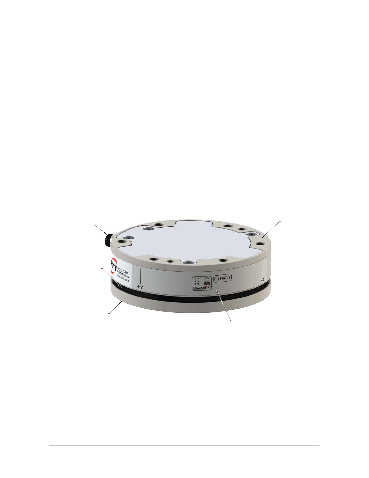
Figure 2.1—Axia80 F/T Sensor
Tool side
IP64 Seal
Mounting side
to robot or fixture
Tool side
for customer tooling
M8 male connector
for power and
communication and status LEDs
communication
Manual, F/T Sensor, Axia80
Document #9620-05-B-Axia80-02
Pinnacle Park • 1031 Goodworth Drive •Apex, NC 27539 • Tel:+1 919.772.0115 • Fax:+1 919.772.8259 • www.ati-ia.com
B-9
For more information on the electrical and software features of a specic communication interface version and the
applicable cable, refer to the ATI manual in the following table:
Table 2.1—ATI Communication/Software Manual Reference
Sensor Model
ATI P/N Communication
Type ATI Cable P/N Refer to the ATI Manual
9105-NET-
Axia80-MXX1,2 Ethernet 9105-C-ZC22-ZC283
9105-C-ZC28-U-RJ45S-x
ATI F/T Ethernet Axia manual
(ATI document #9620-05-C-Ethernet Axia)
9105-ECAT-
Axia80-MXX EtherCAT 9105-C-ZC22-ZC283
9105-C-ZC28-U-RJ45S-x
ATI F/T EtherCAT Axia manual
(ATI document #9620-05-C-EtherCAT Axia)
9105-RS422-
Axia80-MXX4RS422 9105-C-ZC27-ZC28-45,6 ATI F/T RS422 Axia manual
(ATI document #9620-05-C-RS422 Axia)
9105-RS485-
Axia80-MXX RS485 9105-C-ZC33-ZC34
9105-CP-ZC38-U-1.8,6
ATI F/T Serial Axia manual4,
Sections 4, 5, and 6
(ATI document #9610-05-Serial Axia)
Note:
1. MXX signies the full-scale torque measurement range; refer to Section2.1—ModelTypeIdentication.
2. This P/N was formally 9105-NET-AXIA80-MXX-ZC22.
3. Included in 9105-CKIT-ZC22-ZC28-X; refer to Table 3.2.
4. This model has an 8-pin M8 connector on the sensor. All other Axia80 models have a 6-pin M8 connector.
5. Included in 9105-CKIT-ZC27-ZC28-X; refer to Table 3.3.
6. Customers must use their own serial cable with a DB9 or USB connector to the ATI sensor cable.
Manual, F/T Sensor, Axia80
Document #9620-05-B-Axia80-02
Pinnacle Park • 1031 Goodworth Drive •Apex, NC 27539 • Tel:+1 919.772.0115 • Fax:+1 919.772.8259 • www.ati-ia.com
B-10
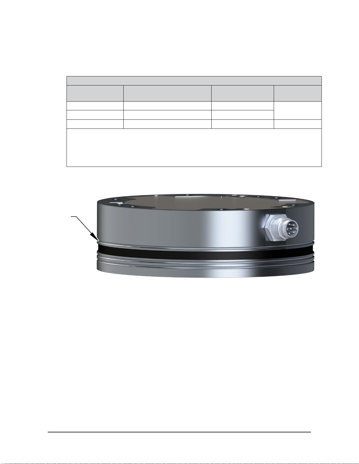
2.1 ModelTypeIdentication
The Axia80 sensor is available in three different model types (Axia80-MXX) that are identiable by the
number of grooves on the outer housing. The MXX sufx signies the full-scale torque measurement range.
For the calibration ranges of each model type, refer to Section 7.3—Calibration Ranges. An overview of
each model is summarized in the following table:
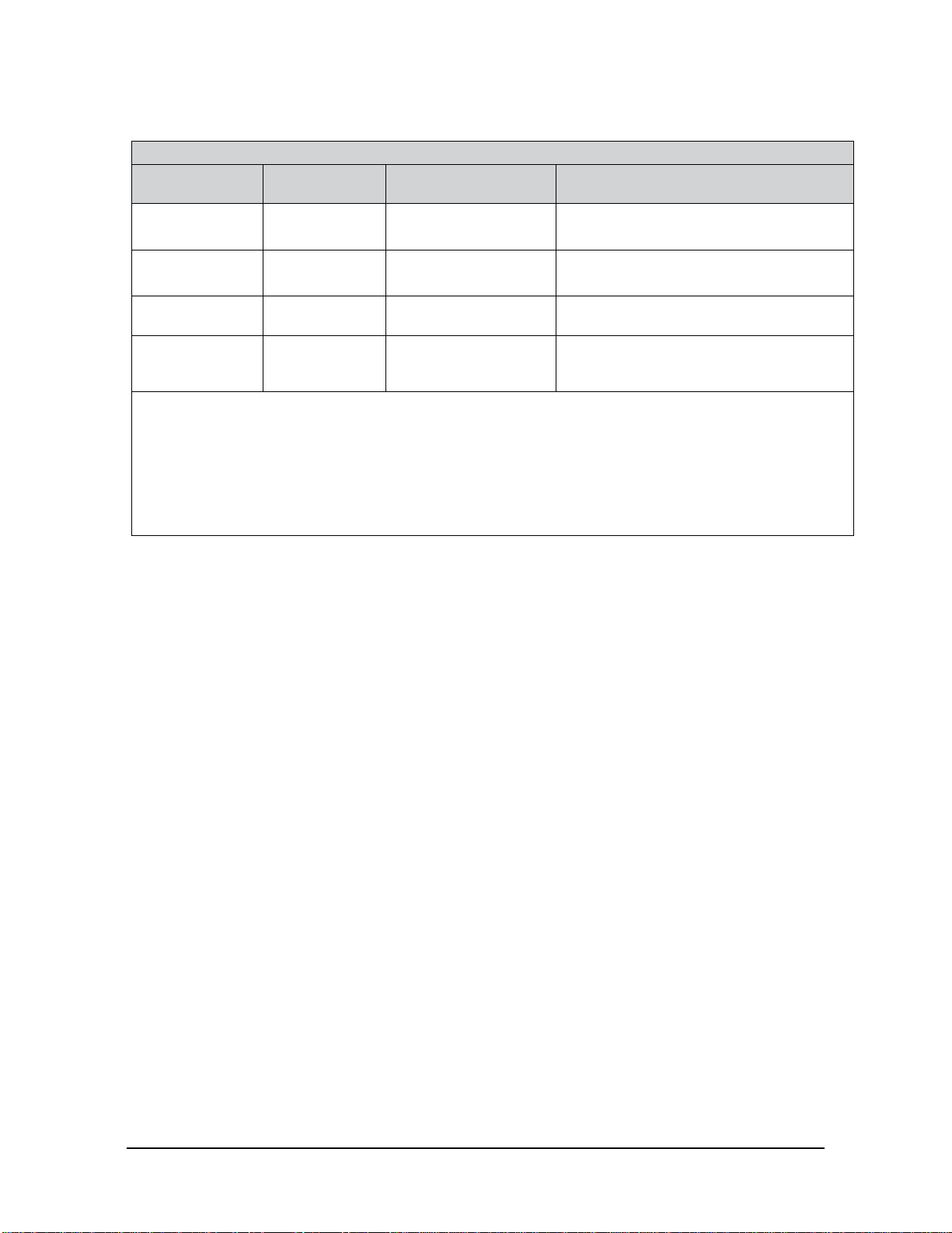
Table 2.2—Axia Models
Model Part Number Number of
Identifying Grooves1Material
Axia80-M8 9105-X3-Axia80-M8 3Aluminum
Axia80-M20 9105-X3-Axia80-M20 0
Axia80-M50 9105-X3-Axia80-M50 2 Stainless Steel
Notes:
1. Identifying grooves are physical indentations in the sensor body(refer to Figure 2.2). These grooves
provide users a quick visual method to dierentiate the sensor models.
2. For calibration ranges, refer to Section 7.3—Calibration Ranges.
3. The X signies the communication interface: NET, ECAT, RS422, or RS485.
Figure 2.2—Identifying Grooves (Axia80-M8 shown as a reference)
Identifying
Groove
Manual, F/T Sensor, Axia80
Document #9620-05-B-Axia80-02
Pinnacle Park • 1031 Goodworth Drive •Apex, NC 27539 • Tel:+1 919.772.0115 • Fax:+1 919.772.8259 • www.ati-ia.com
B-11
3. Installation
WARNING: Performing maintenance or repair on the sensor when circuits (for example:
power, water, and air) are energized could result in death or serious injury. Discharge and
verify all energized circuits are de-energized in accordance with the customer’s safety
practices and policies.
CAUTION: Using fasteners that exceed the customer interface depth penetrates the body of
the sensor, damages the electronics, and voids the warranty. For more information, refer to
the customer drawings.
CAUTION: Thread locker applied to fasteners must not be used more than once. Fasteners
might become loose and cause equipment damage. Always apply new thread locker when
reusing fasteners.
CAUTION: Avoid damage to the sensor from electrostatic discharge. Ensure proper
grounding procedures are followed when handling the sensor or cables connected to the
sensor. Failure to follow proper grounding procedures could damage the sensor.
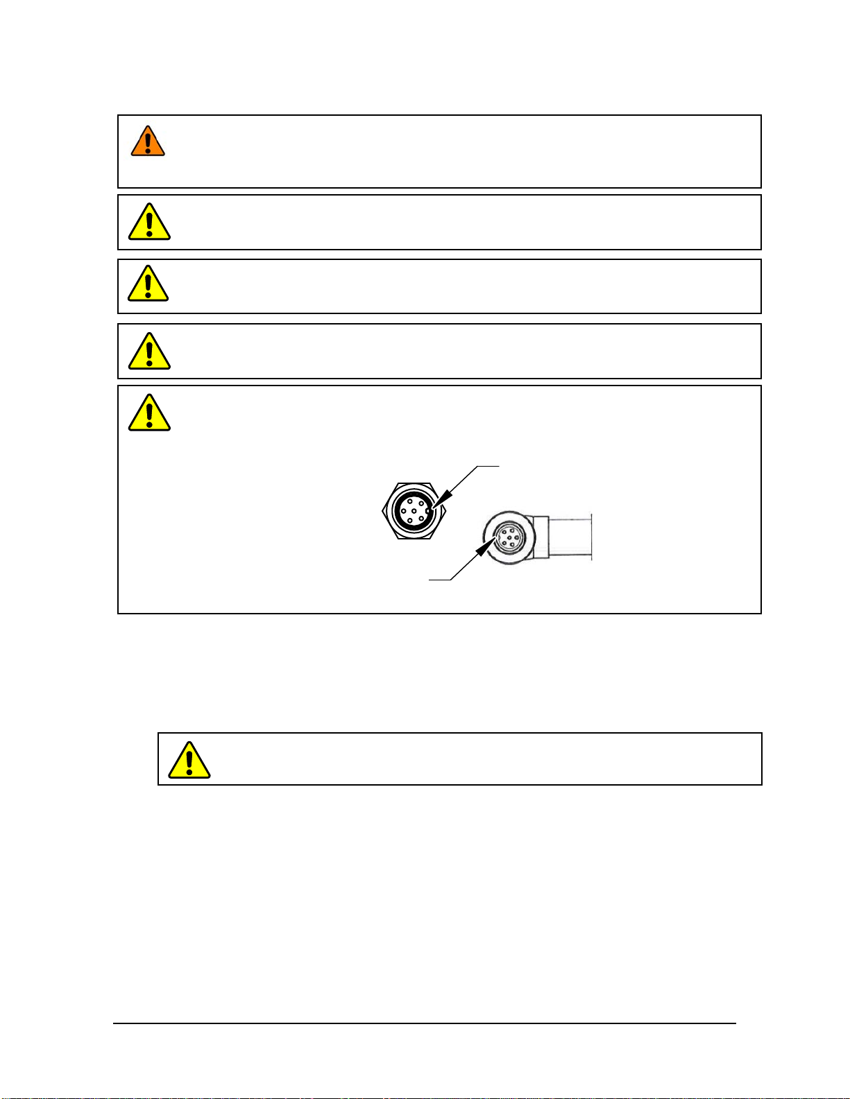
CAUTION: Do not apply excessive force to the sensor and cable connector during
installation, or damage will occur to the connectors. Align the keyway on the sensor and cable
connector during installation to avoid applying excessive force to the connectors.
Keyway on the
cable connector.
Keyway on the
sensor connector.
3.1 Interface Plates
The sensor’s mounting side attaches to a surface like the robot arm, and the sensor’s tool side attaches to the
customer tooling. ATI can supply robot mounting kits that include a mounting interface plate and fasteners;
for more information, contact ATI (refer to page B-2). If the customer chooses to supply their own interface
plates, refer to the following design guidelines and the ATI Axia sensor customer drawing.
CAUTION: Incorrect installation of interface plates can prevent the F/T sensor from
functioning properly.

Manual, F/T Sensor, Axia80
Document #9620-05-B-Axia80-02
Pinnacle Park • 1031 Goodworth Drive •Apex, NC 27539 • Tel:+1 919.772.0115 • Fax:+1 919.772.8259 • www.ati-ia.com
B-12
If the customer chooses to design and build an interface plate, consider the following points:
• The interface plate should include bolt holes for mounting fasteners as well as a dowel pin and boss for
accurate positioning to the robot.
• The thickness of the interface plate must provide sufcient thread engagement for the
mounting fasteners.
• The mounting fasteners should not interfere with the internal electronics of the sensor. For thread
depth, mounting patterns, and other details, refer to the ATI Axia sensor customer drawing.
• Do not use dowel pins that exceed length requirements and prevent interface plate from mating ush
with the robot. Fasteners that exceed length requirements create a gap between the interfacing surfaces
and cause damage.
• The interface plate must be as strong or stronger than the sensor so that maximum force and torque
values applied to the sensor do not distort the interface plate. For these force and torque values, refer to
Section 7—Specications.
• The interface plate must provide a at and parallel mounting surface for the sensor.
Figure 3.1 —Interface Plate(s)
Robot Arm
Locating Dowel
Mounting Fasteners
Locating Dowel
(6) M5 Mounting Fasteners
Mounting Interface Plate
Locating Boss
Locating Dowel Pin
(Customer Supplied)
Mounting Fasteners
(Customer Supplied)
3 mm Locating Dowel Pin
(Customer Supplied)
(6) M5 Mounting Fasteners
(Customer Supplied)
F/T Sensor
Locating Boss
Tool Interface Plate
(Customer Supplied)
.002 in (.05 mm)
.002 in (.05 mm)
.002 in (.05 mm)
.002 in (.05 mm)
A
4 mm Locating Dowel Pin
(Customer Supplied)
B
A
B
Manual, F/T Sensor, Axia80
Document #9620-05-B-Axia80-02
Pinnacle Park • 1031 Goodworth Drive •Apex, NC 27539 • Tel:+1 919.772.0115 • Fax:+1 919.772.8259 • www.ati-ia.com
B-13
3.2 Routing the Cable
The routing and bending radius of the cable depends upon the customer application. Unlike motionless
applications, where the cable is in a static condition, dynamic applications subject the cable to a repetitive
motion. For dynamic applications, restrain the cable at a distance that does not expose and damage the
sensor’s cable connection from the robot’s repetitive motion.
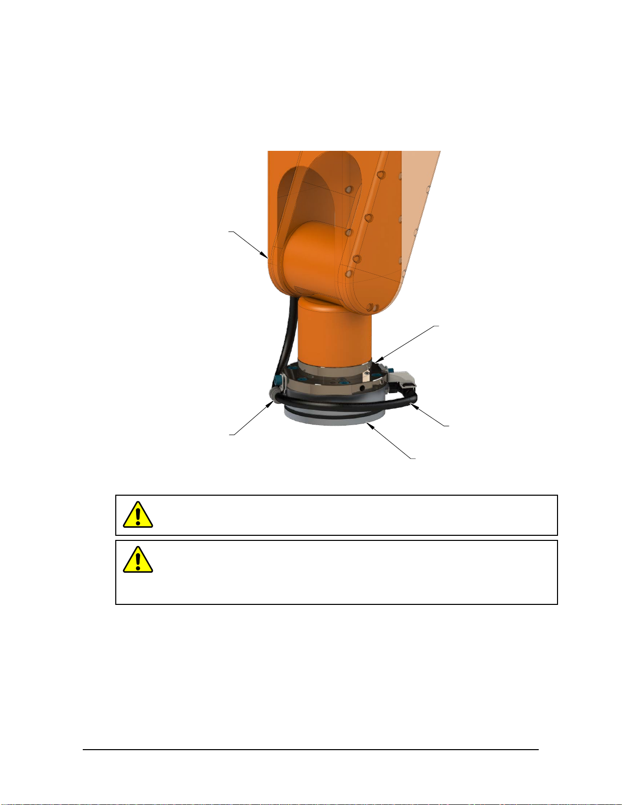
Figure 3.2—Routing of the Sensor Cable
Mounting
Interface Plate
Sensor Cable
F/T Sensor
Restrain cable to keep
repetitive motion from
affecting the cable
connection.
Robot Arm
CAUTION: Subjecting the connector to the repetitive motion will cause damage to the
connector. Restrain the cable close to the connector so that the repetitive motion of the
robot does not interfere with the cable connector.
CAUTION: Improper cable routing may cause injury to personnel, poor functionality
of critical electrical lines, or damage to the equipment. The electrical line, especially
where attached to the sensor’s connector, must be routed to avoid stress failure, sharp
bends, or a disconnection from the equipment. Damage to the sensor or cable from
improper routing will void the warranty.

Manual, F/T Sensor, Axia80
Document #9620-05-B-Axia80-02
Pinnacle Park • 1031 Goodworth Drive •Apex, NC 27539 • Tel:+1 919.772.0115 • Fax:+1 919.772.8259 • www.ati-ia.com
B-14
For added stability, zip ties can be used to secure the cable to a mounting bracket (refer to the following
gure). The zip ties should never contact the cable jacket.
Figure 3.3—Use Zip Ties on the Connector (sensor shown for reference only)
(2) Zip ties stabilize and secure
the connector. The zip tie does
not contact the cable.
Route the sensor cable so that it is not stressed, pulled, kinked, cut, or otherwise damaged throughout the
full range of motion. Use a robot dresspack solution, if possible. Examples of how to route the cable, if a
dresspack is not available, are shown in the following gures and descriptions. Afx the cable by using hook
and loop straps or Velcro®straps; do not use cable ties or zip ties.
Figure 3.4—Use Hook and Loop or Velcro®Straps on the Cable
(sensor shown for reference only)
Allow enough slack in
the cable to allow full range
of motion for the robot arm.
Use hook and loop or Velcro®straps to restrain
the cable around the robot arm.

Manual, F/T Sensor, Axia80
Document #9620-05-B-Axia80-02
Pinnacle Park • 1031 Goodworth Drive •Apex, NC 27539 • Tel:+1 919.772.0115 • Fax:+1 919.772.8259 • www.ati-ia.com
B-15
CAUTION: Do not use cable ties or zip ties to bundle cables or restrain the cable
to the robot arm. Directly axing cable ties or zip ties to the cable jacket will
damage the cable. Use hook and loop or Velcro straps on the cable jacket surfaces.
Examples of the incorrect and correct methods to restrain or bundle cables are in the
following pictures:
USE Velcro
®
straps to restrain
the cable around the robot arm.
DO NOT USE zip ties to restrain
the cable around the robot arm.
INCORRECT CORRECT
USE Velcro
®
straps
to bundle cables.
DO NOT USE zip ties
to bundle cables.
CAUTION: Do not damage or crush the cable by over tightening the
straps on the cable.
CAUTION: When routing the cables, do not bend less than the minimum bending
radius specied in Table 3.1. A bend radius too small causes the cable to fail from
fatigue of the robot’s repetitive motion.
Table 3.1—Sensor Cable Bending Radius and Dynamic Twist Angle
Cable Part Number Cable
Diameter
mm (in)
Static
Bending
Radius
(at room
temperature)
Dynamic
Bending
Radius
(at room
temperature)
Dynamic Cable Twist
Angle per Unit Length
mm in mm in
9105-C-ZC22-ZC28-X2,3 6 (0.24) 25 1 50 2
180°/m or 55°/ft
9105-C-ZC27-ZC28-X2,4 7 (0.28) 35 1.4 70 2.8
9105-C-ZC28-U-RJ45S-X26 (0.24) 25 1 50 2
9105-C-ZC33-ZC34-XXX 6.2 (.24) 31 1.3 62 2.5
Notes:
1. Temperature aects cable exibility. ATI recommends increasing the minimum dynamic bending radius for
lower temperatures.
2. The X in the part number represents the cable length. For more information, contact ATI.
3. Available in an ATI kit; refer to Table 3.2.
4. Available in an ATI kit; refer to Table 3.3.
5. For information specic to the cable part number, refer to the applicable manual in Table 2.1.
Manual, F/T Sensor, Axia80
Document #9620-05-B-Axia80-02
Pinnacle Park • 1031 Goodworth Drive •Apex, NC 27539 • Tel:+1 919.772.0115 • Fax:+1 919.772.8259 • www.ati-ia.com
B-16
3.3 Cable Kits
For images of the sensor support bracket and P-clip, refer to Figure 3.2 and Figure 3.5.
Table 3.2—Cable Kit 9105-CKIT-ZC22-ZC28-X
Part Number Description Quantity
9105-C-ZC22-ZC28-4 6-pin M8 connector to 8-pin M12 connector with a 4 m cable 1
9005-05-1078 (1) bracket, (1) M5 x 10 socket head cap screw, (1) M5 at
washer, and (1) tie 1
9005-05-1079 (1) P-clamp and (1) M5 x 10 socket head cap screw 1
Table 3.3—Cable Kit 9105-CKIT-ZC27-ZC28-X
Part Number Description Quantity
9105-C-ZC27-ZC28-4 8-pin M12 connector to 8-pin M12 connector with a 4 m cable 1
9005-05-1078 (1) bracket, (1) M5 x 10 socket head cap screw, (1) M5 at
washer, and (1) tie 1
9005-05-1079 (1) P-clamp and (1) M5 x 10 socket head cap screw 1
3.4 Install the Sensor
Parts required: Refer to Figure 3.5 and ATI Axia sensor customer drawing
Tools required: 4mmhexkeyor4mmlowprolehexkey(partofATIKitP/N9105-IP-2126)
Supplies required: Clean cloth, Loctite®242
1. Clean the mounting surfaces.
2. Use the mounting fasteners to attach the interface plate to the mounting surface.
NOTICE: When installing an interface plate:
• Screws must have a minimum thread engagement length of 4.5 mm. Maximum screw
thread engagement shall not exceed the threaded depth listed on the ATI Axia sensor
customer drawing.
• Unless otherwise specied, apply Loctite 242 to the (6) M5 socket head cap screws (class
12.9) so that the fasteners secure the sensor to the mounting plate.
3. Attach the mounting side of the sensor to the interface plate.
a. Using a 4 mm hex key, secure the sensor to the mounting interface plate with (6) M5 socket head
cap screws (class 12.9). Tighten the fasteners per the specications in the following table.
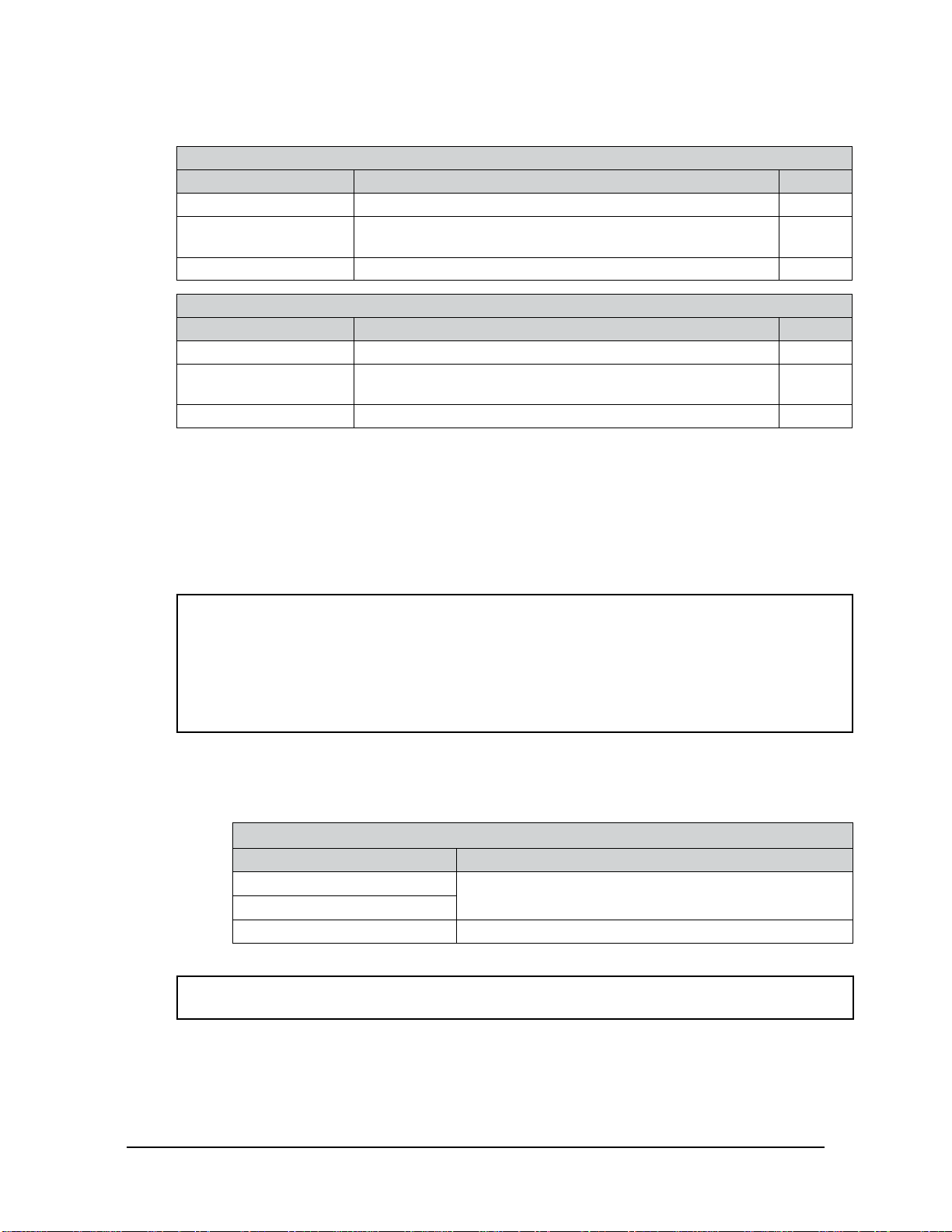
Table 3.4—Torque Values for Axia Models
Model Torque
Axia80-M8 52 in-lbs (5.88 Nm)
Axia80-M20
Axia80-M50 75 in-lbs (8.47 Nm)
4. Once the sensor is installed on the robot, the customer tooling can be installed.
NOTICE: The tool must not touch any other part of the sensor except the tool side; otherwise,
the sensor will not properly detect loads.
Other manuals for ATI Axia80
1
This manual suits for next models
3
Table of contents
Other Novanta Measuring Instrument manuals

Novanta
Novanta v40 User manual

Novanta
Novanta gem with smd24 User manual

Novanta
Novanta Synrad ti Series User manual

Novanta
Novanta SYNRAD Pulstar p100 User manual

Novanta
Novanta vi30 User manual

Novanta
Novanta i401 User manual

Novanta
Novanta JADAK FM-8 User manual

Novanta
Novanta 32-1 Laser User manual

Novanta
Novanta v30 User manual

Novanta
Novanta f201 User manual


