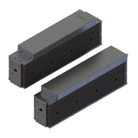
Novanta f201 User manual

ENGINEERED BY SYNRAD
f201 Laser
User Manual

TABLE OF CONTENTS PAGE |2
Table of Contents
Table of Contents ..............................................................................................................................................................................2
Important Information ......................................................................................................................................................................6
Trademark & Copywrite ....................................................................................................................................................................8
Warranty Information .......................................................................................................................................................................8
Sales, Application & Support .............................................................................................................................................................9
Sales & Application ............................................................................................................................................................................9
Customer Service...............................................................................................................................................................................9
Technical Support ..............................................................................................................................................................................9
Reference Materials ..........................................................................................................................................................................9
EU Headquarters .............................................................................................................................................................................10
Getting Started ................................................................................................................................................................................10
Introduction.....................................................................................................................................................................................11
f201 Nomenclature..........................................................................................................................................................................11
Unpacking........................................................................................................................................................................................12
Incoming inspection ........................................................................................................................................................................12
Packaging guidelines........................................................................................................................................................................12
Removing the lifting handles ...........................................................................................................................................................14
Inventory .........................................................................................................................................................................................15
Nomenclature (Continued)..............................................................................................................................................................16
Mounting .........................................................................................................................................................................................17
Connecting.......................................................................................................................................................................................19
Cooling connections ........................................................................................................................................................................19
Connecting.......................................................................................................................................................................................22
PS-96 power supply connections.....................................................................................................................................................24
PS-96 AC input section.....................................................................................................................................................................25
Control connections ........................................................................................................................................................................28
Other Connections...........................................................................................................................................................................29
Laser Safety......................................................................................................................................................................................31
Hazard Information .........................................................................................................................................................................32
Terms ...............................................................................................................................................................................................32
General Hazards ..............................................................................................................................................................................32
Other Hazards..................................................................................................................................................................................34
Disposal............................................................................................................................................................................................34
Thorium Safety ................................................................................................................................................................................34

TABLE OF CONTENTS PAGE |3
Additional Laser Safety Information................................................................................................................................................35
f201 label locations..........................................................................................................................................................................36
f201 label locations (continued) ......................................................................................................................................................37
f201 label locations (continued) ......................................................................................................................................................38
Compliance ......................................................................................................................................................................................39
Operation.........................................................................................................................................................................................46
Controls and indicators....................................................................................................................................................................47
f201 lasers........................................................................................................................................................................................47
Initial start-up ..................................................................................................................................................................................49
With a UC-2000 Controller ..............................................................................................................................................................49
Starting your f201 laser ...................................................................................................................................................................50
Without a UC-2000 Controller.........................................................................................................................................................50
Initial start-up ..................................................................................................................................................................................51
Technical Reference Summary ........................................................................................................................................................51
Technical overview ..........................................................................................................................................................................52
Laser tube ........................................................................................................................................................................................52
Optical resonator.............................................................................................................................................................................53
Internal RF power supply.................................................................................................................................................................54
Optical setup....................................................................................................................................................................................54
Controlling laser power ...................................................................................................................................................................56
Operating modes .............................................................................................................................................................................59
User I/O connections .......................................................................................................................................................................61
Input/output signals ........................................................................................................................................................................62
DC Power cables ..............................................................................................................................................................................72
Integrating F201 laser safety features.............................................................................................................................................73
OEM lasers.......................................................................................................................................................................................73
Remote interlock functions .............................................................................................................................................................74
Integrating f201 safety features ......................................................................................................................................................75
f201 general specifications ..............................................................................................................................................................77
Maintenance and troubleshooting..................................................................................................................................................79
Disabling f201 lasers ........................................................................................................................................................................79
Daily inspections..............................................................................................................................................................................79
Storage/shipping .............................................................................................................................................................................80
Cleaning optical components ..........................................................................................................................................................80
Cleaning guidelines..........................................................................................................................................................................81

TABLE OF CONTENTS PAGE |4
Cleaning optics.................................................................................................................................................................................82
Troubleshooting ..............................................................................................................................................................................83
Troubleshooting Introduction .........................................................................................................................................................83
Operational flow chart.....................................................................................................................................................................85
Functional block diagram ................................................................................................................................................................86
Status LEDs ......................................................................................................................................................................................87
Laser fault indications......................................................................................................................................................................90
Resetting faults................................................................................................................................................................................90
Troubleshooting ..............................................................................................................................................................................91
Other laser faults .............................................................................................................................................................................92
Beam delivery optics .......................................................................................................................................................................96
Index ..................................................................................................................................................................................................1
Table of Figures
Figure 2-1 Unpacking the laser......................................................................................................................................................................................13
Figure 2-2 Removing lifting handles. ............................................................................................................................................................................14
Figure 2-3 f201 shipping box contents. ........................................................................................................................................................................15
Table 2-1 f201 ship kit contents. ...................................................................................................................................................................................16
Figure 2-4 Fastening the f201 from below...................................................................................................................................................................18
Figure 2-5 Detail of fastening into mounting surface. ................................................................................................................................................18
Figure 2-6 Fastening f201 from below. ........................................................................................................................................................................19
Table 2- Dew point temperatures.................................................................................................................................................................................22
Figure 2-7 F201 cooling connections............................................................................................................................................................................23
Table 2-4 Three-phase AC electrical recommendations. ...........................................................................................................................................26
Figure 2-8 PS-96 interface..............................................................................................................................................................................................26
Table 2-5 Single-phase AC electrical recommendations............................................................................................................................................27
Table 2-6 Purge gas specifications. ...............................................................................................................................................................................30
Figure 3-1 100 hazard label locations...........................................................................................................................................................................36
Figure 3-2 F 200 hazard label locations........................................................................................................................................................................37
Figure 3-3 F 201 hazard label locations........................................................................................................................................................................38
Table 3-1 Class 4 safety features as required by CDRH and EN.................................................................................................................................42
Table 3-2 European Union Directives...........................................................................................................................................................................43
Figure 3-4 f201 Declaration Document........................................................................................................................................................................44

TABLE OF CONTENTS PAGE |5
Figure 3-5 (continued) F201 Declaration Document..................................................................................................................................................45
Figure 3-1 F201 controls and indicators (front)...........................................................................................................................................................47
Figure 3-2 F201 controls and indicators (rear). ...........................................................................................................................................................48
Figure 4-1 beam characteristics. ...................................................................................................................................................................................53
Figure 4-2 “Flying optics” beam path. ..........................................................................................................................................................................55
Table 4-1 Assist gas purity specifications. ....................................................................................................................................................................55
Figure 4-3 Typical F201 laser f201 waveforms. ...........................................................................................................................................................57
Figure 4-4 PWM Command signal waveform. ............................................................................................................................................................58
Table 4-2 PWM command signal specifications. ........................................................................................................................................................59
Table 4-3 User I/O pin descriptions. .............................................................................................................................................................................61
Table 4-3 User I/O pin descriptions (continued). ........................................................................................................................................................62
Figure 4-6 Auxiliary power supply wiring.....................................................................................................................................................................63
Table 4-4 Input circuit specifications. ...........................................................................................................................................................................65
Figure 4-8 Input equivalent schematic.........................................................................................................................................................................65
Figure 4-7 Quick Start Plug wiring diagram..................................................................................................................................................................66
Table 4-5 Output circuit specifications.........................................................................................................................................................................67
Figure 4-8 Customer-supplied interlock.......................................................................................................................................................................68
Figure 4-9 Customer-supplied interlock, negative voltage. .......................................................................................................................................68
Figure 4-10 PLC driven interlock signal.........................................................................................................................................................................69
Figure 4-11 Multiple PLC driven inputs. .......................................................................................................................................................................69
Figure 4-12 F201 laser output driving warning lamp..................................................................................................................................................70
Figure 4-13 F201 laser output driving relay. ................................................................................................................................................................70
Figure 4-14 F201 laser output driving PLC input module...........................................................................................................................................71
Table 4-7 f201 DC Power connector pinouts...............................................................................................................................................................72
Figure 4-15 F201 packaging diagram............................................................................................................................................................................76
Table 4-8 f201 general specifications. ..........................................................................................................................................................................77
Table 4-9 f201 general specifications (continued)......................................................................................................................................................78
Table 5-1 Required cleaning materials .........................................................................................................................................................................82
Figure 5-1 Operational flowchart..................................................................................................................................................................................85
Figure 5-2 f201 functional block diagram. ...................................................................................................................................................................86
Table 5-2 Status signals. .................................................................................................................................................................................................87
Table 5-3 Normal operating condition. ........................................................................................................................................................................88
Table 5-4 Quick Start Plug or interlock/shutter inputs not connected.....................................................................................................................88
Table 5-5 Interlock open condition...............................................................................................................................................................................88
Table 5-6 Over Temperature fault. ...............................................................................................................................................................................89
Table 5-7 Shutter closed condition. ..............................................................................................................................................................................89

PAGE |6
Table 5-8 VSWR fault......................................................................................................................................................................................................89
Table 5-9 Laser error codes. ..........................................................................................................................................................................................90
Important Information
For your protection, carefully read these instructions before installing and operating the scan
head.
Retain these instructions for future reference.
Novanta reserves the right to update this user manual at any time without prior notification.
If product ownership changes, this manual should accompany the product.
DANGER:Indicates a hazardous situation which, if not avoided, will result in serious injury or death.
Its use should be limited to the most extreme situations.
WARNING: Indicates a hazardous situation which, if not avoided, could result in serious injury or
death.
CAUTION: Indicates a hazardous situation which, if not avoided, could result in minor or
moderate injury.
Important: Indicates information considered important but not directly hazard related (e.g.,
security, hygiene, or equipment or property damage).
Safety Labels
DANGER:Laser radiation can cause severe retinal and corneal burns, burns on the skin, and may
pose a fire risk. To avoid injury and reduce risk of fire, please follow the control measures and
safety guidelines provided by the laser’s manufacturer, and those established by your Laser
Safety Officer (LSO), Radiation Safety Officer (RSO), or safety department of your business or
institution.
ESD Warning
MOVIA scan heads are electrostatic discharge-sensitive devices (ESD). The equipment should
remain sealed until the user is located at a proper static control station; improper handling could
cause damage to these electronics.
A proper static control station should include:
A soft grounded conductive tabletop or grounded conductive mat on the tabletop.
A grounded wrist strap with the appropriate (1 MΩ) series resistor connected to the tabletop mat
and ground.
An adequate earth ground connection, such as a water pipe or AC ground.
Conductive bags, trays, totes, racks, or other storage.
Properly grounded power tools.
Personnel handling ESD items should wear ESD protective garments and ground straps.

IMPORTANT INFORMATION PAGE |7
Important: Equipment returned to the factory must be shipped in anti-static packaging.
Important: Customers assume all responsibility for maintaining a laser-safe working environment.
Original equipment manufacturer (OEM) customers assume all responsibility for CDRH (Center
for Devices and Radiological Health) certification.
Customer Support
Before contacting Novanta for assistance, review appropriate sections in the manual that may answer
your questions.
After consulting this manual, please contact one of our worldwide offices between 9 AM and 5 PM
local time.
Americas, Asia Pacific
Novanta Headquarters, Bedford, USA
Phone: +1-781-266-5700
Email: photonics@novanta.com
Europe, Middle East, Africa
Novanta Europe GmbH, Wackersdorf, Germany
Phone: +49 9431 7984-0
Email: photonics@novanta.com
Milan, Italy
Phone: +39-039-793-710
Email: photonics@novanta.com
China
Novanta Sales & Service Office, Shenzhen, China
Phone: +86-755-8280-5395
Email: photonics.china@novanta.com
Novanta Sales & Service Office, Suzhou, China
Phone: +86-512-6283-7080
Email: photonics.china@novanta.com
Japan
Novanta Service & Sales Office, Tokyo, Japan
Phone: +81-3-5753-2460
Email: photonics.japa[email protected]

TRADEMARK & COPYWRITE PAGE |8
Trademark & Copywrite
NOVANTA® and f201 are registered trademarks of NOVANTA.
All other trademarks or registered trademarks are the property of their respective owners.
2018 by NOVANTA.
All rights reserved.
Warranty Information
This is to certify that F201 laser® f-Series lasers are guaranteed by NOVANTA to be free of all defects in
materials and workmanship for a period of one year from the date of shipment. This warranty does not
apply to any defect caused by negligence, misuse (including environmental factors), accident, alteration,
or improper maintenance. We request that you examine each shipment within 10 days of receipt and
inform NOVANTA of any shortage or damage. If no discrepancies are reported, NOVANTA shall assume
the shipment was delivered complete and defect-free.
If, within one year from the date of shipment, any part of the f-Series laser should fail to operate, contact
the NOVANTA Customer Service department at 1. 800.NOVANTA1 (outside the U.S. call 1.425.349.3500)
and report the problem. When calling for support, please be prepared to provide the date of purchase,
model number and serial number of the unit, and a brief description of the problem. When returning a unit
for service, a Return Authorization (RA) number is required; this number must be clearly marked on the
outside of the shipping container in order for the unit to be properly processed. If replacement parts are
sent to you, then you are required to send the failed parts back to NOVANTA for evaluation unless
otherwise instructed.
If your f-Series laser fails within the first 45 days after shipment, NOVANTA will pay all shipping charges
to and from NOVANTA when shipped as specified by NOVANTA Customer Service. After the first 45 days,
NOVANTA will continue to pay for the costs of shipping the repaired unit or replacement parts back to
the customer from NOVANTA. The customer, however, will be responsible for shipping charges incurred
when sending the failed unit or parts back to NOVANTA or a NOVANTA Authorized Distributor. In order
to maintain your product warranty and to ensure the safe and efficient operation of your f-Series laser,
only authorized NOVANTA replacement parts can be used. This warranty is void if any parts other than
those provided by NOVANTA are used.
NOVANTA and NOVANTA Authorized Distributors have the sole authority to make warranty statements
regarding NOVANTA products. NOVANTA and its Authorized Distributors neither assumes nor authorizes
any representative or other person to assume for us any other warranties in connection with the sale,
service, or shipment of our products. NOVANTA reserves the right to make changes and improvements in
the design of our products at any time without incurring any obligation to make equivalent changes in
products previously manufactured or shipped. Buyer agrees to hold NOVANTA harmless from any and all
damages, costs, and expenses relating to any claim arising from the design, manufacture, or use of the
product, or arising from a claim that such product furnished Buyer by NOVANTA, or the use thereof,
infringes upon any Patent, foreign or domestic.

SALES, APPLICATION & SUPPORT PAGE |9
Sales, Application & Support
Novanta Sales and Support
NOVANTA® worldwide headquarters are located north of Seattle in Mukilteo, Washington. U.S.A. Our
mailing address is:
NOVANTA 4600 Campus Place Mukilteo, WA 98275 U.S.A.
Phone us at:
1.800.NOVANTA1 (1.800.796.7231)
Outside the U.S.:
+1.425.349.3500
Fax:
+1.425.349.3667
E-mail:
Novanta@Novanta.com
Sales & Application
NOVANTA Regional Sales Managers work with customers to identify and develop the best CO2 laser
solution for a given application. Because they are familiar with you and your laser application, use them as
a first point of contact when questions arise. Regional Sales Managers also serve as the liaison between
you and our Applications Lab in processing material samples per your specifications. To speak to the
Regional Sales Manager in your area, call NOVANTA at 1.800. NOVANTA1.
Customer Service
For assistance with order or delivery status, service status, or to obtain a Return Authorization (RA)
number, contact NOVANTA at 1. 800.NOVANTA1 and ask to speak to a Customer Service representative,
or you can email us by sending a message to customercare@Novanta.com.
Technical Support
NOVANTA Regional Sales Managers are able to answer many technical questions regarding the
installation, use, troubleshooting, and maintenance of our products. In some cases, they may transfer your
call to a Laser, Marking Head, or Software Support Specialist. You may also e-mail questions to the
Technical Support Group by sending your message to Novantatechsupport@ Novanta.com.
Reference Materials

EU HEADQUARTERS PAGE |10
Your Regional Sales Manager can provide reference materials including Outline & Mounting drawings,
Operator’s Manuals, Technical Bulletins, and Application Newsletters. Most of these materials are also
available directly from the NOVANTA web site at http://www.Novanta.com.
EU Headquarters
For assistance in Europe, contact NOVANTA® European subsidiary, NOVANTA Europe, at:
©Novanta Distribution (USD) GmbH
Parkring 57-59
85748 Garching bei München,
Germany
Phone: +49 89 31707-0
web: www.Novanta.com
E-mail: EMEA-service@novanta.com
For assistance in China, contact NOVANTA® at:
Novanta China Sales and Service Center
2401-J, Bak Building, Hi-tech Park, Nanshan District Guangdong, PRC 518057
Phone: +86 (755) 8280 5395
Fax: +86 (755) 8672 1125
E-mail: sales-china@Novanta.com
web: www.Novanta.com
Getting Started
Use information in this section to prepare your f201 laser for operation. The order of information presented
in this section is the same as the order of tasks that you will need to perform. The best way to get your
laser ready for operation is to start at Unpacking and work your way through Connecting.
This section contains the following information:
•Introduction – introduces the f201 laser, lists important features, and describes F201 laser
nomenclature.
•Unpacking – provides important information about unpacking your f201 laser.
•Inventory – displays and describes all components shipped with your f201 laser.
•Mounting – describes how to attach your f201 laser to a mounting surface.
•Connecting – explains how to connect cooling tubing, power, and control cabling.

INTRODUCTION PAGE |11
Introduction
f201 lasers are part of a smaller-footprint lasers from NOVANTA featuring high power and excellent beam
quality. The circular beam provides more accurate cutting and faster processing speeds than competing
technologies. With an integrated RF power supply, meaning no external RF cables, the compact laser
housing mounts easily to flatbed cutters, robotic arms, or gantry systems making integration into your
production line simple and fast.
f201 features include:
•Compact resonator design
•Color-coded LEDs mirror user outputs
•Integrated RF power supply
•“Industrial-strength” ±5 V to 24 VDC I/O
•Built-in “tickle” generator
•Keyswitch and OEM models available.
f201 Nomenclature
f201 lasers are available only as OEM lasers; they do not include either a keyswitch or manual shutter
assembly. NOVANTA’s OEM lasers are primarily designed as components for integration into larger
processing systems by the Original Equipment Manufacturer (OEM) or System Integrator who bears the
responsibility for meeting the appropriate laser safety requirements for Class 4 laser systems.
Single tube
F201 laser f201 lasers contain a single tube (optical resonator) within the laser chassis. These lasers incor-
porate a single set of controls and indicators as well as a single set of cooling ports.
Model numbers
The last three characters in the F201 laser model number serve to designate the functional category,
cooling method, and model version. The functional category is indicated by an “S” (Switch-less) for OEM
models. The next letter indicates the cooling method: “W” for water-cooled units, “W” is omitted on f201
lasers since they are all water-cooled). The last letter in the model number indicates the current model
version beginning with “B”. For example, the model number. FSF201SC indicates a “C” version OEM water-
cooled f201 laser.
Important Note: All f201 lasers are water-cooled because of the integrated RF section’s heat
removal requirements. f201 lasers cannot be fan cooled. Damage to your laser will void your
warranty.
Caution: Possible Equipment Damage
Operating the laser at coolant temperatures above 22 °C (72 °F) may result in decreased
performance and/or premature failure of electronic components.

UNPACKING PAGE |12
Unpacking
The Unpacking section includes subsections:
•Incoming inspection
•Packaging guidelines
•Unpacking the laser
•Removing the lifting handles
Incoming inspection
Upon arrival, inspect all shipping containers for signs of damage. If you discover shipping damage,
document the damage (photographically if possible), then immediately notify the shipping carrier and
NOVANTA.
The shipping carrier is responsible for any damage occurring during transportation from NOVANTA to
your receiving dock.
Packaging guidelines
•To prevent equipment damage or loss of small components, use care when removing packaging
materials.
•After unpacking, review the Inventory section and verify that all components are on hand.
•Do not lift or support the laser using the cooling fittings; lift the laser by the mounting feet or
baseplate only.
•Save all shipping containers and packaging materials, including covers and plugs. Use these special-
ized packing materials when shipping the laser to another location.
•When packing a laser for shipment, be sure to remove all accessory items not originally attached
to the laser including beam delivery components, cooling tubing, etc.
•Refer to Packaging instructions drawings in the Technical Reference chapter for details on packag-
ing f201 lasers using NOVANTA-supplied shipping materials.
•When shipping water-cooled lasers, remember to drain all cooling water from the laser and then
cap the open fittings to prevent debris from entering the coolant path.
•F201 lasers and power supplies are heavy and awkward to move. Use appropriate lifting techniques,
additional personnel, and/or hoisting equipment to prevent a risk of injury when rigging this equip-
ment.
Warning: Serious Personal Injury
Lifting or moving f201 lasers poses a potential for injury. Use appropriate lifting techniques and/or
equipment to prevent a risk of injury. In some cases, you may require assistance from additional
personnel to safely unpack and move this equipment.

PACKAGING GUIDELINES PAGE |13
Unpacking the laser
To unbox the laser, refer to the figure below and perform the following steps:
Figure 2-1 Unpacking the laser.
1. Carefully cut the shipping strap wrapped around the container. This strap secures the upper lid to
the shipping crate.
2. Remove the upper lid and set it aside.
3. Remove the four polyurethane foam blocks that center the inner box within the outer crate.
4. Open the four flaps of the inner box.
5. Remove the three foam blocks cradling the top of the laser. To remove the center block, first slide
it forward several inches and then lift.
6. The laser is shipped with three lifting handles bolted to the mounting feet. Use these handle grips
to hoist or lift the laser from its shipping container. To prevent injury to personnel or damage to
the laser, always use a minimum of three people to handle the laser.
Important Note: All f201 lasers are water-cooled because of the integrated RF section’s heat
removal requirements. f201 lasers cannot be fan cooled. Damage to your laser will void your
warranty.
7. After removing the laser, pull out all the accessory items packaged with the laser

REMOVING THE LIFTING HANDLES PAGE |14
Removing the lifting handles
Once you have placed the laser in its final mounting location, refer to the figure below and perform the
following steps to remove the lifting attachments.
Figure 2-2 Removing lifting handles.
1. Locate the 8 mm hex wrench included with the accessory items.
2. Remove the M10 ×1.5 metric cap screws from the three locations shown in the above figure.
3. Retain the three M10 ×1.5 cap screws. Use these bolts for mounting if metric fasteners are required.
4. Store the lifting attachments so that they can be reinstalled if the laser is moved to another location.

INVENTORY PAGE |15
Inventory
F201 Lasers
Figure 2-3 f201 shipping box contents.

NOMENCLATURE (CONTINUED) PAGE |16
Nomenclature (Continued)
Table 2-1 f201 ship kit contents.
Shipping Box Contents Qty
DC Power Cable 1
Quick Start plug 1
BNC Control Cable (f201 only) 1
Cooling tubing 1
Mounting bolts 3/6
NOVANTA CO2 Welcome Flier 1
Spare 20 Ampere Fuses (not shown) 1/2
Chiller Fittings 2
Spherical Washer Sets (f201 only) 3
Cooling Kit 1
Final Test Report (not shown) 1
f201 contents description
Each item listed in the table above is described below:
DC Power Cable – carries DC power from the DC power supply to your F201 laser laser.
Quick Start Plug – connects to F201 laser’s User I/O connector. Jumpers are built into the plug to enable
F201 laser’s shutter and remote interlock circuits for initial start-up and testing.
BNC Control Cable (f201 only) – Coaxial cable carries the PWM Command signal from the UC-2000
Controller to the laser’s Quick Start Plug.
Cooling Tubing – Carries cooling water from the chiller to the laser and back. This black polyethylene
tubing is 1/2-inch O.D. by 30 feet and must be cut to length.
Mounting Bolts –Fasten our laser to your mounting surface. F201 laser f201 lasers include three metric (M8
×1.25 ×30 mm) and three standard (5/16–18 ×1.25" UNC) cap screws.
NOVANTA CO2 Welcome Flier – Contains an f201 customer welcome that provides where to find, opera-
tion, and maintenance information for your f201 single-tube laser on our website.
Spare 20 Ampere Fuses (not shown) – fast-blow fuses protect F201 laser’s internal circuitry.
Chiller Fittings – Adapt 1/2-inch O.D. tubing to 3/8" NPT threads for connection to a chiller. The chiller’s
inlet and outlet ports must be equipped with, or be adapted to, 3/8" NPT female threads.
Spherical Washer Sets (not shown) – used in conjunction with F201 laser f201 mounting bolts to align the
laser to your mounting surface. Shipped with f201 lasers only.
Cooling Kit – adapts the laser’s straight 1/2-inch coolant fittings to 90° adaptor fittings for either 1/2-inch
standard or 12-mm metric cooling tubing.
Final Test Report (not shown) – contains data collected during the laser’s final pre-shipment test.

MOUNTING PAGE |17
Mounting
f201 mounting
F201 mounting brackets are threaded to accept either metric or standard fasteners.
Important Note: As shown in the figure below, DO NOT use more than one fastener per
mounting location. Using two or more fasteners per mounting tab will cause damage to the laser;
use only one fastener per location to mount your f201 laser.
Fastening f201 lasers from above
To fasten your f201 laser to a mounting surface from above, perform the following steps:
1Refer to the appropriate outline and mounting drawing for dimensions and then drill and tap three
mounting holes into your mounting surface. For SAE installations, drill and tap three 5/16–18 (f201).
2Assemble three spherical washer sets as detailed in the Outline and Mounting drawing.
3Place the spherical washer sets over the threaded holes in your mounting surface.
4Carefully position the laser so that each thru hole in the baseplate aligns with a spherical washer
and threaded mounting hole.
5Insert the appropriate metric or standard cap screws, included in the laser’s ship kit, through the
baseplate, through the spherical washers, and into the threaded holes of the mounting surface (see
figure below). Turn the screws by hand until the threads engage.
6Evenly tighten all three cap screws. For M8 cap screws, torque to 12 N m; for M10 screws, torque
to 24 N m. When using 5/16" screws, torque to 13 ft lb.; for 3/8" cap screws, tighten to 23 ft lb.
Caution: Possible Equipment Damage
Do not use more than one fastener per mounting foot. Doing so will damage the laser.

MOUNTING PAGE |18
These hole locations (referenced by Note 2 on the O & M drawings) should correspond to the thru holes
labeled “A” as shown in the figure below.
Figure 2-4 Fastening the f201 from below.
Figure 2-5 Detail of fastening into mounting surface.
Fastening f201 lasers from below
To fasten your f201 laser to a mounting surface from below, perform the following steps:
1Refer to the appropriate outline and mounting drawing for dimensions and then drill three 8.5 mm
(f201) holes into your mounting surface. For SAE installations, drill three 0.332" (f201) holes into
your mounting surface.
2Assemble three spherical washer sets as detailed in the outline and mounting drawing.
3Place the spherical washer sets over the thru holes in your mounting surface.
4Carefully position the laser so that each threaded hole in the baseplate (labeled “M” or “S” in the
prior figure) aligns with a spherical washer and thru hole in the mounting surface.
5Insert the appropriate metric or standard cap screws, included in the laser’s ship kit, through the
mounting surface and spherical washers into the threaded holes of F201 laser’s baseplate (see
Figure 1-11). Turn the screws by hand until the threads engage.

CONNECTING PAGE |19
6Evenly tighten all three cap screws. For M8 cap screws, torque to 12 N m; for M10 cap screws,
tighten to 24 N m. When using 5/16" cap screws, torque to a value of 13 ft lb.; for 3/8" cap screws,
tighten to 23 ft lb.
These hole locations (referenced by Note 1 or Note 3 on the O & M drawings) should correspond to the
threaded holes labeled “M”, for metric, or “S”, for standard, as shown in the following figure.
Figure 2-6 Fastening f201 from below.
Connecting
The Connecting section includes subsections:
•Cooling connections
•PS-96 power supply connections
•Control connections
•Other connections
Cooling connections
Read Guidelines for cutting and installing tubing before installing any cooling tubing and then make sure
to connect the cooling system exactly as described for your particular laser.
Guidelines for cutting and installing tubing
•Cut tubing lengths generously to allow for trimming.
•Cut tubing squarely; diagonal cuts may not seal properly. Trim away burrs if the cut is “ragged”.
•Avoid excessive stress on fittings; create gentle bends when routing tubing close to connectors.
Excessive stress from sharp bends will compromise the sealing properties of the fitting.
•Never allow the tubing to kink since kinking severely restricts coolant flow.

COOLING CONNECTIONS PAGE |20
•Push tubing completely into the fitting, then pull the tubing to verify that it is locked into place.
Tubing extends into the fitting approximately 7/8 of an inch.
•If tubing must be disconnected from a fitting, first push and hold the tubing slightly into the fitting.
Next push the white fitting ring evenly towards the fitting, and then pull the tubing free.
•After disconnecting tubing from a fitting, trim 12.7 mm (1/2") from its end before reconnecting.
Trimming the end of the tubing before reconnecting the fitting provides an undisturbed sealing
surface.
Laser cooling fittings
If your integrated laser application uses metric cooling tubing, we recommend the installation of tubing
adaptors to convert the laser’s existing WATER IN/WATER OUT fittings from 1/2-inch standard to 12-
mm metric tubing. The ship kit sent with your f201 laser includes a cooling kit containing two each 1/2-
inch male to 1/2-inch female 90° adaptors and two each 1/2-inch male to 12-mm female 90° adaptors. If
required, many tubing and fitting manufacturers can supply 1/2-inch to 12-mm straight fittings.
Chiller preparation guidelines
•The ship kit includes chiller fittings with 3/8" NPT male threads. If these fittings will not connect to
your chiller, then you must provide fittings that will adapt the laser’s 1/2" O.D. polyethylene cooling
tubing to your chiller’s Inlet and Outlet ports.
•Because F201 laser’s cooling tubing is supplied in inch sizes, do not use metric tubing fittings unless
you have installed the appropriate inch-to-metric tubing adaptors. The use of metric fittings on
inch size tubing will lead to coolant leaks or may allow the pressurized tubing to blow off the fitting.
Coolants
NOVANTA recommends the laser’s cooling fluid contain at least 90% distilled water by volume. In closed-
loop systems, use a corrosion inhibitor/algaecide such as Optishield® Plus or equivalent as required. Avoid
glycol-based additives because they reduce the coolant’s heat capacity and high concentrations may
affect power stability. For NOVANTA lasers, the minimum coolant setpoint is 18 °C (64 °F) so glycol is not
necessary unless the chiller is subjected to freezing temperatures. If tap water is used, chloride levels
should not exceed a concentration of 25 parts per million (PPM) and total hardness should be below 100
PPM. Install a filter on the chiller’s return line and inspect frequently. f201 lasers use the following wetted
materials in the coolant path—aluminum, brass, copper, Delrin®, PBT, polyethylene, stainless steel, and
Viton®.
Caution: Possible Equipment Damage
f201 lasers incorporate special fittings that accept only standard 1/2" O.D. cooling tubing.
DO NOT REMOVE OR ADJUST THESE FITTINGS!
Each laser is shipped with a cooling kit that includes 90° push-on tubing connectors to adapt the
brass fittings to your choice of standard (1/2-inch) or metric (12-mm) cooling tubing.
Table of contents
Other Novanta Measuring Instrument manuals

Novanta
Novanta Synrad ti Series User manual
Novanta
Novanta SYNRAD Pulstar p100 User manual

Novanta
Novanta v30 User manual

Novanta
Novanta gem with smd24 User manual

Novanta
Novanta ATI Axia80 User manual

Novanta
Novanta p400 OEM Series User manual

Novanta
Novanta i401 User manual

Novanta
Novanta i401 User manual
Novanta
Novanta ventus with mpc6000 User manual

Novanta
Novanta JADAK FM-8 User manual

