Novanta p400 OEM Series User manual

ENGINEERED BY SYNRAD
p400 OEM Series
User Manual

IMPORTANT INFORMATION PAGE |2
Table of Contents
Important Information ......................................................................................................................................................................7
Trademark & Copywrite ....................................................................................................................................................................9
Warranty Information .......................................................................................................................................................................9
Sales, Application & Support ...........................................................................................................................................................10
Sales & Application ..........................................................................................................................................................................10
Customer Service.............................................................................................................................................................................10
Technical Support ............................................................................................................................................................................10
Reference Materials ........................................................................................................................................................................11
EU Headquarters .............................................................................................................................................................................11
Introduction.....................................................................................................................................................................................12
Guidelines & Content ......................................................................................................................................................................13
Unpacking/packing, Storage/shipping, Mounting, Connecting, Cooling.........................................................................................13
Contents and Description ................................................................................................................................................................13
Contents and Description (continued) ............................................................................................................................................14
Nomenclature..................................................................................................................................................................................15
Laser versions ..................................................................................................................................................................................15
Nomenclature (continued) ..............................................................................................................................................................16
Laser Safety Introduction ................................................................................................................................................................17
Hazard Information .........................................................................................................................................................................17
Terms ...............................................................................................................................................................................................18
General hazards...............................................................................................................................................................................19
Disposal............................................................................................................................................................................................20
Other hazards ..................................................................................................................................................................................20
Additional laser safety information .................................................................................................................................................21
p400 label locations.........................................................................................................................................................................22
Agency Compliance .........................................................................................................................................................................23
Center for Devices and Radiological Health (CDRH) requirements .................................................................................................23
European Union (EU) requirements RoHS compliance ...................................................................................................................25
Operation.........................................................................................................................................................................................29
Controls and indicators....................................................................................................................................................................29
Controls and indicators (continued)................................................................................................................................................30

IMPORTANT INFORMATION PAGE |3
Initial start-up ..................................................................................................................................................................................32
Technical reference .........................................................................................................................................................................32
Laser design .....................................................................................................................................................................................33
Optical setup....................................................................................................................................................................................36
RF power supply ..............................................................................................................................................................................37
Controlling laser power ...................................................................................................................................................................37
Control signals .................................................................................................................................................................................37
User I/O connections .......................................................................................................................................................................49
User I/O connection summary.........................................................................................................................................................50
Input/output signals ........................................................................................................................................................................52
Sample I/O circuits...........................................................................................................................................................................58
DC Power Cables..............................................................................................................................................................................62
DC voltage sense cable ....................................................................................................................................................................62
p400 web Interface..........................................................................................................................................................................62
Accessing the p400 web page..........................................................................................................................................................63
Event log page layout ......................................................................................................................................................................66
Changing the p400’s IP address.......................................................................................................................................................67
Alternate ethernet connection........................................................................................................................................................67
P400 Firmware upgrade procedure.................................................................................................................................................68
Integrating p400 Safety Features ....................................................................................................................................................74
Keyswitch functions.........................................................................................................................................................................75
Shutter functions .............................................................................................................................................................................75
Remote interlock functions .............................................................................................................................................................76
P400 Specifications..........................................................................................................................................................................77
P400 Flow Vs. Pressure curve ..........................................................................................................................................................79
P400 Outline and Mounting Drawings ............................................................................................................................................80
Maintenance & Troubleshooting.....................................................................................................................................................83
Maintenance....................................................................................................................................................................................83
Cleaning optical components ..........................................................................................................................................................86
Required cleaning materials ............................................................................................................................................................86
Cleaning optics.................................................................................................................................................................................87
Troubleshooting ..............................................................................................................................................................................88
Operational flowchart .....................................................................................................................................................................89
Status LED’s .....................................................................................................................................................................................90

IMPORTANT INFORMATION PAGE |4
DC Pre-Charge fault .........................................................................................................................................................................94
No-Strike fault..................................................................................................................................................................................94
Humidity fault..................................................................................................................................................................................94
Frequency Limit fault.......................................................................................................................................................................95
Duty Cycle/Pulse Width Limit fault..................................................................................................................................................95
Index ..................................................................................................................................................................................................1
Table of Figures
Figure 1-1 P400 shipping box contents. ..........................................................................................................................................14
Table 1-1 P400 ship kit contents......................................................................................................................................................15
Figure 1-2 Anatomy of a model number. ........................................................................................................................................16
Figure 2-1 P400 hazard label locations............................................................................................................................................22
Table 2-1 Class 4 safety features. ....................................................................................................................................................26
Table 2-2 European Union Directives. .............................................................................................................................................27
Figure 2-2 EU Compliance mark ......................................................................................................................................................28
Figure 3-1 p400 front panel controls and indicators. ......................................................................................................................30
Figure 3-2 p400 rear panel controls and indicators.........................................................................................................................31
Figure 4-1 Hybrid waveguide/unstable resonator design. ..............................................................................................................33
Figure 4-2 P400 beam ellipticity. .....................................................................................................................................................34
Figure 4-3 Converting 45° linear polarization to circular polarization.............................................................................................35
Table 4-1 Assist gas purity specifications. .......................................................................................................................................37
Figure 4-4 PWM command signal wave form (above) and Quasai Continuous Wave (QCW) explanation (below). ......................39
Figure 4-5 Typical power curve........................................................................................................................................................40
Figure 4-6 Representative output energy profile-5% duty cycle, 100Hz, time base 200 μs/Div.....................................................40
Figure 4-7 Representative output energy profile-5% duty cycle, 1kHz, time base 50 μs/Div. ........................................................41
Figure 4-8 Representative output energy profile-5% duty cycle, 10kHz, 50 μs/Div. timebase. ......................................................41
Figure 4-9 Representative output energy profile-10% duty cycle, 1kHz, 200 μs/Div. timebase. ....................................................42
Figure 4-10 Representative output energy profile-10% duty cycle, 10 kHz, 20.0 μs/Dev timebase. ..............................................42
Figure 4-11 Representative output energy profile-10% duty cycle, 50 kHz, 5.0 μs timebase.........................................................43
Figure 4-12 Representative output energy profile-20% duty cycle, 1 kHz, 100 μs/Dev timebase. .................................................44
Figure 4-13 Representative output energy profile-20% duty cycle, 5 kHz, 50 μs/Div. timebase. ...................................................44

IMPORTANT INFORMATION PAGE |5
Figure 4-14 Representative output energy profile-20% duty cycle, 50 kHz, 5.0 μs/Dev timebase. ................................................44
Figure 4-15 Representative output energy profile-20% duty cycle, 100 kHz, 5.0 μs timebase.......................................................45
Figure 4-16 Representative output energy profile-40% duty cycle, 1 kHz, 200 μs/Dev timebase. .................................................46
Figure 4-17 Representative output energy profile-40% duty cycle, 5 kHz, 50.0 μs/Dev timebase.................................................46
Figure 4-18 Representative output energy profile-40% duty cycle, 50 kHz, 5.0 μs/Dev timebase.................................................47
Figure 4-19 Representative output energy profile-40% duty cycle, 100 kHz, 5.0 μs/Dev timebase. ..............................................47
Figure 4-20 Representative output energy profile-50% duty cycle, 100 kHz, 5.0 μs/Dev timebase (approaching Quasi-
Continuous Wave [QCW] output)....................................................................................................................................................48
Figure 4-21 Representative output energy profile-45% duty cycle, 10 kHz, 5.0 μs/Dev timebase. ................................................48
Table 4-2 PWM Command signal specifications..............................................................................................................................49
Figure 4-22 User I/O connector pinouts. .........................................................................................................................................50
Table 4-3 User I/O pin descriptions. ................................................................................................................................................50
Figure 4-23 Auxiliary DC power diagram. ........................................................................................................................................52
Table 4-3 User I/O pin descriptions (Continued). ............................................................................................................................53
Table 4-3 User I/O pin descriptions (Continued). ............................................................................................................................53
Figure 4-24 Quick Start Plug wiring diagram. ..................................................................................................................................55
Table 4-3 User I/O pin descriptions (Continued). ............................................................................................................................55
Figure 4-25 Input equivalent schematic. .........................................................................................................................................55
Table 4-4 Input circuit specifications...............................................................................................................................................56
Figure 4-26 Output equivalent schematic. ......................................................................................................................................57
Table 4-5 Output circuit specifications. ...........................................................................................................................................58
Figure 4-27 Customer-supplied interlock. .......................................................................................................................................58
Figure 4-28 Customer-supplied interlock, negative voltage............................................................................................................58
Figure 4-29 PLC driven interlock signal............................................................................................................................................59
Figure 4-30 Multiple PLC driven inputs. ..........................................................................................................................................59
Figure 4-31 P400 output driving warning lamp. ..............................................................................................................................60
Figure 4-32 P400 output driving relay. ............................................................................................................................................60
Figure 4-33 P400 output driving PLC input module.........................................................................................................................61
Figure 4-34 P400 home page...........................................................................................................................................................64
Figure 4-35 P400 event log page. ....................................................................................................................................................66
Figure 4-36 P400 Change IP Address page. .....................................................................................................................................67
Figure 4-37 Windows Control Panel. ...............................................................................................................................................69
Figure 4-38 Programs and Features dialog......................................................................................................................................69
Figure 4-39 Windows Features dialog. ............................................................................................................................................70
Figure 4-40 Local Area Connection Properties dialog......................................................................................................................71
Figure 4-41 Internet Protocol (TCP/IP) Properties dialog. ...............................................................................................................72

IMPORTANT INFORMATION PAGE |6
Figure 4-42 Configure IP Address link on p400 home page.............................................................................................................73
Figure 4-43 p400 Change IP Address page. .....................................................................................................................................73
Figure 4-44 P400 web browser display............................................................................................................................................74
Table 4-6 P400 general specifications. ............................................................................................................................................77
Table 4-6 P400 general specifications continued. ...........................................................................................................................78
Figure 4-45 P400 pressure drop curve.............................................................................................................................................79
Figure 4-46 P400 outline & mounting dimensions. .........................................................................................................................81
Figure 4-47 P400 outline & mounting dimensions (mounting feet removed). ...............................................................................81
Figure 4-48 P400 packaging instructions.........................................................................................................................................82
Table 5-1 Required cleaning materials ............................................................................................................................................86
Figure 5-1 p400 operational flowchart. ...........................................................................................................................................89
Table 5-2 p400 Input/Output & LED Status Signals.........................................................................................................................90
Figure 5-2 Enable Java script in browser. ........................................................................................................................................96
Figure 5-3 Add IP address to list of authorized/trusted websites. ..................................................................................................97
Figure 5-3 Add IP address to list of authorized/trusted websites (Continued). ..............................................................................98

IMPORTANT INFORMATION PAGE |7
Important Information
For your protection, carefully read these instructions before installing and operating the scan
head.
Retain these instructions for future reference.
Novanta reserves the right to update this user manual at any time without prior notification.
If product ownership changes, this manual should accompany the product.
DANGER:Indicates a hazardous situation which, if not avoided, will result in serious injury or death.
Its use should be limited to the most extreme situations.
WARNING: Indicates a hazardous situation which, if not avoided, could result in serious injury or
death.
CAUTION: Indicates a hazardous situation which, if not avoided, could result in minor or
moderate injury.
Important: Indicates information considered important but not directly hazard related (e.g.,
security, hygiene, or equipment or property damage).
Safety Labels
DANGER:Laser radiation can cause severe retinal and corneal burns, burns on the skin, and may
pose a fire risk. To avoid injury and reduce risk of fire, please follow the control measures and
safety guidelines provided by the laser’s manufacturer, and those established by your Laser
Safety Officer (LSO), Radiation Safety Officer (RSO), or safety department of your business or
institution.
ESD Warning
MOVIA scan heads are electrostatic discharge-sensitive devices (ESD). The equipment should
remain sealed until the user is located at a proper static control station; improper handling could
cause damage to these electronics.
A proper static control station should include:
A soft grounded conductive tabletop or grounded conductive mat on the tabletop.
A grounded wrist strap with the appropriate (1 MΩ) series resistor connected to the tabletop mat
and ground.
An adequate earth ground connection, such as a water pipe or AC ground.
Conductive bags, trays, totes, racks, or other storage.
Properly grounded power tools.
Personnel handling ESD items should wear ESD protective garments and ground straps.
Important: Equipment returned to the factory must be shipped in anti-static packaging.
Important: Customers assume all responsibility for maintaining a laser-safe working environment.
Original equipment manufacturer (OEM) customers assume all responsibility for CDRH (Center
for Devices and Radiological Health) certification.

IMPORTANT INFORMATION PAGE |8
Customer Support
Before contacting Novanta for assistance, review appropriate sections in the manual that may
answer your questions.
After consulting this manual, please contact one of our worldwide offices between 9 AM and 5 PM
local time.
Americas, Asia Pacific
Novanta Headquarters, Bedford, USA
Phone: +1-781-266-5700
Email: photonics@novanta.com
Europe, Middle East, Africa
Novanta Europe GmbH, Wackersdorf, Germany
Phone: +49 9431 7984-0
Email: photonics@novanta.com
Milan, Italy
Phone: +39-039-793-710
Email: photonics@novanta.com
China
Novanta Sales & Service Office, Shenzhen, China
Phone: +86-755-8280-5395
Email: photonics.china@novanta.com
Novanta Sales & Service Office, Suzhou, China
Phone: +86-512-6283-7080
Email: photonics.china@novanta.com
Japan
Novanta Service & Sales Office, Tokyo, Japan
Phone: +81-3-5753-2460
Email: photonics.japa[email protected]

TRADEMARK & COPYWRITE PAGE |9
Trademark & Copywrite
NOVANTA© and p400 lasers are registered trademarks of NOVANTA.
All other trademarks or registered trademarks are the property of their respective owners.
2019 by NOVANTA.
All rights reserved.
Warranty Information
This is to certify that p400 lasers are guaranteed by NOVANTA to be free of all defects in materials and
workmanship for a period of one year from the date of purchase. This warranty does not apply to any
defect caused by negligence, misuse (including environmental factors), accident, alteration, or im-proper
maintenance. We request that you examine each shipment within 10 days of receipt and inform
NOVANTA of any shortage or damage. If no discrepancies are reported, NOVANTA shall assume the
shipment was delivered complete and defect-free.
If, within one year from the date of purchase, any part of the p400 laser should fail to operate, contact
the NOVANTA Customer Service department at 1.800.NOVANTA1 (outside the U.S. call 1.425.349.3500)
and report the problem. When calling for support, please be prepared to provide the date of purchase,
model number and serial number of the unit, and a brief description of the problem. When returning a
unit for service, a Return Authorization (RA) number is required; this number must be clearly marked on
the outside of the shipping container in order for the unit to be properly processed. If replacement parts
are sent to you, then you are required to send the failed parts back to NOVANTA for evaluation unless
otherwise instructed.
If your p400 laser fails within the first 45 days after purchase, NOVANTA will pay all shipping charges to
and from NOVANTA when shipped as specified by NOVANTA Customer Service. After the first 45 days,
NOVANTA will continue to pay for the costs of shipping the repaired unit or replacement parts back to
the customer from NOVANTA. The customer, however, will be responsible for shipping charges incurred
when sending the failed unit or parts back to NOVANTA or a NOVANTA Authorized Distributor. In order
to maintain your product warranty and to ensure the safe and efficient operation of your p400 laser,
only authorized NOVANTA replacement parts can be used. This warranty is void if any parts other than
those provided by NOVANTA are used.
NOVANTA and NOVANTA Authorized Distributors have the sole authority to make warranty statements
regarding NOVANTA products. NOVANTA and its Authorized Distributors neither assumes nor
authorizes any representative or other person to assume for us any other warranties in connection with
the sale, service, or shipment of our products. NOVANTA reserves the right to make changes and
improvements in the design of our products at any time without incurring any obligation to make
equivalent changes in products previously manufactured or shipped. Buyer agrees to hold NOVANTA
harmless from any and all damages, costs, and expenses relating to any claim arising from the design,
manufacture, or use of the product, or arising from a claim that such product furnished Buyer by
NOVANTA, or the use thereof, infringes upon any Patent, foreign or domestic.

SALES, APPLICATION & SUPPORT PAGE |10
Sales, Application & Support
Novanta Sales and Support
NOVANTA® worldwide headquarters are located north of Seattle in Mukilteo, Washington. U.S.A. Our
mailing address is:
NOVANTA 4600 Campus Place Mukilteo, WA 98275 U.S.A.
Phone us at:
1.800.NOVANTA1 (1.800.796.7231)
Outside the U.S.:
+1.425.349.3500
Fax:
+1.425.349.3667
E-mail:
Novanta@Novanta.com
Sales & Application
NOVANTA Regional Sales Managers work with customers to identify and develop the best CO2 laser
solution for a given application. Because they are familiar with you and your laser application, use them
as a first point of contact when questions arise. Regional Sales Managers also serve as the liaison
between you and our Applications Lab in processing material samples per your specifications. To speak
to the Regional Sales Manager in your area, call NOVANTA at 1.800. NOVANTA1.
Customer Service
For assistance with order or delivery status, service status, or to obtain a Return Authorization (RA)
number, contact NOVANTA at 1. 800.NOVANTA1 and ask to speak to a Customer Service representative,
or you can email us by sending a message to customercare@Novanta.com.
Technical Support
NOVANTA Regional Sales Managers are able to answer many technical questions regarding the
installation, use, troubleshooting, and maintenance of our products. In some cases, they may transfer
your call to a Laser, Marking Head, or Software Support Specialist. You may also e-mail questions to the
Technical Support Group by sending your message to Novantatechsupport@ Novanta.com.

REFERENCE MATERIALS PAGE |11
Reference Materials
Your Regional Sales Manager can provide reference materials including Outline & Mounting drawings,
Operator’s Manuals, Technical Bulletins, and Application Newsletters. Most of these materials are also
available directly from the NOVANTA web site at http://www.Novanta.com.
EU Headquarters
For assistance in Europe, contact NOVANTA® European subsidiary, NOVANTA Europe, at:
©Novanta Distribution (USD) GmbH
Parkring 57-59
85748 Garching bei München,
Germany
Phone: +49 89 31707-0
web: www.Novanta.com
E-mail: EMEA-service@novanta.com
For assistance in China, contact NOVANTA® at:
Novanta China Sales and Service Center
2401-J, Bak Building, Hi-tech Park, Nanshan District Guangdong, PRC 518057
Phone: +86 (755) 8280 5395
Fax: +86 (755) 8672 1125
E-mail: sales-china@Novanta.com
web: www.Novanta.com

INTRODUCTION PAGE |12
Introduction
Important Note: This Operation Manual explains operation activities related to p400 lasers. If you
cannot operate the unit using the information described in this manual, contact NOVANTA®
(+1.425.349.3500) or an authorized NOVANTA Distributor. Lift the laser only by the mounting feet or
baseplate. Do not lift or support the laser by its cooling fittings.
Please reference the Quick Start Guide for unpacking, mounting, and connecting. https://www.
Novanta.com/resources/libraries/manuals
Failure to properly package the laser using NOVANTA shipping box and foam/cardboard inserts as
shown in Packaging Instructions may void the warranty. Customers may incur additional repair charges
due to shipping damage caused by improper packaging.
Before beginning any maintenance or inspections of your p400 laser, be sure to completely disable the
laser by disconnecting the DC Power cable (or cables) from the rear of the laser.
If you operate your laser in dirty or dusty environments, contact NOVANTA about the risks of doing so
and precautions you can take to increase the longevity of your laser, marking head, and associated
optical components.
Caution: Possible Equipment Damage
Novanta does not recommend mounting lasers in a vertical, (head and/or tail down) position.
Contact the factory for limitations as a vertical orientation increases the risk of damage to the
laser’s optics.
If you operate your laser in dirty or dusty environments, contact NOVANTA about the risks of
doing so and precautions you can take to increase the longevity of your laser, marking head, and
associated optical components.
Warning: Serious Personal Injury
Remote interlock faults are not latched on OEM lasers. Clearing the fault condition re-enables the
RDY indicator and the laser will fire immediately provided the SHT indicator is lit and a PWM
Command signal is applied.
Because exposure to CO2 laser radiation in the (9-11) μm range can inflict severe corneal injuries
and seriously burn human tissue, the OEM or System Integrator must ensure that appropriate
safeguards are in place to prevent unintended lasing.
Warning: Serious Personal Injury
A risk of exposure to toxic elements may result when certain optical or beam delivery components
are damaged. In the event of damage to laser, marking head, or beam delivery optics, contact
NOVANTA, or the optics manufacturer for handling instructions.

PAGE |13
Guidelines & Content
Refer to the drawings, located in the technical reference section, when installing and operating your
p400 laser. Also reference the p400 quick start guide located on our website.
•Unpacking/Packing, Storage/Shipping, Mounting, Connecting, Cooling
•p400 nomenclature/features
Unpacking/packing, Storage/shipping, Mounting, Connecting, Cooling
NOVANTA® recommends saving all of the laser’s original packaging. This specially designed packaging
will protect the laser from damage during storage, relocation and/or shipping.
See the Quick Start Guide and the Drawings in the technical references section, for re-packaging p400
lasers for shipment and/or re-location. See the drawings located on our website Novanta.com, or in the
technical reference chapter in this operation manual mounting sections in the p400 Quick Start Guide
located on our website.
Contents and Description
Each item below is also listed in tables that follow:
p400 400 W Laser – The p400 laser is a compact, single tube 400 W laser producing near-perfect
beam quality with rise times < 50 μs and fall times < 100 μs and a PWM duty cycle range from 1% up to
50% (full power operation).
NOVANTA CO2 web flier – Shows the web links to the p400 manual &/or Quick Start Guide that
provides setup, operation, and maintenance information for your p400 laser.
Ethernet Crossover Cable – Provides the communications link between a host and the laser for
accessing operating parameters via a TCP/IP web-based interface.
BNC Control Cable – Coaxial cable carries the PWM Command signal from the UC-2000 Con-troller to
the laser’s Quick Start Plug.
12 mm Cooling Tubing – Carries cooling water from the chiller to the laser and back. This clear
polyethylene tubing is 12 mm O.D. by 30 feet and must be cut to length.
DC Power Cables – Carry DC power from the 48 V power supply to your p400 laser. Standard cable
length is 2.0 meters (6.5 feet) while optional 5.0 m (16 ft) power cables are available.
Quick Start Plug – Connects to User I/O connector. Jumpers are built into the plug to enable interlock
circuits for initial start-up and testing.
Mounting Hardware Kit (Not Standard) – Fasten to your mounting surface via the mounting feet use
four (4) each M10 ×1.5 mm capscrews and M10 washers for mounting the p400 laser. (*See footnotes
below).
Gas Purge Kit – Provides a filtering and connection point to the laser from your facility’s purge gas
system.
Spare Fuses (not shown) – 50 ampere fast-blow fuses protect your laser’s internal RF circuitry.
Final Test Report (not shown) – Contains data collected during the laser’s final pre-shipment test.
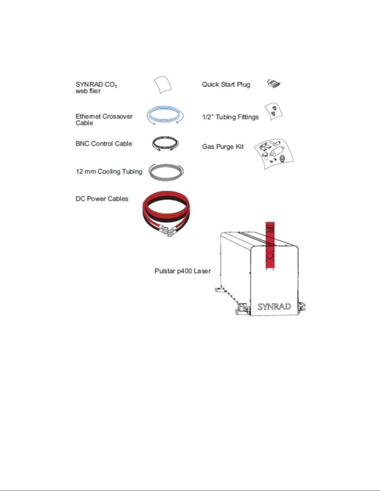
CONTENTS AND DESCRIPTION (CONTINUED) PAGE |14
Contents and Description (continued)
Figure 1-1 P400 shipping box contents.
1Maximum torque 11.3 Nm (100 in-lb.).
2Minimum thread engagement should be 20 mm or 0.787 in.
3Maximum thread engagement should be 25 mm or 0.984 in.
4Recommend using low-outgassing thread lock adhesive or locking washer.

NOMENCLATURE PAGE |15
Table 1-1 P400 ship kit contents.
Nomenclature
The nomenclature section includes:
•Model numbers
•Laser versions
The first three characters designate the Model Series, second three characters indicate the power option,
the next character signifies the safety option which is an “S” (Standard) for OEM models. The next
character indicates the model revision or laser build and the last three char-acters indicate the beam
options where 10.6 is 10.6um. Refer to the following figure for further examples.
Laser versions
P400 lasers are divided into two distinct functional categories: Keyswitch and OEM models. In addition
to a manual Keyswitch for resetting faults, all Keyswitch-equipped lasers incorporate a manual shutter
switch to block the laser’s output aperture as an added safety measure.
NOVANTA OEM lasers are primarily designed as components for integration into larger processing
systems by the Original Equipment Manufacturer (OEM) or System Integrator who bears the
responsibility for meeting the appropriate laser safety requirements for Class 4 laser systems.
p400 lasers are currently available only as OEM lasers; however, they do include an EM shutter assembly.

NOMENCLATURE (CONTINUED) PAGE |16
Nomenclature (continued)
Figure 1-2 Anatomy of a model number.

LASER SAFETY INTRODUCTION PAGE |17
Laser Safety Introduction
This section contains safety information that you will need to know prior to getting started. Read the
entire safety section. This will ensure you are familiar with the hazards and warnings prior to starting.
•Hazard Information – includes equipment label terms and hazards, please familiarize yourself
with all definitions and their significance.
•General & Other Hazards – provides important information about the hazards and unsafe
practices that could result in death, severe injury, or product damage.
•Disposal – information on your p400 laser parts and/or components as they pertain to disposal.
•Additional Safety Information – describes how to find additional information about your p400
laser.
•Compliance – explains in the subsections therein applicable and appropriate regulation
information.
Hazard Information
Hazard information includes terms, symbols, and instructions used in this manual or on the equipment to
alert both operating and service personnel to the recommended precautions in the care, use, and
handling of Class 4 laser equipment.
Warning: Serious Personal Injury
This Class 4 CO2 laser product emits invisible infrared laser radiation in the 9.3–10.6 μm wavelength
band.
Because direct or diffuse laser radiation can inflict severe corneal injuries, always wear eye protection
when in the same area as an exposed laser beam.
Do not allow the laser beam to contact a person!
This product emits an invisible laser beam that is capable of seriously burning human tissue.
Always be aware of the beam’s path and always use a beam block while testing.

TERMS PAGE |18
Terms
Certain terms are used throughout this manual or on the equipment labels. Please familiarize yourself
with their definitions and significance.
•Warning: Potential & Imminent hazards which, if not avoided, could result in death or serious
injury. Alerts operator of serious dangers, hazardous radiation, hazardous voltages, vapor hazard,
& reflective dangers.
•Danger: Hazards which, if not avoided, could result in minor or moderate injury. Alerts operator
of lifting dangers.
•Caution: Potential hazards or unsafe practices which, if not avoided, may result in product
damage. Alerts operator of equipment dangers.
•Important Note: Content specific information and/or recommendations.
Read the entire safety section. This will ensure you are familiar with the hazards and warnings prior
to starting.
A CO2 laser is an intense energy source and will ignite most materials under the proper conditions. Never
operate the laser in the presence of flammable or explosive materials, gases, liquids, or vapors.
Safe operation of the laser requires the use of an external beam block to safely block the beam from
traveling beyond the desired work area. Do not place your body or any combustible object in the path of
the laser beam. Use a water-cooled beam dump or power meter, or similar non-scattering,
noncombustible material as the beam block. Never use organic material or metals as the beam blocker;
organic materials, in general, are apt to combust or melt and metals act as specular reflectors which may
create a serious hazard outside the immediate work area.
Warning: Serious Personal Injury
For laser systems being used or sold within the U.S.A., customers should refer to and follow the laser
safety precautions described American National Standards Institute (ANSI) document Z136.1-2014,
Safe Use of Lasers.
For laser systems being used or sold outside the U.S.A., customers should refer to and follow the laser
safety precautions described in European Normative and International Electrotechnical Commission
documents IEC/ TR 60825-14:2014, Safety of Laser Products – §14: A User’s Guide.
Warning: Serious Personal Injury
The use of controls or adjustments or performance of procedures other than those specified herein
may result in hazardous radiation exposure.

GENERAL HAZARDS PAGE |19
General hazards
Following are descriptions of general hazards and unsafe practices that could result in death, severe
injury, or product damage. Specific warnings and cautions not appearing in this section are found
throughout the manual.
P400 lasers should be installed and operated in manufacturing or laboratory facilities by trained
personnel only. Due to the considerable risks and hazards associated with the installation and
operational use of any equipment incorporating a laser, the operator must follow product warning labels
and instructions to the user regarding laser safety. To prevent exposure to direct or scattered laser
radiation, follow all safety precautions specified throughout this manual and exercise safe operating
practices per ANSI Z136.1-2014, Safe Use of Lasers at all times when actively lasing.
Due to the specific properties of laser light, a unique set of safety hazards that differ from other light
sources must be considered. Just like light, lasers can be reflected, refracted, diffracted, or scattered.
Warning: Serious Personal Injury
Do not allow laser radiation to enter the eye by viewing direct or reflected laser energy.
CO2 laser radiation can be reflected from metallic objects even though the surface is darkened. Direct
or diffuse laser radiation can inflict severe corneal injuries leading to permanent eye damage or
blindness. All personnel must wear eye protection suitable for CO2 radiation, e.g., 9.3–10.6 μm when in
the same area as an exposed laser beam.
Eye wear protects against scattered energy but is not intended to protect against direct viewing of
the beam— never look directly into the laser output aperture or view scattered laser reflections from
metallic surfaces.
Enclose the beam path whenever possible. Exposure to direct or diffuse CO2 laser radiation can
seriously burn human or animal tissue, which may cause permanent damage.
This product is not intended for use in explosive, or potentially explosive, atmospheres!
Materials processing with a laser can generate air contaminants such as vapors, fumes, and/or
particles that may be noxious, toxic, or even fatal. Safety Data Sheets (SDS) for materials being
processed should be thoroughly evaluated and the adequacy of provisions for fume extraction,
filtering, and venting should be carefully considered. Review the following references for further
information on exposure criteria:
ANSI Z136.1-2014, Safe Use of Lasers, § 7.3.
U.S. Government’s Code of Federal Regulations: 29 CFR §1910, §§ Z.
Threshold Limit Values (TLV’s) published by the American Conference of Governmental Industrial
Hygienists (ACGIH).
It may be necessary to consult with local governmental agencies regarding restrictions on the venting
of processing vapors.
The use of aerosol dusters containing difluoroethane causes “blooming”, a condition that significantly
expands and scatters the laser beam. This beam expansion can affect mode quality and/or cause
laser energy to extend beyond the confines of optical elements in the system, possibly damaging
acrylic safety shielding. Do not use air dusters containing difluoroethane in any area adjacent to CO2
laser systems because difluoroethane persists for long time periods over wide areas.

DISPOSAL PAGE |20
Disposal
This product contains components that are considered hazardous industrial waste. If a situation occurs
where the laser is rendered non-functional and cannot be repaired, it may be returned to NOVANTA®
who, for a fee, will ensure adequate disassembly, recycling and/or disposal of the product.
Other hazards
The following hazards are typical for this product family when incorporated for intended use: (A) risk of
injury when lifting or moving the unit; (B) risk of exposure to hazardous laser energy through
unauthorized removal of access panels, doors, or protective barriers; (C) risk of exposure to hazardous
laser energy and injury due to failure of personnel to use proper eye protection and/or failure to adhere
to applicable laser safety procedures; (D) risk of exposure to hazardous or lethal voltages through
unauthorized removal of covers, doors, or access panels; (E) generation of hazardous air contaminants
that may be noxious, toxic, or even fatal.
Thorium Safety
•This laser system incorporates a II-VI Infrared optical component.
•This optical component contains a small amount of thorium fluoride, a type of source material (less
than 10% by weight).
•It is exempt from USNRC licensing regulations as an “unimportant quantity of source material” per
10 CFR 40.13(c) (7).
•Shaping, grinding, polishing, or alteration of the optical component is prohibited.
•Use of this optical component in contact lenses, spectacles, or in eyepieces in binoculars or other
similar optical instruments is prohibited.
Cleaning optical components is permitted so long as care is taken not to damage the coated surface of
the component as sold. This II-VI Infrared requirement only applies to lenses and optics manufactured and
distributed by II-VI Infrared. Distributing components or devices that contain lenses and optics
manufactured by other companies as if it were manufactured by II-VI Infrared is not in compliance with
USNRC distribution requirements.
U.S. distribution of components or devices that contain lenses and optics manufactured by other
companies which contain uranium and/or thorium requires a USNRC distribution license. Only II-VI Infrared
manufactured lenses and optics which contain thorium are covered by the II-VI Infrared distribution
license.
10 CFR 40.13(c) (7) Unimportant quantities of source material.
(7) Thorium or uranium contained in or on finished optical lenses and mirrors, provided that each lens or
mirror does not contain more than 10 percent by weight thorium or uranium or, for lenses manufactured
before August 27, 2013, 30 percent by weight of thorium; and that the exemption contained in this
paragraph does not authorize either:
Table of contents
Other Novanta Measuring Instrument manuals

Novanta
Novanta gem with smd24 User manual

Novanta
Novanta 32-1 Laser User manual

Novanta
Novanta ventus with mpc6000 User manual

Novanta
Novanta f201 User manual

Novanta
Novanta SYNRAD Pulstar p100 User manual

Novanta
Novanta JADAK FM-8 User manual

Novanta
Novanta vi30 User manual

Novanta
Novanta i401 User manual

Novanta
Novanta Synrad ti Series User manual

Novanta
Novanta v40 User manual


Popular Measuring Instrument manuals by other brands


SICK
SICK FLOWSIC100 Flare ADDENDUM TO OPERATING INSTRUCTIONS

Endress+Hauser
Endress+Hauser Cerabar S PMC71 Functional safety manual

Amphenol
Amphenol ENDEVCO Picomin 22 instruction manual

Wuntronic
Wuntronic COMMETER D3633 instruction manual

Biosan
Biosan DEN-1B User instructions

Sealey
Sealey Auto Service Series instructions


