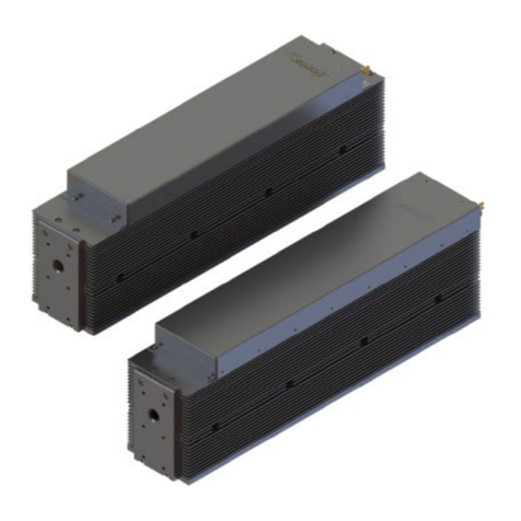
Novanta SYNRAD Pulstar p100 User manual

1 p100/150 Pulstar Water QSG version 3
Pulstar p100/150 Water Cooled Laser Quick Start Guide
100/150
a Novanta company
Important
Note:
See the Flyer 3D Marking Head and Pulstar p100/150 Laser Operators Manual for com-
plete installation details and instructions. A PDF version is available online at: http://www.
synrad.com/Manuals/manuals_laser.htm.
Unpacking:
Attention: For complete details, refer to the Flyer 3D WMP7 Quick Start Guide located on
our website. See the system inventory and mounting (sections) in your laser and
Flyer 3D Marking Head Operator’s Manuals.
Read all Danger, Warning, Caution terms, symbols, and instructions located in the (Laser Safety
Hazard information) sections in the Operation Manuals mentioned above.
3. Push the wire
harness through
the slot.
1
23
2. Locate the
wire harness in-
side the foam cap.
4
5. Correct way
to hold the laser.
4. Place the wire har-
ness on top of the
laser for lifting.
5
Caution: Carefully lift the foam caps, one of
them has the wire harness that will be
damaged if pulled.
Correct
Important
Note:
Caution! Unpacking the laser incorrectly can lead to damage that can void your
warranty. Keep All specially designed Foam and Packaging, you will need to re-use
it when moving your laser. Refer to this guide and the Technical Reference chapters in
the laser’s Operation Manual when re-packaging for shipping and/or relocation.
Mounting feet and/or rails are optional, for complete details, refer to the laser’s Operator’s Manual and
drawings on our website: www.synrad.com.
Caution! When re-packing the laser for relocation or shipment, use compressed shop air (less than
29 PSI) to blow out excess water from the cooling systems. Wear safety goggles! Nothing can be on
the sides of the laser at any time as damage will occur. The skin on the sides of the laser is fragile! All
box components must be stowed under the laser.
The wire harness &/or ports can be damaged in shipping if not re-packaged as shown above.

2 p100/150 Pulstar Water QSG version 3
100/150
Pulstar p100/150 Water Cooled Laser Quick Start Guide
a Novanta company
Readying your Laser for use:
Note: Remove the laser aperture self-adhesive lm before mounting your laser into nal posi-
tion.
1. Failure to remove the aperture seal can damage your system!
(Fan-Cooled ti60 Shown)
AVOID EXPOSURE
Invisible laser radiation
is emitted from
this aperture.
Failure
to remove
seal can
damage the
laser.
Mounting feet and/or rails are optional. See the laser’s Operator’s Manual and drawings on
our website: www.synrad.com.
Consult the factory for further mounting angle guidance outside >75% from the horizontal. When mounting
the laser to a baseplate, use only one metric or SAE fastener per mounting tab on the baseplate. Do not use
any type of jackscrew arrangement as this will twist the baseplate and may distort the tube.
Important
Note:
SYNRAD does not recommend mounting lasers in a vertical, (head and/or tail down)
position. Please contact the factory for limitations as a vertical orientation increases the risk
of damage to the lasers optics.

3 p100/150 Pulstar Water QSG version 3
Pulstar p100/150 Water Cooled Laser Quick Start Guide
100/150
a Novanta company
3. Locate the Mounting Hardware Kit ( ) Marking Head Safety tube, clamp, and Allen
screws, and the Laser mounting feet.
4. When attaching the Laser to the rail, make sure the notch is as shown in the gure above before going
on to the next step.
Remove the rail from the packaging. Assure
the notch is facing down and to the left. Very
important! Otherwise, re-work required
because the head will be mounted incorrectly.
Mounting the Laser to the Rail:
Attention: For further details, please refer to the Getting Started (System Inventory and Mount-
ing) Sections in the Pulstar p100/150 Laser and Flyer 3D Marking Head Operator’s
Manual.
Place the Laser and the Marking
Head on a suitable cart for re-location.
Notch
2
3
Cart
example
Place the Laser feet on the rail rst, then place the Laser ontop of the feet as shown. Ax the mounting feet
to the rail using the four Allen screws located in the mounting hardware kit.
1
Place the laser feet on top of the
rail rst, then place the laser ontop of
the feet as shown above.
Attach the Marking Head securely
to the rail with the four Allen screws.

4 p100/150 Pulstar Water QSG version 3
100/150
Pulstar p100/150 Water Cooled Laser Quick Start Guide
a Novanta company
Mounting the Marking Head to the Rail Continued:
5. Before mounting the Marking Head to the rail, assure the aperture seal is removed, slide the tube
onto the Marking Head rst, then put the clamp onto the tube as shown in the gure above (don’t
tighten the clamp’s Allen screws axing the tube to the laser until after the laser is mounted to
the rail).
AVOID EXPOSURE
Invisible laser radiation
is emitted from
this aperture.
8
9
6
5
4
INTERFACE
LASE
RDY
PWR
AB
7
SA Model Shown
1. Remove
the aperture seal.
3. Slide the
clamp onto
the tube.
Attention: Remove the laser aperture self-adhesive lm before mounting to the
rail. Don’t tighten the Allen screws on the clamp till the laser is mount-
ed to the rail.
2. Slide the tube
onto the Marking
Head.
4. Position the
Marking Head on the
rail as shown below.
Finger tighten the clamp to the Laser rst (see #5 above), then follow with an Allen Wrench as seen in the
gure above for all four Allen screws after the laser is rmly mounted to the rail with all four Allen screws.
5. Figer tighten the
clamp to the laser.
6. Follow up with
the Allen wrench.
Notch
1
23
4
5
6

5 p100/150 Pulstar Water QSG version 3
Pulstar p100/150 Water Cooled Laser Quick Start Guide
100/150
a Novanta company
6. Locate the Ship Kit ( ) Cooling ttings and 1/2 inch polyethylene tubing.
Attention: For further details, please see the specications in the Pulstar
p100/150 Operator’s Manual. Also see the Flyer 3D Operators Manual.
Cooling:
Important
Note:
Use distilled water as the coolant. If glycol is necessary, add no more than
10% by volume.
7. Set coolant temperature between 18–22 °C. If condensation occurs, increase coolant temperature a few
degrees at a time, up to a maximum of 28 °C.
Bottom port is for water out from Laser to chiller. See the top port for water in from the chiller.
Cooling
Connections
Water out to
the chiller
Water in from
the chiller

6 p100/150 Pulstar Water QSG version 3
100/150
Pulstar p100/150 Water Cooled Laser Quick Start Guide
a Novanta company
Water In
to chiller
Water Out
Water in to Laser from chiller.
Water out from Laser to chiller.
Flyer 3D i401 example.
Note: Assure the port for water out from Marking Head is connected to the water out from Laser
to chiller. Same is true for the water in from the chiller to the Marking Head/Laser.
8. Attach two quick connects the Marking Head cooling inlet/outlets. Assure the line out to chiller, from
the head is connected to the ‘Water Out’ port line on the Laser. Assure the line in from chiller, from the
head connects to the ‘Water In’ on the Laser.
Quick connecting to/from the Laser to the chiller.
Quick connecting to/from the Marking Head to the Laser.
Cooling (Connued):

7 p100/150 Pulstar Water QSG version 3
Pulstar p100/150 Water Cooled Laser Quick Start Guide
100/150
a Novanta company
Electrical:
Laser DC Power connection locations (note quick start plug is optional).
9. Connect the Laser VDC power cables to +,- connectors on the power supply.
10. Negative (black) DC power cable – tighten the M10 bolt fastening the black cable to the laser’s GND
terminal.
11. Positive (red) DC power cable – carefully tighten the M10 bolt fastening the red cable to the laser’s 48
VDC Power terminal.
Attention: For further details, please see the Getting Started (Connecting-DC pow-
er supply connections) section in the Pulstar p100/150 Laser Operator’s
Manual and Getting Started (Connecting-DC power cable) section in the
3D Marking Head Operator’s Manual.
1
Attach negative
DC power.
Attach positive
DC power.
2
Warning: Use the Quick Start Plug only for inial tesng or when troubleshoong. Remove
DC power before installing or removing the Quick Start Plug. Please refer to the
Geng Started (Connecng-laser connecons & the following Quick Start Plug)
secons in the Pulstar p150 Operator’s Manual.
Optional
Quick Start
Plug

8 p100/150 Pulstar Water QSG version 3
100/150
Pulstar p100/150 Water Cooled Laser Quick Start Guide
a Novanta company
Control Connecons:
The Quick Start Plug bypasses the laser’s safety interlock function
potentially exposing personnel to hazardous invisible infrared laser
radiation.
Warning:
Marking Head connections and nal control and electrical conguration.
12. Connect the Marking Head’s DC power, Ethernet (RJ-45) and BNC (Laser Control) communications
interface. (see the gure below). The ferrite bead, located at the end of the cable, should be connect-
ed to the FLyer 3D.
13. After assembly and mounting are complete, see the Mounting Head’s QSG for WinMark software setup.
If using a diode pointer and/or this is a new laser and you need to verify performance, see the Diode
Pointer Quick Start Guide located on our website.
BNC
Connector
RJ-45
Connector
Ferrite
Bead
DC
Power
(-) DC
power
(+) DC
power
Quick
Start Plug
Marking
Head
To DC
Power
Source
To PC
ethernet
port
To Laser
BNC port via
Quick Start
Plug
Other manuals for SYNRAD Pulstar p100
1
This manual suits for next models
1
Table of contents
Other Novanta Measuring Instrument manuals
Novanta
Novanta i401 User manual

Novanta
Novanta v30 User manual

Novanta
Novanta SYNRAD Pulstar p100 User manual

Novanta
Novanta gem with smd24 User manual

Novanta
Novanta ATI Axia80 User manual

Novanta
Novanta ventus with mpc6000 User manual

Novanta
Novanta 32-1 Laser User manual

Novanta
Novanta p400 OEM Series User manual

Novanta
Novanta f201 User manual

Novanta
Novanta JADAK FM-8 User manual