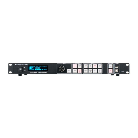
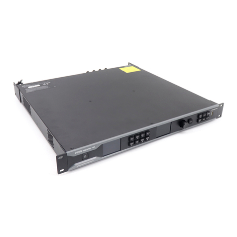
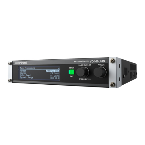
NovaStar HDR Master 4K User manual

HDR Master 4K
Video Processor
V1.0.0
User Manual
XI’AN NOVASTAR TECH CO., LTD.

HDR Master 4K Video Processor
User Manual
www.novastar.tech
i
Change History
Document Version
Release Date
Description
V1.0.0
2020-07-22
First release
XI’AN NOVASTAR TECH CO., LTD.

HDR Master 4K Video Processor
User Manual
www.novastar.tech
ii
Contents
1 Introduction.........................................................................................................................................................................................1
2 Appearance........................................................................................................................................................................................2
Front Panel..................................................................................................................................................................................2
Rear Panel...................................................................................................................................................................................3
3 Applications........................................................................................................................................................................................5
4 Home Screen.....................................................................................................................................................................................7
5 Menu Operations...............................................................................................................................................................................9
HDR..............................................................................................................................................................................................9
Input Settings............................................................................................................................................................................10
5.2.1 Input Source...................................................................................................................................................................10
5.2.2 Input Resolution.............................................................................................................................................................10
5.2.3 Color Space and Sampling Rate.................................................................................................................................11
5.2.4 Limited to Full.................................................................................................................................................................11
5.2.5 SDI Mosaic .....................................................................................................................................................................11
Output Settings.........................................................................................................................................................................12
5.3.1 Output Connector ..........................................................................................................................................................12
5.3.2 Output Resolution..........................................................................................................................................................12
5.3.3 Color Space and Sampling Rate.................................................................................................................................13
5.3.4 Bit Depth .........................................................................................................................................................................13
5.3.5 Sync Polarity...................................................................................................................................................................13
5.3.6 Output Color...................................................................................................................................................................13
5.3.7 SDI Mosaic .....................................................................................................................................................................14
Layer Settings...........................................................................................................................................................................14
5.4.1 Layer................................................................................................................................................................................15
5.4.2 BKG.................................................................................................................................................................................19
5.4.3 LOGO..............................................................................................................................................................................19
Display Control..........................................................................................................................................................................20
General Settings.......................................................................................................................................................................20
5.6.1 Synchronization .............................................................................................................................................................20
5.6.2 Multiviewer......................................................................................................................................................................20
5.6.3 Input Backup...................................................................................................................................................................21
5.6.4 FN Button........................................................................................................................................................................21
5.6.5 Miscellaneous.................................................................................................................................................................22
5.6.5.1 Return to Home.......................................................................................................................................................22
5.6.5.2 LCD Brightness .......................................................................................................................................................22
5.6.5.3 Output Timing ..........................................................................................................................................................22
5.6.5.4 Monitoring.................................................................................................................................................................23
5.6.5.5 Self-Test....................................................................................................................................................................23
5.6.5.6 USB Import...............................................................................................................................................................23
5.6.6 Factory Reset.................................................................................................................................................................24
5.6.7 Firmware Update ...........................................................................................................................................................24
5.6.8 About Us..........................................................................................................................................................................24
Communication Settings..........................................................................................................................................................24
Language...................................................................................................................................................................................25
6 Specifications...................................................................................................................................................................................26
XI’AN NOVASTAR TECH CO., LTD.

HDR Master 4K Video Processor
User Manual
www.novastar.tech
1
1 Introduction
The HDR Master 4K is a video processor converting SDR content into an HDR format. By analyzing the SDR
content and then intelligently filling in the missing information, the HDR Master 4K raises the dynamic range of
brightness, color gamut and color depth to HDR standard. With this all-round upgrade, the SDR video source
is converted into an HDR10 format that has a wider dynamic range of brightness, more colors and richer bright
and dark details.
The HDR Master 4K provides full 4K×2K@60Hz input and output connectors. Based on a pure hardware
system architecture, the HDR Master 4K allows for stable and highly-efficient processing capabilities, output
connector converting, SDI mosaic as well as long-distance optical fiber transmission.
Thanks to powerful capabilities of receiving a variety of video signals, ultra HD image processing and HDR10
image output, the HDR Master 4K can be widely used in applications such as high-end rental, stage control,
fine-pitch LED screens and video source conversion.
XI’AN NOVASTAR TECH CO., LTD.

HDR Master 4K Video Processor
User Manual
www.novastar.tech
2
2 Appearance
Front Panel
Area
Description
Power button
Press the button to power on the device.
Press the button and a prompt is displayed asking you whether you want to shut down
the device. Rotate the knob to select Shut Down and press the knob to power off the
device.
Monitoring
screen
Displays the monitoring information and input source RGB parade.
Input source and
number buttons
Press the buttons to switch the layer input source or to enter numbers.
Status LEDs for input source buttons:
−On (green): The input source is accessed and used by the layer.
−Flashing (red): The input source is not accessed but used by the layer.
−On (yellow): The input source is accessed but not used by the layer.
−Off: No input source is accessed or the input source is abnormal.
Status LEDs for number buttons:
−On (green): The number button is active and can be used to enter a number.
Control screen
Displays the device statuses, menus, submenus and messages.
Knob
Rotate the knob to select a menu item or adjust a parameter value.
Press the knob to confirm the selection or enter the submenu screen.
ESC button
Exit the current menu or cancel the operation.
Function buttons
FN1: A reserved button for a custom function, or used as a number button to enter 5
FN2: A reserved button for a custom function
HDR: Turn on or turn off the SDR to HDR converting function.
−On: SDR to HDR converting function turned on
−Off: SDR to HDR converting turned off
TEST: Enter the test pattern menu, or used as a number button to enter 5
−On: Test pattern opened
−Off: Test pattern closed
FRZ: Freeze the output image.
−On: Freeze function turned on
−Off: Freeze function turned off
SCALE: Make the layer size equal to the output resolution.
−On: Scaling function turned on (default)
−Off: Scaling function turned off
USB port
1x USB 2.0 (Type-A)
Insert a USB drive to update the device.
Insert a USB drive to import the BKG or LOGO files.
XI’AN NOVASTAR TECH CO., LTD.

HDR Master 4K Video Processor
User Manual
www.novastar.tech
3
Rear Panel
Input Card
R_4x12G SDI+1xHDMI2.0+1xDP1.2 Input Card
Connector
Qty
Standard
Description
HDMI 2.0
1
HDMI 2.0
Backward compatible
with HDMI 1.4 and
HDMI 1.3
Up to 4K×2K@60Hz input resolution
1080i/576i/480i deinterlacing
HDCP 2.2 and HDCP 1.4 compliant
HDR10 and HLG supported
Max. width: 8192 pixels, max. height: 4000 pixels
DP 1.2
1
DP 1.2
Backwards compatible
with DP 1.1
Up to 4K×2K@60Hz input resolution
1080i/576i/480i deinterlacing
HDCP 1.3 compliant
Max. width: 8192 pixels, max. height: 4000 pixels
12G-SDI
4
12G-SDI
Backward compatible
with 6G-SDI, 3G-SDI,
HD-SDI and SD-SDI
Supports ST-2082-1 (12G), ST-2081-1 (6G), ST-
424 (3G), ST-292 (HD) and SMPTE 259 (SD).
Up to 4K×2K@60Hz input resolution
1080i/576i/480i deinterlacing
For 3G-SDI, HD-SDI or SD-SDI inputs, SDI
mosaic input is supported.
Note:
When the input source is a 12G-SDI signal, you
must use CANARE / L-4.5CHD+ / UHDTV-SDI
SDI cables and the cable length should be less
than 50 m.
Output Card
R_1xHDMI2.0+4xFiber Output Card
Connector
Qty
Standard
Description
HDMI 2.0
1
HDMI 2.0
Backward compatible
with HDMI 1.4 and
HDMI 1.3
HDR10 supported
Up to 4K×2K@60Hz output resolution
Max. width: 8192 pixels, max. height: 4000 pixels
10G optical fiber
port
4
10G
OPT 1 and OPT 2 copy the output on HDMI 2.0.
OPT 3 copies the output on OPT 1.
OPT 4 copies the output on OPT 2.
R_4x12G SDI+1xHDMI2.0 Process Card
Connector
Qty
Standard
Description
XI’AN NOVASTAR TECH CO., LTD.

HDR Master 4K Video Processor
User Manual
www.novastar.tech
4
HDMI 2.0
1
HDMI 2.0
Backward compatible
with HDMI 1.4 and
HDMI 1.3
HDR10 supported
Up to 4K×2K@60Hz output resolution
Max. width: 8192 pixels, max. height: 4000 pixels
12G-SDI
4
12G-SDI
Backward compatible
with 6G-SDI, 3G-SDI,
HD-SDI and SD-SDI
Up to 4K×2K@60Hz output resolution on each
connector
For 3G-SDI, HD-SDI or SD-SDI outputs, SDI
mosaic output is supported.
R_Control Card
ETHERNET
Gigabit Ethernet port
Connect to the control PC.
USB
2x USB 2.0 (Type-A)
Insert a USB drive to update the firmware.
Insert a USB drive to import the BKG or LOGO files.
CONTROL UI
A reserved connector
GENLOCK
Connect to a synchronization signal.
Supports bi-level and tri-level.
IN: Accept the sync signal.
LOOP: Loop the sync signal.
Note:
The R_1xHDMI2.0+4xFiber output card and R_ 4x12G SDI+1xHDMI2.0 process card output the same
content synchronously.
Always place the device near the electrical outlet during use.
XI’AN NOVASTAR TECH CO., LTD.

HDR Master 4K Video Processor
User Manual
www.novastar.tech
5
3 Applications
The HDR Master 4K supports the following three connection methods.
When a sending device is required, the sending device must be NovaStar’s independent controller or all-in-
one controller, such as NovaPro UHD, NovaPro UHD Jr and MCTRL 4K. When SDR to HDR converting
function is enabled on the HDR Master 4K, the HDR function on the sending device must be turned on at the
same time.
HDMI connection for short-distance transmission
Connect the HDMI output connector of the device to the sending device using an HDMI cable, and then
connect the sending device to the LED screen using Ethernet cables.
OPT connection for long-distance transmission
Connect the OPT ports of the device to the fiber converters using optical fiber cables, and then connect the
fiber converters to the LED screen using Ethernet cables.
SDI connection
One of the four SDI connectors is used for output, and the other three SDI connectors output the same
content synchronously. When the output is a 3G-SDI signal, SDI mosaic output is supported.
XI’AN NOVASTAR TECH CO., LTD.

HDR Master 4K Video Processor
User Manual
www.novastar.tech
6
Connect the SDI output connectors to the sending device using SDI cables, and then connect the sending
device to the LED screen using Ethernet cables.
Note:
When SDR to HDR converting function is enabled, the HDMI output connector cannot be connected to a
monitor directly because the monitor does not support the playback of HDR content.
Cable Clip and Cable Tie Installation
The device is provided with a cable clip and a cable tie. Please follow the subsequent procedure to install the
cable clip and cable tie.
Step 1 Unfasten the screw on the device ear next to the power connector.
Step 2 Place the cable tie onto the ear and fix the tie with the screw.
Step 3 Insert the cable tie into the fixing hole on the cable clip, and adjust the clip slightly for better usage.
Figure 3-1 Cable clip and cable tie installation
XI’AN NOVASTAR TECH CO., LTD.

HDR Master 4K Video Processor
User Manual
www.novastar.tech
7
4 Home Screen
Figure 4-1 Home screen
Area
Description
HDR Master 4K
Displays the device name.
192.168.0.10
Displays the device IP address.
Layer
: Displays the layer input source.
: Indicates whether the current input source is an HDR source. If it is, HDR
is displayed; if not, HDR is not displayed.
1920×1080@60: Displays the resolution of the current input source.
Output
Displays the current output resolution.
OPT
Indicates the OPT port working mode.
OPT 3 copies the output data on OPT 1.
OPT 4 copies the output data on OPT 2.
Highlighted: The OPT port is connected.
Gray: The OPT port is not connected.
GEN
: The Genlock function is turned on and successfully used.
: The Genlock function is turned off.
SDR→HDR
: SDR to HDR converting function is turned on.
: SDR to HDR converting function is turned off.
USB
: A USB drive is inserted and has been detected by the device.
: No USB drive is detected.
Connection
: The device is connected to the control PC.
XI’AN NOVASTAR TECH CO., LTD.

HDR Master 4K Video Processor
User Manual
www.novastar.tech
8
Area
Description
: The device is not connected to the control PC.
XI’AN NOVASTAR TECH CO., LTD.

HDR Master 4K Video Processor
User Manual
www.novastar.tech
9
5 Menu Operations
Button descriptions:
Knob:
On the home screen, press the knob to enter the main menu screen.
On the main menu screen, rotate the knob to select a menu item, and press the knob to confirm the
selection or enter the submenu.
When a menu item with parameters is selected, rotate the knob to adjust the parameters. Please note
that after adjustment, you need to press the knob again to confirm the adjustment.
ESC: Press the button to exit the current menu or cancel the operation.
Hold down the knob and ESC button simultaneously for 3s or longer to lock or unlock the device front panel
buttons.
HDR
On the home screen, press the knob to enter the main menu screen. Rotate the knob to select HDR and press
the knob to enter the HDR settings screen.
Figure 5-1 HDR
SDR→HDR: Turn on or turn off SDR to HDR converting function.
−On: Turn on the converting function.
−Off: Turn off the converting function.
Compare: Turn on or turn off the comparing function between the two output images.
−On: Show the contrast between the SDR and HDR images.
−Off: Do not show the contrast.
Source: Select the input source for the comparing. The connected input sources or the built-in demo can
be used as the source.
Dividing line: The line moving on the image
XI’AN NOVASTAR TECH CO., LTD.

HDR Master 4K Video Processor
User Manual
www.novastar.tech
10
The HDR content is on the left and the SDR content is on the right.
−Move: The dividing line moves from the left to right.
−Pause: The dividing line stops moving.
Line Speed: Set the moving speed of the dividing line. The value range is 1 to 5. 1 stands for the slowest
speed and 5 stands for the fastest speed.
Input Settings
5.2.1 Input Source
The HDR Master 4K provides a variety of input connectors, including DP 1.2, HDMI 2.0, SDI-1, SDI-2, SDI-3
and SDI-4.
On the main menu screen, go to Input Settings > Source to show the input source list. Rotate the knob to
select the target input source and press the knob to confirm the selection.
Figure 5-2 Selecting input source
5.2.2 Input Resolution
You can set the input resolution by either of the following ways.
Standard resolution
Custom resolution
Figure 5-3 Setting input resolution
Note:
The SDI connector does not support input resolution settings.
Standard Resolution
On the input resolution screen, rotate the knob to select Standard Resolution. After you have selected the
desired resolution and frame rate, rotate the knob to select Apply and press the knob to apply the settings. If
Apply is not selected, the settings will not take effect.
XI’AN NOVASTAR TECH CO., LTD.

HDR Master 4K Video Processor
User Manual
www.novastar.tech
11
Figure 5-4 Standard resolution
Custom Resolution
On the input resolution screen, rotate the knob to select Custom Resolution. After you have set the desired
width, height and frame rate, rotate the knob to select Apply and press the knob to apply the settings.
Figure 5-5 Custom resolution
5.2.3 Color Space and Sampling Rate
View the color space and sampling rate of the current input source, which are read automatically by the device
and cannot be set.
5.2.4 Limited to Full
RGB full means the ability to show 0-255 which is the full color range, but RGB limited can only show a limited
color range.
When the color range for the input source is RGB limited, turn on this function. The device will automatically
perform the conversion calculation and convert the color range of the input source to RGB full.
5.2.5 SDI Mosaic
Step 1 Go to Input Settings > SDI Mosaic to enter the SDI mosaic screen.
Step 2 Turn on the SDI mosaic function.
Figure 5-6 SDI mosaic
Step 3 Rotate the knob to select Layout and press the knob to show the available layouts.
Four SDI mosaic layouts are provided as follows.
: Two vertical mosaic areas
: Four vertical mosaic areas
XI’AN NOVASTAR TECH CO., LTD.

HDR Master 4K Video Processor
User Manual
www.novastar.tech
12
: Two horizontal mosaic areas
: Two vertical and two horizontal mosaic areas
Step 4 Rotate the knob to select the desired layout and press the knob to apply the layout.
Note:
SDI mosaic function is available when the input signal is in 3G-SDI, HD-SDI or SD-SDI format.
All the SDI sources used in the SDI mosaic must be of the same resolution and frame rate.
Output Settings
5.3.1 Output Connector
On the main menu screen, go to Output Settings > Connector to show the output connector list. Rotate the
knob to select the target output connector and press the knob to confirm the selection.
5.3.2 Output Resolution
You can set the output resolution by either of the following ways.
Standard resolution
Custom resolution
Standard Resolution
On the output resolution screen, rotate the knob to select Standard Resolution. After you have selected the
desired resolution and frame rate, rotate the knob to select Apply and press the knob to apply the settings. If
Apply is not selected, the settings will not take effect.
Figure 5-7 Standard resolution
Custom Resolution
On the output resolution screen, rotate the knob to select Custom Resolution. After you have set the desired
width, height and frame rate, rotate the knob to select Apply and press the knob to apply the settings.
XI’AN NOVASTAR TECH CO., LTD.

HDR Master 4K Video Processor
User Manual
www.novastar.tech
13
Figure 5-8 Custom resolution
5.3.3 Color Space and Sampling Rate
Set the color space and sampling rate for the current output connector, to enable the connected device to
receive and process the signal.
The HDR Master 4K supports the following three color spaces and sampling rates.
RGB/4:4:4
YCbCr/4:4:4
YCbCr/4:2:2
5.3.4 Bit Depth
Bit depth is the number of bits used by each pixel in the computer and refers to the color information stored in
an image. The higher the bit depth of the input image, the more colors it can store. The HDR Master 4K
supports 8, 10 and 12-bit depth output. It defaults to 10-bit.
5.3.5 Sync Polarity
Set the sync polarity of the output image according to the requirements of the backend device so that it can be
compatible with the backend device.
5.3.6 Output Color
Rotate the knob to select Output Color and press the knob to enter the Output Color screen. Then press the
knob again and rotate it to edit the values of the color parameters. For detailed parameter settings, see Table
5-1.
Figure 5-9 Output color
Table 5-1 Output color
Parameter
Range
Default
Description
Brightness
0 to 100
50
Adjust the brightness of the output image. The greater the
value, the brighter the image.
Contrast
0 to 100
50
Adjust the brightness difference between the white and
black of the output image. The greater the value, the bigger
the difference.
Saturation
0 to 100
50
Adjust the colorfulness of the output image. The greater the
value, the more colorful the image.
Hue
–180 to +180
0
Adjust the color performance of the image. The greater the
value, the more intense the colors.
XI’AN NOVASTAR TECH CO., LTD.

HDR Master 4K Video Processor
User Manual
www.novastar.tech
14
Gamma
0.25 to 4.00
1.00
Adjust the image distortion from the input to output. The
greater the value, the stronger the image distortion.
Reset
Reset all the settings to defaults.
5.3.7 SDI Mosaic
When the output signal is in 3G-SDI, HD-SDI or SD-SDI format, the HDR Master 4K supports SDI output
mosaic.
Step 1 Go to Output Settings > SDI Mosaic to enter the SDI mosaic screen.
Step 2 Turn on the SDI mosaic function.
Figure 5-10 SDI mosaic
Step 3 Rotate the knob to select Layout and press the knob to show the available layouts.
Four SDI mosaic layouts are provided as follows.
: Two vertical mosaic areas
: Four vertical mosaic areas
: Two horizontal mosaic areas
: Two vertical and two horizontal mosaic areas
Step 4 Rotate the knob to select the desired layout and press the knob to apply the layout.
Layer Settings
The HDR Master 4K supports layer, BKG and LOGO settings.
On the main menu screen, rotate the knob to select Layer Settings and press the knob to enter the submenu
screen.
Figure 5-11 Layer settings
XI’AN NOVASTAR TECH CO., LTD.

HDR Master 4K Video Processor
User Manual
www.novastar.tech
15
5.4.1 Layer
On the layer settings screen, rotate the knob to select Layer to enter the layer settings screen.
Figure 5-12 Layer
Status: Select to open or close the layer.
Source: Select the layer input source.
Layer Adjust
Set the layer related parameters, including the layer size, position and display mode.
Figure 5-13 Adjusting layer
Aspect Ratio: Set the ratio of the layer's width and height.
Keep Ratio: Lock or unlock the aspect ratio of the layer.
−Lock: The aspect ratio is fixed. The vertical height and horizontal width of the layer can be adjusted
based on the selected fixed aspect ratio, for example, when the aspect ratio is 2:1, and Keep Ratio is
to Lock, the vertical height can be set but the horizontal width cannot be set, and the horizontal width
and vertical height are adjusted based on the 2:1 aspect ratio.
−Unlock: The aspect ratio is customizable. The horizontal width and vertical height can be adjusted as
you wish.
H Width: Set the horizontal width of the image.
V Height: Set the vertical height of the image.
Initial X: Set the horizontal initial coordinate of the image by using the top left of the output as the reference
position. This parameter defaults to 0.
Initial Y: Set the vertical initial coordinate of the image by using the top left of the output as the reference
position. This parameter defaults to 0.
Unit: Set the unit of layer adjustment. The unit can be pixel or percentage.
Full Screen: Set the display mode of the output image.
−On: Display the layer in full screen.
−Off: Display the layer based on the specified size.
Reset: Reset all the settings to defaults.
XI’AN NOVASTAR TECH CO., LTD.

HDR Master 4K Video Processor
User Manual
www.novastar.tech
16
Figure 5-14 Adjusting layer
Input Crop
Crop the input source as needed and make the cropped part display in full screen.
Figure 5-15 Input crop
H Width: Set the width of the cropped part.
V Height: Set the height of the cropped part.
Initial X: Set the horizontal initial coordinate of the cropped part by using the top left as the reference
position.
Initial Y: Set the vertical initial coordinate of the cropped part by using the top left as the reference position.
Figure 5-16 Input crop
Advanced Settings
On the advanced settings screen, the layer mask, opacity, flipping and color can be set.
XI’AN NOVASTAR TECH CO., LTD.

HDR Master 4K Video Processor
User Manual
www.novastar.tech
17
Layer mask
Layer mask is used to display the desired part of a layer and mask the undesired part.
On the layer screen, go to Advanced > Mask to enter the mask settings screen. Turn on the layer mask
function.
Figure 5-17 Layer mask
−Mask Top: Set the height of part to be masked at the top.
−Mask Bottom: Set the height of the part to be masked at the bottom.
−Mask Left: Set the width of the part to be masked on the left.
−Mask Right: Set the width of the part to be masked on the right.
−Reset: Reset all the settings to defaults.
Figure 5-18 Layer mask
Layer flipping
Set whether to flip the layer image. The options include Off, H, V, and H+V.
−Off: Do not flip the layer image.
−H: Flip the layer image horizontally.
−V: Flip the layer image vertically.
−H+V: Flip the layer image both horizontally and vertically.
XI’AN NOVASTAR TECH CO., LTD.
Table of contents
Other NovaStar Media Converter manuals

