manuals.online logo
Brands
  1. Home
  2. •
  3. Brands
  4. •
  5. Zurn Wilkins
  6. •
  7. Control Unit
  8. •
  9. Zurn Wilkins P4000A Installation manual

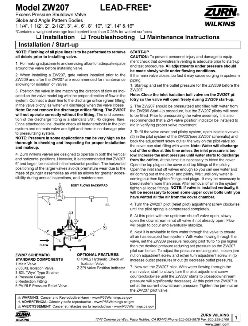
Zurn Wilkins P4000A Installation manual

1
INSTALLATION
NOTE: Prior to installation of the P4000A, ensure all debris
is ushed out the piping system.
1. During the installation of a P4000A in a sprinkler system, Under-
writer Laboratories (UL) requires NFPA 13 “Standard for Installation
of Sprinkler Systems” be followed.
2. Upon installation UL also requires that the P4000A be tested in
accordance with NFPA 13. Thereafter the valve shall be inspected,
tested, and maintained in accordance to NFPA 25 “Standard for
the Inspection, Testing, and Maintenance of Water-Based Fire
Protection Systems”.
3. For making adjustments and servicing allow for adequate
space around the valve.
4. PositiontheP4000Ainlinematchingthedirectionofowas
indicatedonthevalvemodeltagwiththeproperdirectionofow
in the system. Once attached to line double check all fasteners
are tight and there is no damage prior to pressurizing system.
NOTE: Pressure in some applications can be very high so be
thorough in checking and inspecting for proper installation
and makeup.
WARNING: Supply adequate drainage on the discharge of
the P4000A. To avoid water damage, valve must be plumbed
to a safe drain.
5. Zurn Wilkins valves are designed to operate in both the verti-
cal and horizontal positions.
START-UP
CAUTION: To prevent personnel injury and damage to equip-
ment check that downstream venting is adequate prior to
start-up and test procedures. All adjustments under pressure
should be made slowly.
Installation  Start-up  Maintenance Instructions
ZURN WILKINS
1747 Commerce Way, Paso Robles, CA 93446 Phone:855-663-9876 Fax:805-238-5766
®
1. Turn the adjustment screw clockwise until the valve spring
is compressed fully.
Caution: Do not over tighten the adjustment screw to pre-
vent damaging the valve.
2. With the inlet of the P4000A pressurized slowly turn the
adjustmentscrewcounterclockwiseuntiltherstsignofwater
ow.Eitherlistencarefullytothevalveforwateroworlook
through a downstream sight glass.
3. The valve is set to relieve pressure at the current inlet
pressureattherstsignofwaterowthroughthereliefvalve.If
the desired set pressure is different than current inlet pressure
use the table below. Turn the adjustment screw clockwise to
increase set pressure or counterclockwise to decrease set pres-
sure. Add or subtract from the current inlet pressure by turning
the adjustment screw the number of turns required to reach the
desired set pressure based on the adjustment table.
Note: The valve must be set 10 psi greater than the maxi-
mum anticipated system pressure.
Installation / Start-up
DESCRIPTION
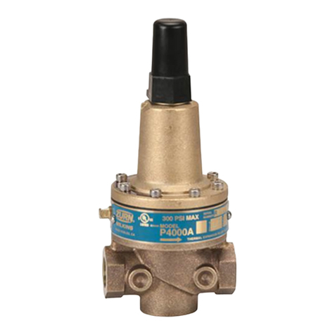
TheZurnWilkinsP4000AThermalExpansionReliefValveis
a direct acting relief valve. The P4000A uses a spring to force
the plunger down upon a seat causing the valve to be normally
closed. The P4000A can be set to relieve pressures from 50
to200psiandtheP4000AHRfrom150to300psi.Whenthe
inlet pressure reaches the set pressure point it pushes up on
the diaphragm which pulls the plunger off the seat. The valve
openstorelievepressureattheinletandallowswatertoow
downstream. The P4000A opens and closes within a close
pressure range of the set pressure.
All the instructions and references apply to both models, P4000A
&P4000AHR. P4000A
®
Model P4000A & P4000AHR
ThermalExpansionReliefValve
1/2" & 3/4"
www.zurn.com
ReliefPilot
AdjustmentRange
Pressure Change per
Turn (PSI)*
50 - 200 23
150 - 300 28.5
*Note: Pressure change per turn is approximate. Use a
gauge at the inlet of P4000A to set /check relief pressure.
4. To verify proper operation of the P4000A, view the valve
during normal operation and check the valve for relief setting.
Adjustments can be made at anytime.
NOTICE: Annual inspection and maintenance is required of all plumbing system components. To ensure proper perfor-
mance and maximum life, this product must be subject to regular inspection, testing and cleaning.
P4000AHR
FM
APPROVED
2ZURN WILKINS
1747 Commerce Way, Paso Robles, CA 93446 Phone:855-663-9876 Fax:805-238-5766
Open Regulating Operation
The Inlet pressure pushes upward on the diaphragm via the internal
sensing port. Once the upward force on the diaphragm is greater than
the compression force of the spring the plunger will move up off the
seatallowingwaterow.
Drip Tight Closing Operation
The compressed spring forces the plunger on
the seat creating a drip tight seal.
Operation
®
www.zurn.com
Operation
The Zurn Wilkins P4000A is a direct acting, spring controlled, pressure relief valve which opens from the force of upstream pres-
sure pushing up on the internal diaphragm. The relief set pressure can be easily adjusted by altering the compression force on
the spring in the bell. Once upstream pressure rises above the set pressure the diaphragm will further compress the spring on top
of the diaphragm allowing the plunger to rise off the seat and water to flow. When the upstream pressure drops back down below
the set pressure the compressed spring will force the plunger back on the valve seat sealing the valve drip tight. The valve will
open and close drip tight near the relief set pressure.
Maintenance Instructions
TheP4000APressureReliefValvemaybeinstalledinany
position.Theowdirectionisshownbelow.Flowgoesfromthe
narrow side to the wide side of the cast body.
Disassembly
Prior to disassembly, relieve all pressure in the system and then
remove the P4000A.
1. Secure valve body and turn the adjustment screw all the
way out.
2.Nextremove8socketheadscrewsaroundthebellusinga 
5/32”hexkey.Notelocationoftag/inlet.Removethebell,the
spring, and 2 spring discs.
3.Removethespacer,buttakecarenottolosethesmallo-ring
between spacer and body. Use a 12mm socket or adjustable
wrench on the diaphragm and plunger nuts to disassemble the
plunger/diaphragm assembly. Unscrew one end of the stem.
4. At this point slide the plunger/diaphragm assembly out of
the spacer.
5. Use soft jaws or a towel and pliers to clamp the stem.
Be careful not to scratch the stem as this is an o-ring
DIRECTION
OF
FLOW
INLET OUTLET
surface. Use an adjustable wrench on the opposite nut to re-
move the remaining plunger/diaphragm assembly.
6. The parts removed from the disassembled diaphragm and
plunger assembly are a plunger, small washer, 2 o-rings , 2 nuts,
a medium washer, a large washer, diaphragm, and lock washer.
7. Use a small pin or nail to carefully remove the o-ring on the
inside through hole of the spacer.
8. After complete disassembly thoroughly clean and inspect
allcomponentsbeforereassembly.Replacepartsasnecessary
after inspection.
9. The pilot seat generally does not need to be removed, but if
after inspection it requires replacement it can be removed with
a 1-1/16” socket.
P4000A Valve
Reassembly
ReassemblyoftheP4000Aisthereverseofdisassembly.
1. Carefully install a new o-ring in the through hole of the spacer.
2. Place the medium washer (with round outer edge toward
the diaphragm) on the side of the stem with the chamfered tip.
3. Follow the washer by putting on a new o-ring, new dia-
phragm, large washer (with the inner step against the dia-
phragm), lock washer, and 5/16” nut (chamfered side away
from diaphragm) then hand tighten.
4. Slide the stem through the spacer with the diaphragm
assembly on the spacer side with a circular groove on the top
surface.
3
ZURN WILKINS
1747 Commerce Way, Paso Robles, CA 93446 Phone:855-663-9876 Fax:805-238-5766
®
www.zurn.com
5. On the other side of the stem place the small washer,
o-ring, plunger (with the rubber facing away from the
spacer), and nut.
6. Use adjustable wrenches to tighten the plunger and
diaphragm nuts.
7. Place new sensing hole o-ring in small hole on the
spacer.
8. Install the spacer assembly on to the body with the plunger
sitting on the valve seat.
ITEM DESCRIPTION
13x8-16JamHexNutSS
2 Adjustment Cover
33/8-16 Adjustment Bolt
4 Spring Bell
5 Spring
6 Spring Disc
75/16" Internal Tooth Lock Washer, SS
8 Diaphragm
9O-ring
10 ReliefValveStem
11 5/16" Flat Washer, SS
12 O-ring
13 ReliefPlungerAssy.
14 O-ring
15 1/2"ReliefValveBody
16 5/16-18 Diaphragm Nut, SS
17 ReliefValveSeat
18 O-ring
19 O-ring
20 1/8" NPT Plug
21 ReliefValveSpacer
22 ReliefLowerDiaphragmWasher
23 Tag
24 10-32 X 1-1/2" Screw
25 ReliefUpperDiaphragmDisc,SS
Maintenance Instructions
23
14
24
6
25
8
22 9
10
17
14
16
15
11
12
23
7
19
6
5
18
20
13
21
9. Place a spring disk on the stem, then the spring, another
spring disk and bell.
10. Insert socket head cap screws into bell holes and thread
into valve body. Place model tag on the four screws that
straddle the body inlet. Tighten all screws in a cross pattern.
11. Install adjusting screw by hand with jam nut. Set valve once
reinstalled into system. For further assistance or
ordering replacement parts go to www.zurn.com or call
product support 877-222-5356.
Table 1
4
ISP4000A(REV.11/13) www.zurn.com
Troubleshooting
Proposition 65 Warning This product contains chemicals known to the State of California to cause cancer or birth defects
or other reproductive harm.
WARRANTY:ZURNWILKINSValvesareguaranteedagainstdefectsofmaterialorworkmanshipwhenusedfortheservicesrecommended.If
inanyrecommendedservice,adefectdevelopsduetomaterialorworkmanship,andthedeviceisreturned,freightprepaid,toZURNWILKINS
within12monthsfromdateofpurchase,itwillberepairedorreplacedfreeofcharge.ZURNWILKINS’liabilityshallbelimitedtoouragreement
to repair or replace the valve only.
Problem Possible Causes Corrective Action
1.Valvenotopening 1. The spring is over compressed 1. Loosen the adjusting screw
(Valvenotrelievingpressure)
2. Foreign matter obstruction 2. Disassemble and remove obstruction, replace parts as
necessary
3. Damaged diaphragm or stem o-rings 3. Disassemble and replace diaphragm or o-rings
4. Stem dragging on spacer 4. Disassemble valve, and check for scale or damage on stem
and spacer o-ring
5. Plugged sensing Port/sensing line 5. Check sensing line and/or port and remove obstruction
6.Valveinstalledbackward 6. Compare valve body with diagram on page 2 for correct
orientation
2.Valvenotclosing 1. Weak or no spring compression 1. Turn adjusting screw in to increase relief pressure
(Valvedrippingorrelievingpressure
below set pressure)
2. Spring damaged 2. Disassemble and replace spring as needed
3. Spring discs out of place 3. Disassemble and replace or adjust spring disc as
needed
4. Stem dragging on spacer 4. Disassemble valve, and check for scale or damage on stem
and spacer o-ring
5. Cut, worn or chipped plunger seal,
seat or plunger o-ring
5. Check plunger surface, seat and o-ring. Clean/replace as
needed
3. Leakage from valve 1. Damaged diaphragm, stem or spacer
o-ring
1. Disassemble and replace damaged part as needed
2. Ports not sealed 2.Removeandreinstallportttings,useTeontapeorpipe
sealant to ensure good seal
3. Loose diaphragm nut / bell screws 3. Disassemble and re-tighten the diaphragm nut or bell screws
ZURN WILKINS
1747 Commerce Way, Paso Robles, CA 93446 Phone:855-663-9876 Fax:805-238-5766
®

This manual suits for next models

1

Other Zurn Wilkins Control Unit manuals

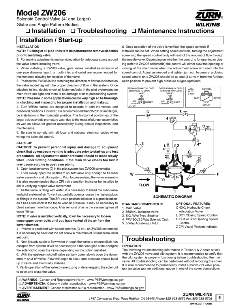
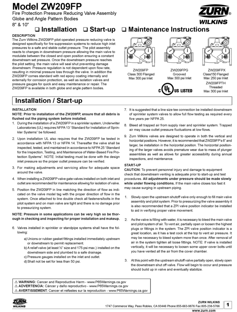
Zurn Wilkins ZW209FP Installation manual

Zurn Wilkins

Zurn Wilkins ZW209FP Installation manual

Zurn Wilkins 375 User manual

Zurn Wilkins

Zurn Wilkins 375 User manual

Zurn Wilkins ZW215FP Installation manual

Zurn Wilkins

Zurn Wilkins ZW215FP Installation manual

Zurn Wilkins P4000AHR Installation manual

Zurn Wilkins

Zurn Wilkins P4000AHR Installation manual

Zurn Wilkins ZW205 Technical specifications

Zurn Wilkins

Zurn Wilkins ZW205 Technical specifications

Zurn Wilkins 375 User manual

Zurn Wilkins

Zurn Wilkins 375 User manual

Zurn Wilkins ZW209 Manual

Zurn Wilkins

Zurn Wilkins ZW209 Manual

Zurn Wilkins ZW207 Manual

Zurn Wilkins

Zurn Wilkins ZW207 Manual

Zurn Wilkins 4-ZW207 Manual

Zurn Wilkins

Zurn Wilkins 4-ZW207 Manual

Zurn Wilkins ZW204 Manual

Zurn Wilkins

Zurn Wilkins ZW204 Manual

Zurn Wilkins ZW206 User manual

Zurn Wilkins

Zurn Wilkins ZW206 User manual

Zurn Wilkins ZW209Q Manual

Zurn Wilkins

Zurn Wilkins ZW209Q Manual

Zurn Wilkins 6-ZW209HP Manual

Zurn Wilkins

Zurn Wilkins 6-ZW209HP Manual

Zurn Wilkins ZW209H User manual

Zurn Wilkins

Zurn Wilkins ZW209H User manual

Zurn Wilkins ZW209FP Installation manual

Zurn Wilkins

Zurn Wilkins ZW209FP Installation manual

Zurn Wilkins ZW205FP Installation manual

Zurn Wilkins

Zurn Wilkins ZW205FP Installation manual

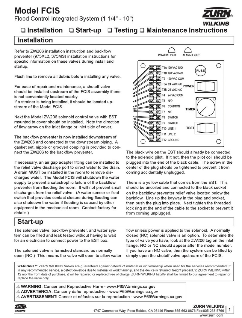
Zurn Wilkins FCIS User manual

Zurn Wilkins

Zurn Wilkins FCIS User manual

Popular Control Unit manuals by other brands

Burkert 0641 operating instructions

Burkert

Burkert 0641 operating instructions

Vansco VMM3120 user guide

Vansco

Vansco VMM3120 user guide

STIEBEL ELTRON FEB Operation and installation manual

STIEBEL ELTRON

STIEBEL ELTRON FEB Operation and installation manual

ABB HD5-B-901 Original instructions

ABB

ABB HD5-B-901 Original instructions

Böhmer BBF operating instructions

Böhmer

Böhmer BBF operating instructions

M-system R3Y-DS8N instruction manual

M-system

M-system R3Y-DS8N instruction manual

GEA DHV operating instructions

GEA

GEA DHV operating instructions

ICMA TAS001 manual

ICMA

ICMA TAS001 manual

Teleco TVPLA868CC2EN manual

Teleco

Teleco TVPLA868CC2EN manual

Align 3GX V2.1 Setup

Align

Align 3GX V2.1 Setup

HumanTechnik Signolux MV-1 instruction manual

HumanTechnik

HumanTechnik Signolux MV-1 instruction manual

Savant CLI-10K4IN-00 Quick reference guide

Savant

Savant CLI-10K4IN-00 Quick reference guide

Sfar SFAR-S-ETH user manual

Sfar

Sfar SFAR-S-ETH user manual

Keysight N2125A user guide

Keysight

Keysight N2125A user guide

Mankenberg DM 762 ATEX Original operating manual

Mankenberg

Mankenberg DM 762 ATEX Original operating manual

Bosch B426 quick start guide

Bosch

Bosch B426 quick start guide

TriangleTube PRESTIGE TriMax PTRKIT205 quick start guide

TriangleTube

TriangleTube PRESTIGE TriMax PTRKIT205 quick start guide

UNICORECOMM UM220-IV M0 user manual

UNICORECOMM

UNICORECOMM UM220-IV M0 user manual

manuals.online logo
manuals.online logoBrands
  • About & Mission
  • Contact us
  • Privacy Policy
  • Terms and Conditions

Copyright 2025 Manuals.Online. All Rights Reserved.