Novatek-electro TK-415 User manual
“NOVATEK-ELECTRO” LTD.
Sequential and Combination Timer TK-415
with RS-232 communication
OPERATION MANUAL
WWW.NOVATEK-ELECTRO.COM/EN
2011
www.novatek-electro.in
15 channel Traffic Controller TK-415
Sequential cum Combination timer TK-415

2
1. GENERAL PROVISIONS
1.1. BASIC FUNCTIONS
- microprocessor controlled.
- simple change-over between sequential and combination timer.
- 7-segment LED indications.
- selectable 3 time ranges (SEC:MSEC, MIN:SEC, HRS:MIN)
- cascade connection of several devices for extended total number of channels.
- memorization of program and device mode after switching off and program operation restart
from point of stoppage.
- inputs for timer start and pause control.
- fast resetting.
- copy of settings.
- program can be executed only one time or/and cyclic operation possible.
- RS-232 communication port for programming and possibility of operation through PC/ DCS
(free PC software).
1.2. BASIC TECHNICAL BRIEF
Table 1.1.
Supply voltage, V
85 to 270 AC/DC
Frequency range, Hz
47-63
Power consumption, VA
8
Time setting range
From 100ms to
99hr59min.
Commutation accuracy
±0.1% + 20ms
Number of channels
15
Number of combinations per channel (ON/OFF)
8
Operating temperature range, °C
from -25 through +55
Storage temperature, °С
from -35 through +80
Humidity (non condensing)
95% @ 40°С
Insulation resistance
>100МOhm @ 500V
DC
Dimensions, mm
85.8 х 156.2 х 56.8
Indication of load relay
Yes
Protection level
ІР20
Climatic resistance version
УХЛ4
Data memory, years, minimum
10
Output Relays, CO
15
Channel contacts type
normally open
contact (NO)
3
Characteristics of output channels
сos ϕ
Maximum current at
U~250V
Maximum capacity
Maximum current at
Uconst=24V
1.0
10 A
2500 VA
10 A
0.4
4 A
1000 VA
Commutation resource of output contacts:
- mechanical resource
- electric resource 10A 250V AC, times, minimum
- electric resource 10A 24V DC, times, minimum
- electric resource 4A 250V AC (сos ϕ = 0,4 ), times, minimum
107
100 000
30 000
100 000
Signal «Start»
Contact Closure S1
and S2 maximum at
150 milliseconds
Mounting
onto standard 35 mm
DIN-rail
Mounting position
any
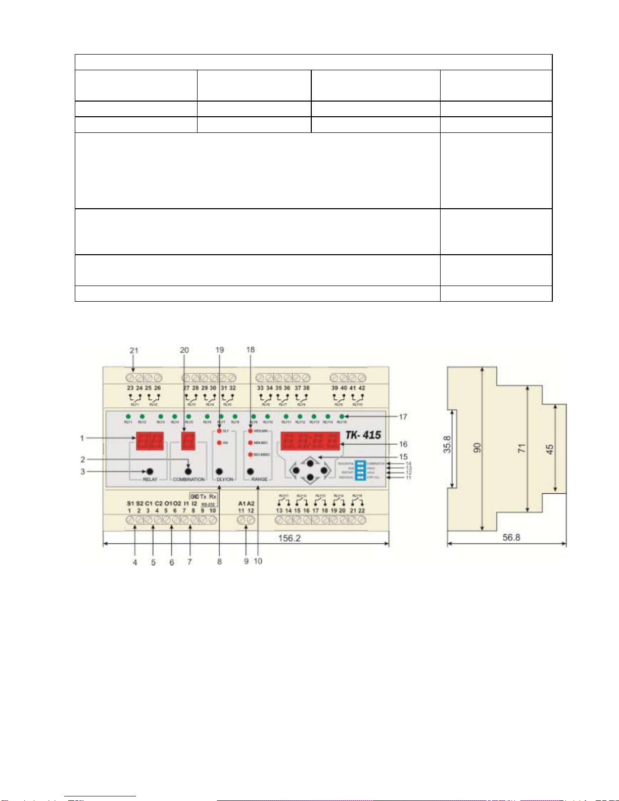
1.3. EXTERNAL VIEW AND DIMENSIONS
Figure 1.1.
1. Indicator for selected channel.
2. COMBINATION
Button of selection of combination DLY/ON of active channel in case of timer operation in
combination mode.
3. RELAY
Button of selection of channel for programming or channel information displaying.

4
4. S1/S2
Inputs of timer start for program execution. For start of program processing inputs S1 and S2
should be closed for 150 milliseconds. Switch RUN/PROG should be in position RUN.
5. C1/C2
Inputs of looping execution of program. If inputs C1 and C2 are closed, the program is executed
only one time. Otherwise, the program would be in cyclic mode.
6. O1/O2
Outputs of cascade connections of devices. After completion of execution of program outputs O1
and O2 are closed for 200 milliseconds.
7. I1/I2
Inputs of pause control. Zero potential between I1 and I2 suspends the program execution. After
un-shorting between I1 and I2, the execution of program is continued from the suspension time.
8. DLY/ON
Button of selection of time setting of open (DLY) or closed (ON) contacts of active channel
output.
9. A1/A2
Power inputs according to technical specifications.
10. RANGE
Button for selection of range of time programming DLY/ON according to the Table 1.2:
Table 1.2
Designation
Range
HRS:MIN
from 1 minute to 99 hours 59 minutes
MIN:SEC
from 1 second to 99 minutes 59 seconds
SEC:MSEC
from 100 millisecond to 999.9 seconds
11. INDIVID/COPY ALL
When the switch is in position INDIVID, the program will be executed for every channel
independently as it have programmed. If switch is in position COPY, during execution of the
program the values of times DLY and ON for every channel will be used from first channel.
12. RESTR/HOLD
Selection of device behavior in case of absence of external power. If the switch is in position
RESTR, the program will restart from the very beginning after restoration of power supply. If it
is in position HOLD, the timer settings at the moment of emergency switching will be stored in
nonvolatile memory and the program will be restarted after restoration of power supply.
13. RUN/PROG
The selection of PROGRAM or RUN timer mode.
5
14. SEQ/COMB
Selection of timer principle of operation: sequential or combination.
15. Buttons for selection of position and setting of values on Time indicator 16.
16. Time Indicator.
17. Indicator displaying closed/open mode of channel contacts.
18. Indicator of selected time range (see Table1.2).
19. Indicator displaying current mode of time programming of open (DLY) or closed (ON) contacts
on Time indicator.
20. Indicator of selected combination for combination timer.
21. Terminals for load connection to output channel contacts.
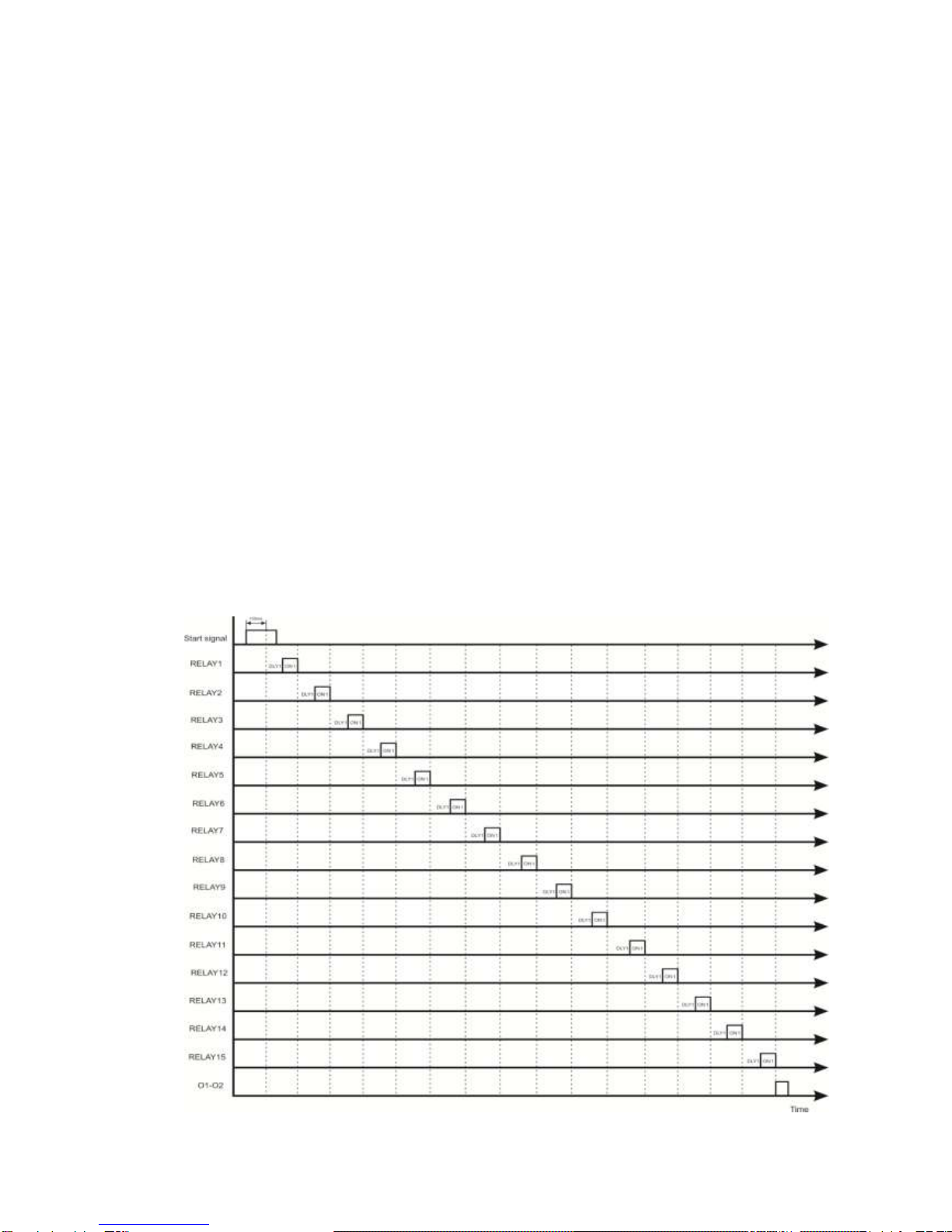
1.4. TIME DIAGRAMS
I. Sequential timer, mode of execution of one cycle of program (inputs C1 and C2 are shorted):
Diagram 1.1.

6
II. Sequential timer, cycling mode (inputs C1 and C2 are not shorted):
Diagram 1.2.
7
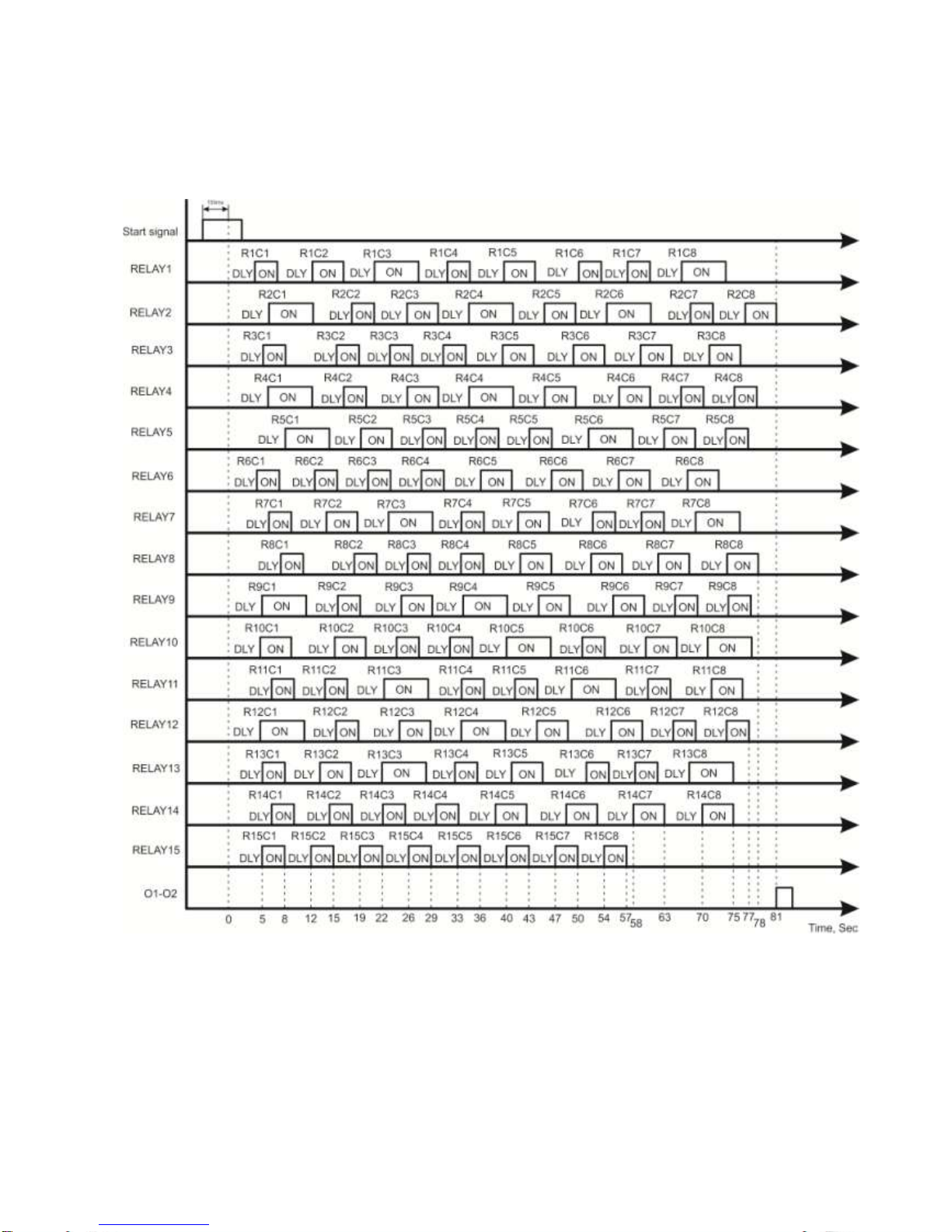
III. Combination timer, mode of execution of one cycle of program (inputs C1 and C2 are
shorted):
Diagram 1.3.
Where, for example, R2C5 means the fifth combination of the second channel (relay).

8
IV. Combination timer, cycle mode (inputs C1 and C2 are not shorted):
Diagram 1.4.
9
2. SETTING AND OPERATION
2.1. CONNECTION
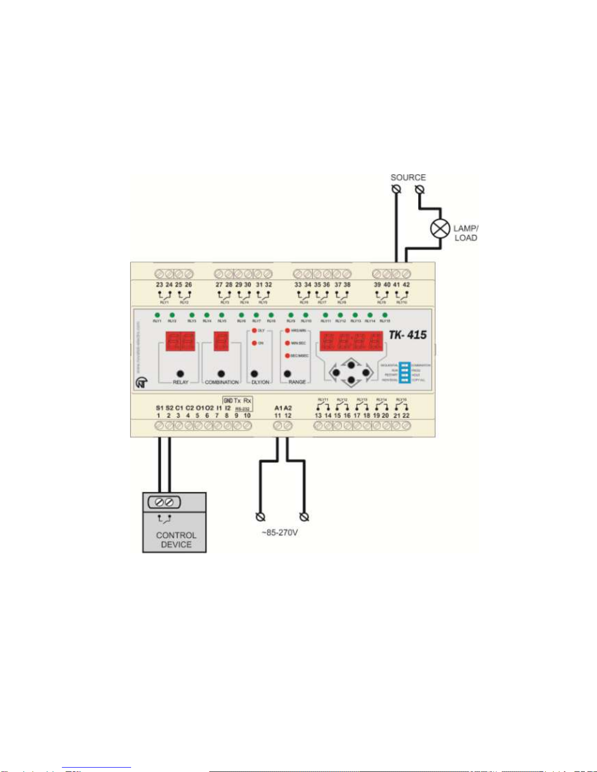
The Figure 2.1 represents the typical method of timer connection. Load is connected to output of
channel RLY10 as an example.
Figure 2.1. Typical method of timer connection.

10
The Figure 2.2 represents the method of cascade connection of three timers. Please, pay attention
that inputs C1 and С2 are shorted.
Figure 2.2. Cascade connection of timers.
Method of cascade connection of timers with possibility of cycle work (upon completion of
operation of last timer the first one starts operating) is represented at Figure 2.3:
Figure 2.3. Cycle operation of timers in case of cascade connection.
2.2. SAFETY MEASURES
ATTENTION! Connection of inputs S1/S2, C1/C2, I1/I2, to external power sources may cause
failure of device. These inputs should be connected only to insulated contacts of relay or switches.
Table of contents
Other Novatek-electro Timer manuals


