Novatron Xsite EASY 100022 User manual

XSITE EASY
INSTALLATION MANUAL
Ver. 1.01 / 4 Feb 2015

TABLE OF CONTENTS
1 INTRODUCTION 1
1.1 Safe y ins ruc ions..................................................................................................................3
1.2 Produc overview...................................................................................................................6
1.3 Handling of he sys em..........................................................................................................8
1.4 Transpor a ion and s orage....................................................................................................8
1.5 Suppor and main enance......................................................................................................8
2 INSTALLATION OF COMPONENTS 9
2.1 Componen s inside he cabin.................................................................................................9
2.2 Inclina ion sensors and laser receiver..................................................................................10
2.2.1 Til bucke sensor.........................................................................................................13
2.2.2 Bucke sensor...............................................................................................................16
2.2.3 Laser receiver...............................................................................................................17
2.2.4 S ick, main boom, and ex ra boom sensors..................................................................18
2.2.5 Frame sensor...............................................................................................................19
2.3 Finalizing he ins alla ion......................................................................................................19
2.3.1 Power cord...................................................................................................................20
3 INSTALLATION DATA 21
3.1 Bucke leng hs.....................................................................................................................21
3.2 Linkage leng hs....................................................................................................................22
3.3 Laser receiver leng hs..........................................................................................................22
3.4 Boom leng hs....................................................................................................................... 23
3.5 Ro a ion cen re poin offse s................................................................................................24
4 CALIBRATION 24
4.1 Frame sensor calibra ion.....................................................................................................25
4.2 S ick sensor calibra ion........................................................................................................25
4.3 Main boom sensor calibra ion..............................................................................................30
4.4 Ex ra boom sensor calibra ion..............................................................................................31
4.5 Boom line accuracy es .......................................................................................................31
4.6 Bucke moun calibra ion......................................................................................................31
4.6.1 Quick coupler............................................................................................................... 32
4.6.2 Linkage......................................................................................................................... 32
4.7 Finalizing he calibra ion......................................................................................................32
APPENDICES
EC Declara ion of Conformi y
FCC Declara ion of Conformi y
1 INTRODUCTION
This documen is he ins alla ion manual for he Xsi e Easy excava or guidance sys em. Please
read his manual comple ely, paying special a en ion o he safe y ins ruc ions, and make sure you
unders and all he informa ion in he manual before using he sys em. Keep he manual available
for fu ure reference.
System software version
This manual applies o sof ware version 2.2.
Manufacturer's contact information
Nova ron Oy
Myllyhaan ie 6 E
33960 Pirkkala, Finland
Tel: +358 (0)3-357 26 00
E-mail: sales@nova ron.fi, service@nova ron.fi, echsuppor @nova ron.fi
Web: www.nova ron.fi
Conformity to EU directives (European Union)
This produc is in conformi y wi h EMC (2004/108/EC), RoHS (2002/95/EC), and WEEE
(2002/96/EC) direc ives. This produc may no be disposed of oge her wi h unsor ed household
was e - i mus be properly recycled according o local regula ions.
Conformity to FCC rules (North America)
This produc complies wi h par 15 of he FCC rules.
isclaimer
The manufac urer does no accep any liabili y for damages caused by:
Inappropria e assembly and/or ins alla ion
Non-observance of he ins ruc ion manual
Non-in ended and improper use
Use beyond opera ion limi s
Use by insufficien ly qualified and rained personnel
Use of unau horized spare par s and accessories
Decons ruc ing and/or rebuilding of he produc
XSITE EASY | Ins alla ion manual | Page 1 of 34

Instruction manual
This ins ruc ion manual con ains basic informa ion o be considered when using and main aining
he produc . Observing all securi y ins ruc ions and guidelines given here is indispensable for
secure opera ion. This ins ruc ion manual mus herefore be read and applied, wi hou fail, by any
person assigned wi h working processes o do wi h he machine, such as opera ion, faul finding
and main enance.
This manual is o be considered a par of he produc and as such mus be passed on o relevan
hird par ies or subsequen owners. I mus be permanen ly kep a he usage si e and be available
for he opera ing personnel. Fur hermore, general safe y regula ions, manufac urer's safe y
regula ions and local acciden preven ion regula ions for he area in which he produc is being
used, mus also all be observed.
The produc is available wi h a number of sensor combina ions. If your sys em is no equipped wi h
some of he sensors or o her componen s described in his manual, hose sec ions of he manual
are no applicable o you.
We are eager o ensure ha his ins ruc ion manual is correc and up- o-da e. To main ain our
echnological edge, i may be necessary o under ake modifica ions o he produc and i s
opera ion wi hou prior no ice. If you are using a newer or older version of he produc or sof ware
han ha described in his manual, he informa ion herein may no longer be applicable. If his is he
case, your local dealer will be happy o provide you wi h a new manual. We do no accep liabili y
for dis urbances, failures or damages resul ing from he use of an ou -of-da e manual.
The ex and graphics wi hin his manual have been colla ed wi h he grea es possible care.
However, we will no be held liable for possible errors or consequences arising from hem. Should
you wish o make sugges ions regarding his manual or poin ou possible errors, please con ac
your local dealer. We will gladly ake your ideas and sugges ions in o considera ion.
Explanation of symbols
Warning no ices are marked in his ins ruc ion manual wi h symbols. Under all circums ances
observe hese no ices and proceed carefully o preven acciden s, personal injuries, and ma erial
damages.
Indica es a hazardous si ua ion. If no avoided, could resul in dea h, serious
injury, or ma erial damages.
Emphasizes useful ips, recommenda ions and o her informa ion for efficien and
rouble-free opera ion.
XSITE EASY | Ins alla ion manual | Page 2 of 34

1.1 Safe y ins ruc ions
This sec ion ou lines all impor an safe y ma ers concerning he op imal safe y of personnel as well
as failure-free opera ion. These ins ruc ions shall enable users o recognize po en ial risks of use
and, as far as possible, preven hem in advance. Every user has o unders and and observe hese
ins ruc ions.
The produc mus no be solely relied on for he opera ion of he machine. The opera or
mus main ain a proper view of he opera ing area a all imes.
Conventional use
The produc has been exclusively designed and cons ruc ed for conven ional use as described
here.
Posi ioning he bucke of an excava or wi h he help of gravi a ion sensors, laser receiver,
or o her sensors.
Indica ion of he posi ion of he measuring poin o he user.
Comparison of he posi ion of he measuring poin wi h various ypes of reference
informa ion.
Any o her use no lis ed here, as well as any applica ion no complying wi h he echnical da a, is
no considered conven ional use.
Improper use
Non-conven ional use
Exceeding he limi values given on he da a shee
Use of he produc wi hou ins ruc ions
Use of he produc beyond he limi s of use
Invalida ion of safe y equipmen
Removal of indica ing or warning labels
Opening, rebuilding or al era ion of he produc
Use of he produc in spi e of obvious defec s or damages
Use of he produc wi h unau horized accessories from o her manufac urers
Use of he produc a insufficien ly secured cons ruc ion si es
Alteration and rebuilding of the product
To preven risks and ensure op imal performance, al era ions, a achmen s or rebuilding of he
produc may no be carried ou wi hou he manufac urer’s explici permission.
The foremans’s responsibility
The produc is used in he indus rial sec or. The foreman of he produc is herefore subjec o legal
responsibili ies for opera ional safe y. In addi ion o he opera ional safe y ins ruc ions in his
manual, he relevan safe y, acciden preven ion and environmen al pro ec ion regula ions for he
area in which he produc is opera ing mus also be observed.
XSITE EASY | Ins alla ion manual | Page 3 of 34

Par icularly applicable:
The foreman mus make sure he is aware of he curren opera ional safe y regula ions and,
in a risk assessmen , be able o de ec addi ional risks caused by he special working
condi ions a he usage si e of he produc . These risks mus be compiled in he form of
wri en ins ruc ions, which mus hen be kep near o he produc and permanen ly be
available for he persons working wi h i
The foreman mus clearly define he responsibili ies of he personnel wi h regard o he
appliance
The foreman mus ensure ha he con en s of he ins ruc ion manual have been fully
unders ood by he opera ing personnel
The informa ion in he ins ruc ion manual mus be observed horoughly and wi hou
excep ion
The foreman mus ensure ha all main enance, inspec ion and assembling processes are
carried ou by qualified, specialized personnel, and ha such personnel have fully
acquain ed hemselves wi h he produc and i s applica ion by carefully s udying he produc
manuals
The foreman mus inform he manufac urer or he au horized dealer if any safe y defec s
are found or occur during opera ion
Special risks
Epilepsy warning
Some people are suscep ible o epilep ic seizures or loss of consciousness when
exposed o cer ain flashing ligh s or ligh pa erns. Immedia ely discon inue use and
consul your doc or if any of he following symp oms occur while using he produc :
dizziness, blurred vision, eye or muscle wi ches, loss of consciousness, disorien a ion
or any involun ary movemen or convulsion.
Risks caused by electric current
When working close o elec rici y sys ems (for example overhead powerlines), here is
a danger of dea h due o elec ric shock. Keep sufficien safe y dis ance o elec rical
sys ems.
Moving components
Keep o her persons away from he working range of he machine and he ool.
Remove objec s from he working range of he machine and he ool. Do no in erfere
wi h he moving componen s during opera ion.
Overhanging machine parts
Sys em componen s assembled af er he machine has lef he fac ory can increase he
ypical dimensions of he machine. Being unaware of his can lead o injuries and
ma erial damages.
XSITE EASY | Ins alla ion manual | Page 4 of 34

Risk of injury caused by malfunction
Uncon rolled machine ac ions caused by he malfunc ion of a sys em componen can
lead o severe personal injuries or cause ma erial damage wi hin he machine’s
working range. Ensure ha he machine is opera ed, con rolled and inspec ed by a
qualified and experienced opera or, who is capable of carrying ou emergency
measures, such as an emergency s op.
Lacking instruction
Lacking or insufficien ins ruc ion can lead o opera ing errors or incorrec use. This can
lead o severe personal injuries, as well as significan ma erial and environmen al
damage. Observe he manufac urer’s safe y ins ruc ions and he foreman’s direc ives.
Risk of injury caused by insufficient safeguarding
Insufficien safeguarding of he cons ruc ion si e and he loca ion of he componen
(for example he posi ion of he laser emi er), can lead o hazardous si ua ions on he
cons ruc ion si e and surrounding raffic. Ensure sufficien safeguarding of he
cons ruc ion si e. Ensure sufficien safeguarding of he loca ions of each single
componen . Observe he coun ry-specific safe y and acciden preven ion regula ions,
as well as he curren road raffic regula ions.
Risks caused by faulty measurement results
Faul y measuremen resul s due o use of a damaged (for example dropped) produc ,
improper use or al era ion o he produc can lead o severe ma erial damages. Do no
use produc s showing obvious signs of damage. Before re-using a componen ha has
been dropped, carry ou a es measuremen o ensure accura e readings.
Risk of injury caused by unreadable signs
In he course of ime, labels and symbols on he produc can become unrecognisable
due o dir , wear or o her damage. Labels and symbols can also ge de ached. Always
keep safe y, warning and opera ion ins ruc ions in good enough condi ion ha hey
can easily be read. Regularly check he adhesiveness of he labels and symbols on
he produc . Do no remove any labels or symbols from he produc .
Risk of injury caused by inappropriate disposal of the product
When burning plas ic par s, oxic gases ha can cause illnesses are emi ed.
Dispose he produc properly according o he curren na ional coun ry-specific
disposal regula ions. Careless disposal migh also enable unau horized persons o
improperly use he produc ; in doing so, hese persons and/or hird par ies migh be
severely injured and also pollu e he environmen . A all imes, pro ec he produc
agains access by unau horized persons.
XSITE EASY | Ins alla ion manual | Page 5 of 34

Proceeding in case of danger and accidents
Preven ive measures
Always be prepared for possible acciden s or fire
Keep firs -aid equipmen (ambulance box, blanke s e c.) wi hin reach
Familiarize all personnel wi h acciden no ifica ion and firs -aid equipmen as well as
procedures for aler ing he emergency services
Keep access rou es clear for emergency vehicles
In he even of acciden , proceed appropria ely:
1. Immedia ely shu down he produc by swi ching he power off
2. Begin firs -aid-measures
3. Recover persons ou of he hazard zone
4. Inform he responsible person a he usage si e
5. Aler medical assis ance and/or he fire brigade
6. Ensure ha access rou es are clear for emergency vehicles
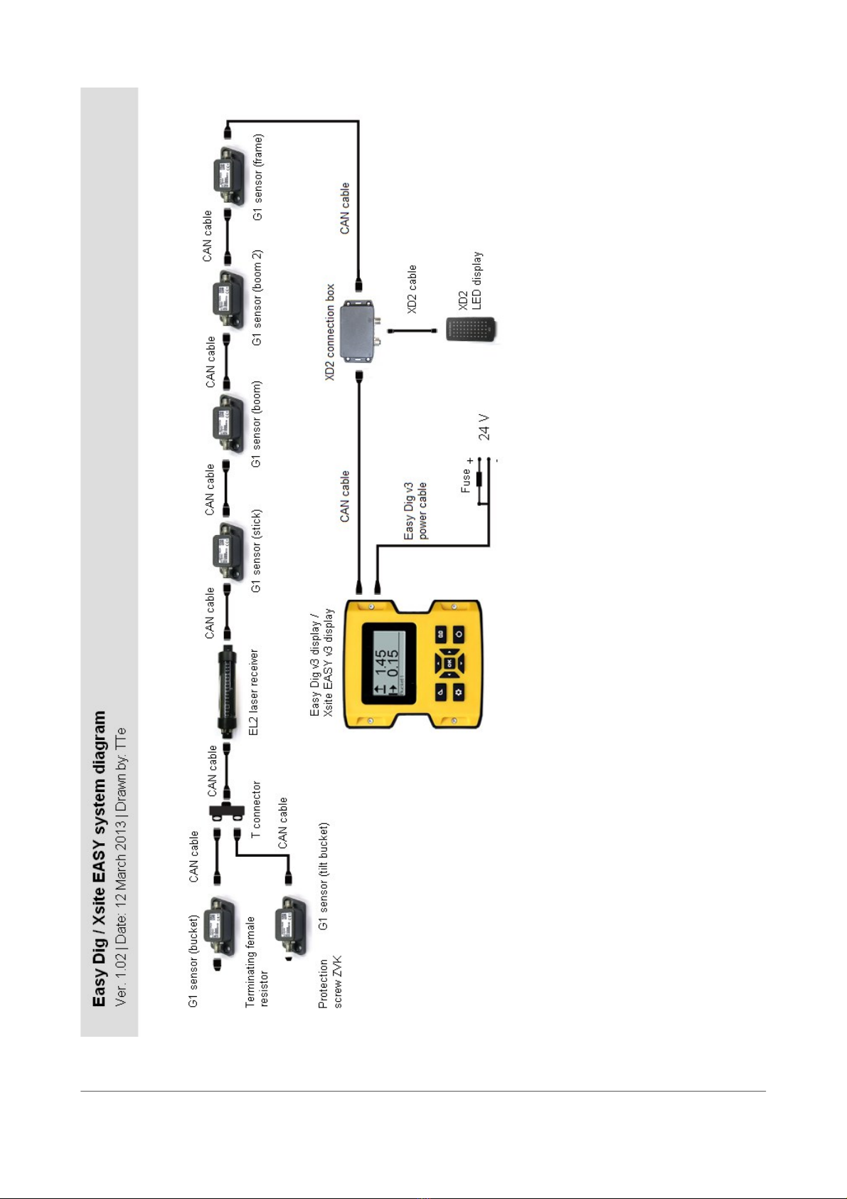
1.2 Produc overview
Xsi e Easy is a machine guidance sys em for excava ors. Xsi e Easy indica es he posi ion of he
measuring poin compared o a reference level.
The sys em con ains he following componen s by defaul (Figure 1):
1. Display uni
2. Connec ion box for LED display
3. Gravi a ion sensors for bucke , dipper s ick, main boom, and frame
The sys em can be expanded by adding he following op ional accessories (Figure 1):
Til bucke sensor
Dual block boom sensor
Laser receiver
LED display
XSITE EASY | Ins alla ion manual | Page 6 of 34
XSITE EASY | Ins alla ion manual | Page 7 of 34
Figure 1. Sys em diagram

1.3 Handling of he sys em
The display is no comple ely wa erproof. If he display or o her componen s are aken away from
he cons ruc ion machine, a carrying case should be used. Make sure ha he componen s are
clean and dry before placing hem in he carrying case. Also make sure ha he carrying case is
clean and dry.
1.4 Transpor a ion and s orage
When aking he equipmen o he usage si e or carrying i in he field, always ensure ha he
produc is ranspor ed in secured, sui able con ainers. Never ranspor he produc loosely in a
vehicle. Knocks and hi s can severely harm he func ioning of he produc . In case of ranspor a ion
by railway, plane or ship, always use he original packaging, ranspor con ainers and ranspor
boxes. The packaging pro ec s he produc agains hi s and vibra ion.
Only s ore he produc in well aired, dry rooms. During s orage, pro ec i agains dampness, and
use he original packaging whenever possible. Avoid s rong fluc ua ions in empera ure during
s orage. Wa er condensa ion can form gradually, harming he func ioning of he produc .
1.5 Suppor and main enance
Main enance services are provided by he manufac urer or au horised dealer. The ins alla ion and
servicing of he produc should only be carried ou by rained and qualified personnel.
For safe y reasons, only represen a ives of he manufac urer are allowed o open he
housings.
XSITE EASY | Ins alla ion manual | Page 8 of 34

2 INSTALLATION OF COMPONENTS
The chap ers below provide informa ion abou ins alla ion of he componen s
2.1 Componen s inside he cabin
When moun ing he displays, no ice he following precau ions:
Display should be moun ed so ha i is easily reachable by he opera or.
Display should no block he view ou side.
Display should no block he view o machine's in egra ed display.
Display should no preven he fron window from opening.
Display should no res ric moving of opera or's sea .
Display should no res ric access o he s eering wheel or joys icks.
A ach he Xsi e Easy display and he XD2 LED display o he fron or side window by suc ion cups
(Figure 2). Before a aching he suc ion cup, make sure ha he window is clean (use for example
isopropyl alcohol if needed) and warm (warm i up carefully if needed).
Moun he XD2 connec ion box for example behind he opera or's sea by screws or ape (Velcro,
Dual lock). Make sure ha all cables can reach o he connec ion box and ha he connec ion box
does no res ric moving of opera or's sea . Make sure ha he plas ic covers of he cabin can be
de ached wi hou unmoun ing he connec ion box.
XSITE EASY | Ins alla ion manual | Page 9 of 34
Figure 2. Example of he moun ing place of he Xsi e Easy display and he XD2 LED display
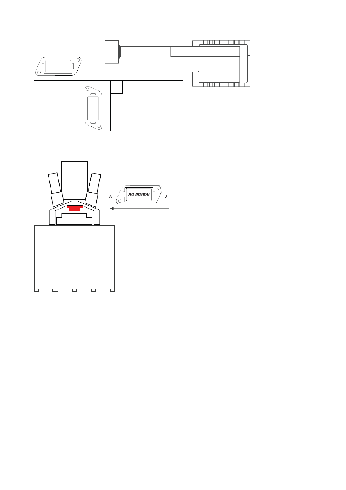
2.2 Inclina ion sensors and laser receiver
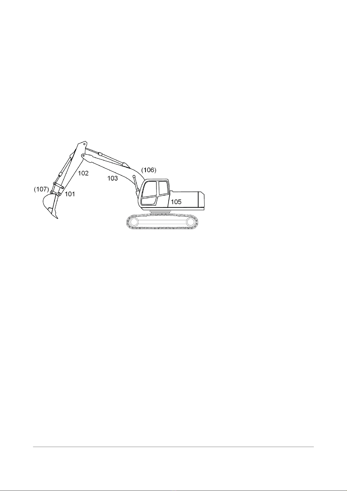
Inclina ion sensors are moun ed on he moving par s of he excava or. Sensors are labeled wi h he
following iden ifica ion numbers (Figure 3):
101. Bucke sensor
102. S ick sensor
103. Main boom sensor
10 . Not used
105. Frame sensor
106. Ex ra boom sensor (if excava or is equipped wi h dual block boom)
107. Til bucke sensor (op ional)
I is possible o change he sensor ID wi h a PC sof ware provided by Nova ron. For example if
replacing a broken sensor wi h a new one, he ID of he new sensor mus be he same as he ID of
he broken sensor.
I is no needed o align he sensors wi h he boom lines ( he line be ween wo pivo poin s).
Sof ware calibra ion correc s he devia ion from he boom line. However, some sensors require
more precise moun ing han o hers.
Sensors are moun ed in he following order:
1. Til bucke sensor (op ional)
2. Bucke sensor
3. S ick sensor
4. Main boom sensor
5. Ex ra boom sensor (op ional)
6. Frame sensor
The sensors should be moun ed where he cable from he previous sensor ends in order o avoid
loose cable on he boom. If he bucke is very greasy, ins all he il bucke sensor las o avoid
s aining of he cabin during he res of he ins alla ion procedure.
In mos cases sensors are moun ed by using bol s. However, some machine manufac urers do no
accep drilling of he boom. In hose cases, sensors are a ached o moun ing pla es by screws.
Moun ing pla es are welded on he boom.
XSITE EASY | Ins alla ion manual | Page 10 of 34
Figure 3. Sensor IDs

XSITE EASY | Ins alla ion manual | Page 12 of 34
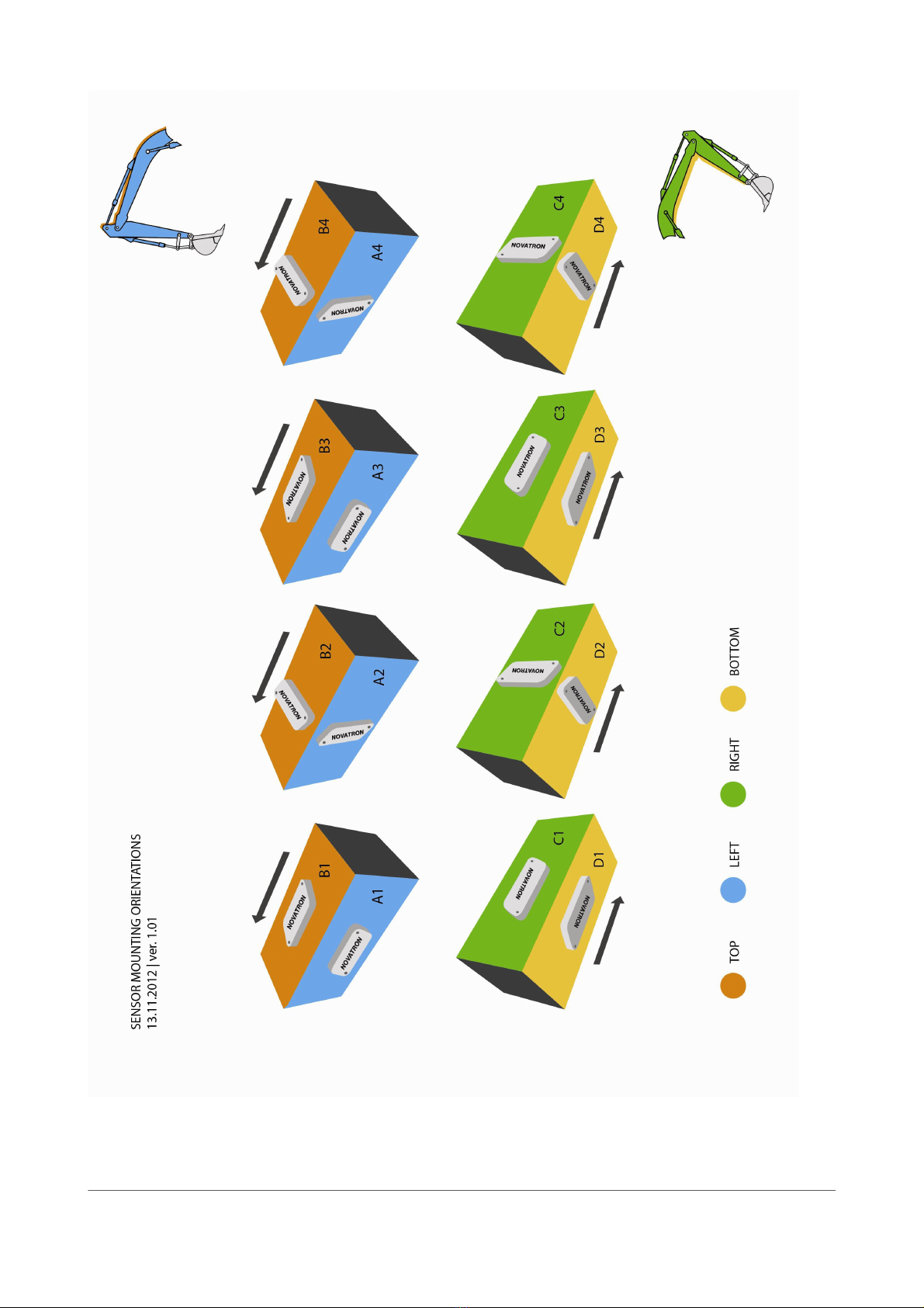
Figure 5. Moun ing orien a ions (arrow poin s forward)

2.2.1 Til bucke sensor
Movemen s of he bucke and bucke accessories have o be checked before ins alling
he sensor or sensor cables. Movemen s of he cable have o be checked af er he
ins alla ion.
The moving par of he cable has o be covered by a shield. Shielded cable from he
bucke sensor has o be connec ed wi h one or more fas eners. Moun he firs fas ener
approxima ely 15 cm from he sensor.
Til bucke sensor can be moun ed on a il ro a or, il ing quick coupler or il ing bucke .
Possible moun ing orien a ions for he il bucke sensor are
•A1: lef side, measuremen axis A poin ing forward
•B1: on he op, measuremen axis A poin ing forward
•B2: on he op, measuremen axis A poin ing righ when looking from he cabin
•B3: on he op, measuremen axis A poin ing backward
•B4: on he op, measuremen axis A poin ing lef when looking from he cabin (Figures 8
and 9)
•C1: righ side, measuremen axis A poin ing forward
•D1: a he bo om, measuremen axis A poin ing forward
•D2: a he bo om, measuremen axis A poin ing lef when looking from he cabin (Figure 7)
•D4: a he bo om, measuremen axis A poin ing righ when looking from he cabin
If possible, moun he sensor in a safe place. A shield (for example ou of s eel) can be
made for he sensor, if needed.
For an easy access o he sensor connec or, i should be close o he hydraulic hose
connec ors of he il ro a or.
Always align he il bucke sensor ei her wi h he boom line or so ha is forms a 90°
angle wi h he boom (Figure 6). Devia ion of ± 1° can be olera ed. However, he
smaller he devia ion, he be er he measuremen resul .
XSITE EASY | Ins alla ion manual | Page 13 of 34
XSITE EASY | Ins alla ion manual | Page 14 of 34
Figure 6. Alignmen of he il bucke sensor
Figure 7. Til bucke sensor on he il ing par of he il ro a or, inside he cover pla e (moun ing
orien a ion D2). Moun ing place depends on he manufac urer of he il ro a or. In his example
he sensor is moun ed upside down.
XSITE EASY | Ins alla ion manual | Page 15 of 34
Figure 8. Til bucke sensor on a il ing quick coupler (moun ing orien a ion B4)
Figure 9. Til bucke sensor on a il ing bucke (moun ing orien a ion B4)

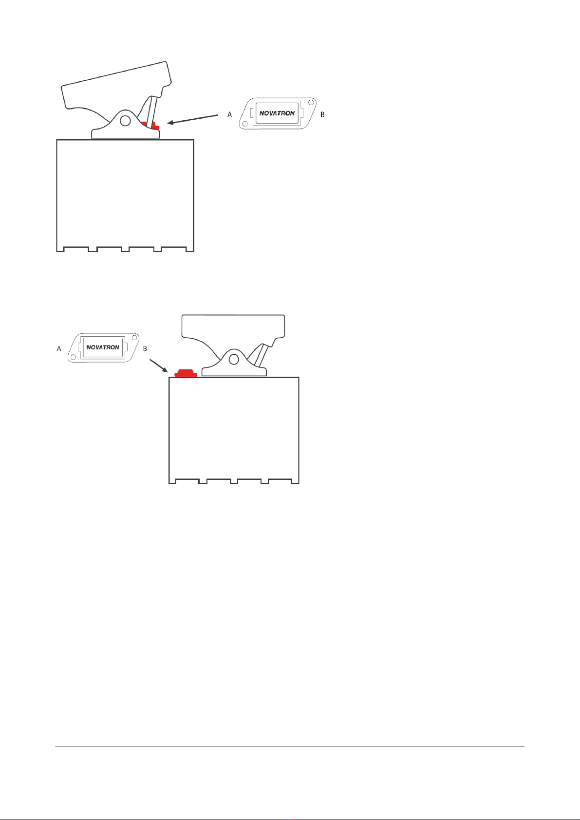
2.2.2 Bucke sensor
Movemen s of he bucke and bucke accessories have o be checked before ins alling
he sensor or sensor cables. Movemen s of he cable have o be checked af er he
ins alla ion.
The moving par of he cable has o be covered by a shield. Shielded cable from he
bucke sensor has o be connec ed wi h one or more fas eners. Moun he firs fas ener
approxima ely 15 cm from he sensor.
Bucke sensor can be ins alled on quick coupler or linkage.
Possible moun ing orien a ions for quick coupler ins alla ion are
•A1: lef side, measuremen axis A poin ing o he bucke ip (Figure 10)
•B1: on he op, measuremen axis A poin ing o he bucke ip
•B4: on he op, measuremen axis A poin ing lef when looking from he cabin
•C1: righ side, measuremen axis A poin ing o he bucke ip
When ins alling he sensor on he quick coupler, i is no necessary o align he sensor exac ly wi h
he line from he bucke pin o he bucke ip (Figure 10). Bucke calibra ion correc s he devia ion
from he line. However, he devia ion should be as small as possible. No e ha when changing he
bucke , he devia ion also changes.
Possible moun ing orien a ions for linkage ins alla ion are
•A1: lef side, measuremen axis A poin ing forward (Figure 11)
•B1: on he op, measuremen axis A poin ing forward
•C1: righ side, measuremen axis A poin ing forward
When ins alling he sensor on he linkage, align he sensor wi h he line be ween he linkage pins
wi hin an accuracy of ±10°.
XSITE EASY | Ins alla ion manual | Page 16 of 34
Figure 10. Ins alla ion on he inner or ou er surface of he quick coupler (moun ing orien a ion A1)
2.2.3 Laser receiver
Laser receiver is moun ed connec ors poin ing downwards on he lef side of he s ick aligned
exac ly wi h he line be ween he s ick pin and he bucke pin (Figure 12). Laser receiver should be
moun ed in a shel ered place if possible. Laser receiver should be moun ed on he lower par of he
s ick, so ha i is no needed o lif he ransmi er unnecessarily high.
XSITE EASY | Ins alla ion manual | Page 17 of 34
Figure 12.Laser receiver
Figure 11. Ins alla ion on he inner or ou er surface of he linkage (moun ing orien a ion A1)

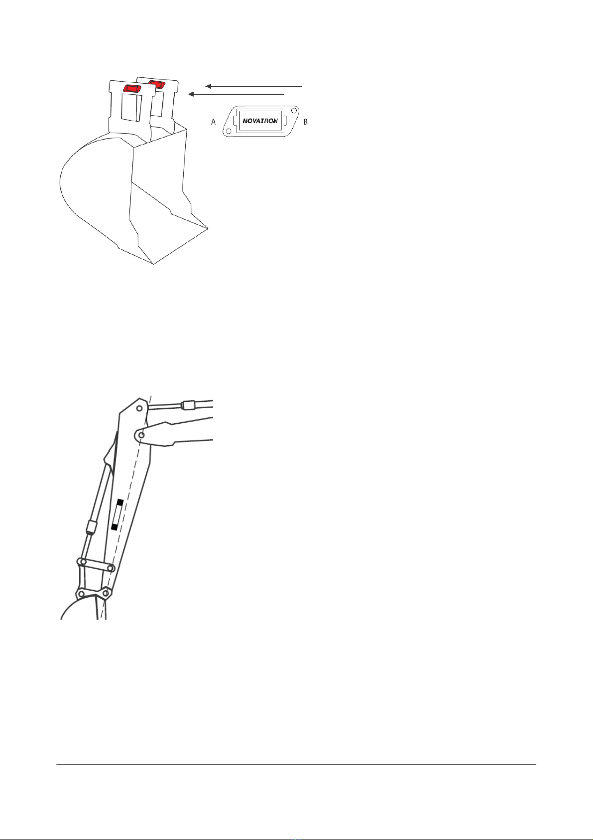
2.2.4 S ick, main boom, and ex ra boom sensors
Possible moun ing orien a ions for he s ick, main boom, and ex ra boom sensors are
•A1: lef side, measuremen axis A poin ing o he bucke (Figure 13)
•C1: righ side, measuremen axis A poin ing o he bucke
•C3: righ side, measuremen axis A poin ing o he cabin
If he boom consis s of wo par s he ex ra boom is he par ha is closer o he cabin.
Align he sensor wi h he boom line wi hin an accuracy of ±10°. The sensor should be moun ed in a
shel ered place if possible. To avoid harmful accelera ions, he sensor should be moun ed as close
o s ick/boom pin as possible.
I is no allowed o moun he main boom or ex ra boom sensor on he narrowing par of
he boom (Figure 14).
Check he movemen s of he cable af er ins alla ion.
XSITE EASY | Ins alla ion manual | Page 18 of 34
Figure 14. Main boom and ex ra boom sensor
Figure 13. S ick sensor (moun ing orien a ion A1)
This manual suits for next models
1
Table of contents
Other Novatron Control System manuals


Popular Control System manuals by other brands


Honeywell
Honeywell SILENT KNIGHT SK-Zone-6 Installation and maintenance instructions

Exhausto
Exhausto VEX320C installation guide

Itouchless
Itouchless IP01RSS user manual

CapstanAG
CapstanAG Synchro Operator's manual

IPAS
IPAS Axesso System System manual

Rieco-Titan Products
Rieco-Titan Products OSI-433N6 user manual