Novexx Solutions LA-SO User manual

Release 3 - 3/2016
OPERATING MANUAL
LA-SO
Applicator


Operating Manual LA-SO
03/2016 3Content
Content
Please Note -5
General Information -5
Validity of this manual and required compliance -5
How information is represented -6
For your safety -8
Intended use -8
Information and qualification -8
Safety functions -10
Operating safety of the machine -13
Every time before starting production -14
Warning symbols on the machine -15
Product description -16
Technical Data -16
Label material -16
Label rate -16
Application Process -17
Dimensions -18
Connections -18
Ambient conditions -18
Product Description -19
Product name -19
Intended Use -19
Configurations -19
System requirements -19
Functionality -20
Component overview -22
Startup -24
Assembly -24
Preparing the connection cable for the interlock circuit -24
Mounting on ALX 92x -25
Installing the service unit -26
Connecting the compressed air -27
Settings -28
Settings in parameter menu -28
Setting the choker valve -29
Setting the dwell time -29
Operation -30
Cleaning -30
Safety -30
Cleaning interval -30
Cleaning instructions -30

Operating Manual LA-SO
03/2016 | 00 5Please Note
Please Note
GENERAL INFORMATION
Validity of this manual and required compliance
Contents
The complete operating manual for the LA- SO consist of the following parts:
• User manual (for operating personnel)
• Operating manual (for operating and service personnel)
• Service manual (for service personnel)
• Spare parts catalogue (for service personnel)
This operating manual describes the installation and operation of the named applicators. For safe
and proper operation of the dispenser/print-dispenser with attached LA- SO, it is indispensable to
consult the operating manual for the relevant dispenser/print-dispenser too.
For technical questions not covered in this operating manual:
Follow the instructions of the service manual for the applicator or the dispenser/print-dispenser
or
Request a service technician from our sales partner.
Our sales partner's customer service department is available especially for configuration settings
and malfunctions.
Device designation
LA-SO is the abbreviation for "Label Applicator Swing-On". The abbreviation ‘SO’ (swing on) distin-
guishes this applicator from other application techniques such as ‘blow on’ or ‘tamp on’.
The LA- SO is available in different designs and versions. For details refer to chapter
Configurations on page 21.
Technical release
04/2013
Liability
NOVEXX Solutions reserves the right:
• to make changes in design, parts and software and to use equivalent parts instead of those
specified for the purpose of technological progress.
• to change information in this manual.
Any obligation to extend these changes to machines previously delivered is excluded.
Copyright
NOVEXX Solutions retains all rights to this manual and its appendices. Reproduction, reprint or any
other type of duplication, including parts of the manual, are permitted only with written approval.
Printed in Germany

Operating Manual LA-SO
03/2016 | 00 6Please Note
Manufacturer
NOVEXX Solutions GmbH
Ohmstrasse 3
D-85386 Eching, Germany
Tel.: +49-8165-925-0
Fax: +49-8165-925-231
www.novexx.com
How information is represented
Explanation of symbols
To enhance readability and make information easier to find, different types of information are iden-
tified:
Instruction with no order of tasks assigned
1. Numbered instructions introduced by preceding text
2. The specified order must be followed!
Special note for action that must be performed.
Explanation of an error cause in the reference of error messages.
• Enumeration of features
• Other feature
The Experts symbol identifies activities that are reserved exclusively for qualified and spe-
cially trained personnel.
The information symbol identifies notes and recommendations as well as additional infor-
mation.
Notes about hazards and risks
Important instructions that must absolutely be followed are specially highlighted:
Illustrations
Illustrations appear in the text where required. References to these illustrations are shown in [squa-
re brackets] containing the number of the illustrations. Uppercase letters after an illustration num-
ber, for example [12A], refer to the corresponding item within the illustration.
WARNING!
A warning symbol refers to risks that can result in severe or fatal injuries! The note contains safe-
ty measures to protect affected persons.
Instructions must be followed without exception.
CAUTION!
A caution symbol refers to risks that can result in property damage or personal injury
(minor injuries). The note contains instructions for preventing damage.
Instructions must be followed without exception.

Operating Manual LA-SO
03/2016 | 00 7Please Note
Key symbols
Keys in the dispenser control panel (if present) are represented as symbols.
If multiple keys must be pressed simultaneously, the symbols are joined in the text by "+": +
Keys in the printer control panel are represented as text, for example "Press the ONLINE key".
Parameters
Parameters in the parameter menu are represented in the format MENU NAME > Parameter name in
grey type.

Operating Manual LA-SO
03/2016 | 00 8Please Note
FOR YOUR SAFETY
Intended use
Although the applicator is „partly completed machinery“ under the terms of the machinery
directive, for reasons of clarity it is called „machine“ or „applicator“ in this manual
The LA -SO is a device for automatic application of self-adhesive labels that are supplied by
a print & dispense machine ALX 92x. The LA -SO is firmly attached to the ALX 92x.
The advantage of the LA -SO is that it can be used to apply labels to the fronts of products, which
is not possible using classic tamp-on applicators (e.g., LA -TO).
Furthermore, the LA -SO can also apply labels to the sides or tops of products moving at speeds
faster than 20 m/min.
Any other type of or more extensive application will be considered non-intended use. NOVEXX
Solutions shall assume no liability for damage resulting from non-intended use of the machine.
Information and qualification
Ensuring the necessary qualification
Only fully trained and authorised personnel are permitted to operate, adjust and maintain the
machine.
Service work must only be performed by qualified and appropriately trained technical specialists
(service technicians) or the customer service department.
Areas of responsibilities for operating and servicing the machine must be clearly defined and
consistently observed.
Personnel must also be regularly instructed in on-the-job safety and environmental protection.
Qualification for operation
The instruction provided for the operating personnel must ensure:
• that the operating personnel can use the machine independently and without danger.
• that the operating personnel can rectify minor operating faults (for example a paper jam) inde-
pendently.
At least 2 persons should be instructed in operation.
Have a sufficient quantity of label materials available for tests and instruction.
WARNING!
The device described here is „partly completed machinery“ as defined by machinery directive
2006/42/EC!
Do not set the applicator in operation until it has been determined that the machine in which
the applicator will be installed meets the requirements of directive
2006/42 EC, appendix IIA.

Operating Manual LA-SO
03/2016 | 00 9Please Note
Qualification for system integrators and service technicians
Knowledge required to install the device and perform service work must be demonstrated through
appropriate qualification. Only service personnel with technical training are able to assess the tasks
to be performed and recognise potential dangers.
• Knowledge acquired through technical training in mechanics and electronics (for example in
Germany the training to become a mechatronics engineer).
• Participation in a technical training course for the corresponding device offered by the manu-
facturer.
• The service personnel must be acquainted with the functionality of the device.
• The system integrator must be acquainted with the functionality of the system into which the
device is being integrated.
Making note of information
Any product liability and warranty claims will not be valid unless the machine is operated according
to the instructions in the operating manual.
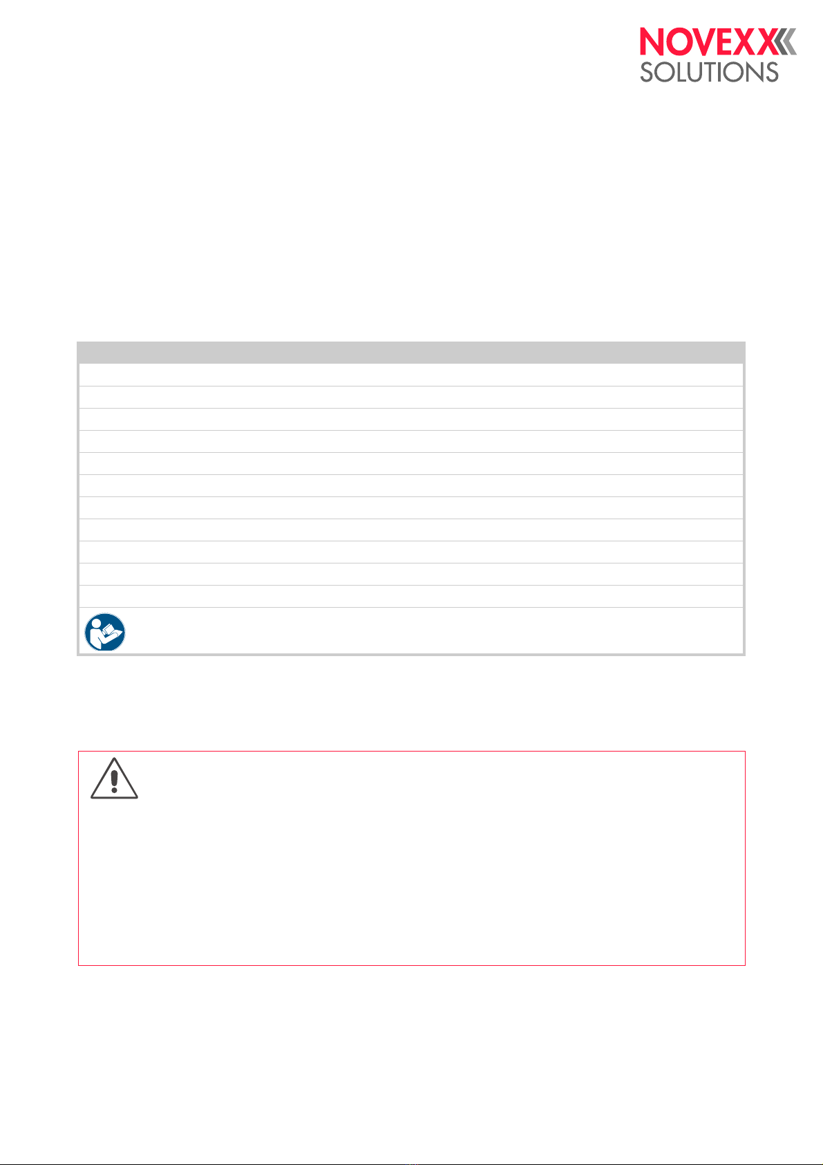
Tasks System integrator Operator Service technician
Install the machine X
Connect X
Make settings X
Switch on/off X X X
Insert/change material/ribbon X X X
Application-related settings X X X
Rectify minor operating faults a XX X
Clean the machine X X
Rectify major operating faults b X
Settings to the electronics/ mechanics X
Repairs X
Manual: Service manual Operating Manual Service manual,
spare parts catalogue
[Tab. 1] An example of the distribution of tasks among different qualified personnel.
a) For example faults during label feeding
b) For example replacement of lamp or printhead
WARNING!
The device can only be operated safely and efficiently by complying with all of the requisite in-
formation!
Carry out the installation, connection, programming, setting, and repairing of the machine ex-
clusively in accordance with the specifications in this manual.
Before beginning operation, read this operating manual and the operating manual of the dis-
penser/print-dispenser and follow all of the instructions.
Observe all additional safety and warning information given on the device.
Only technically knowledgeable persons are permitted to operate the device and make set-
tings on it.

Operating Manual LA-SO
03/2016 | 00 10 Please Note
Keep product information at hand
This user manual
must remain readily available for operating personnel at a location near to the machine.
must be kept in legible condition.
If the machine is sold, it must be made available to the new owner.
The safety and warning symbols and messages on the machine must be kept in a clean and
legible state. Replace any signs that are damaged or missing.
Safety functions
Protective equipment
A separating protective device must be installed by the system integrator in compliance with the
requirements of EN953. It could be a protective enclosure with a secured door, for example.
The separating protective equipment is not included in the scope of delivery of the machine.
WARNING!
Danger of personal injury and property damage!
Without operational safety functions and protective equipment the LA -SO may cause personal
injury and property damage.
Do not operate the machine without protective equipment.
Do not operate the machine when the safety functions are deactivated.

Operating Manual LA-SO
03/2016 | 00 11 Please Note
Connecting an interlocking guard
According to the EC machinery directive, the LA -SO is a partly completed machine. In order that
the completed machine matches the health and safety requirements of the machinery directive,
LA -SO must be safeguarded against access by an appropriate safeguarding device 1 [3].
Connect the interlock switch [3D] of the safeguarding device to the connector [2] delivered with
the applicator [3E].
Plug the connector to the switch box [1B].
Operation of the LA -SO without the described safeguarding device shall be regarded as abnor-
mal use. NOVEXX Solutions assumes no liability for damage due to abnormal use of the printer.
[1] Connecting the interlock switch (A) of the safeguarding device (or an emergency-stop switch) to a LA -SO.
[2] Plug that comes with the LA -SO for
connecting an interlock switch
(article number: A102076).
1) Movable interlocking guard according to EN ISO 12100-1, 3.25.4
A
B
7

Operating Manual LA-SO
03/2016 | 00 13 Please Note
Emergency Stop
An external Emergency Stop device must be installed by the system integrator. It could be an Emer-
gency Stop button located outside of the protective equipment, for example. The button must be
pressed if a hazardous situation occurs or in the event of an emergency.
The external Emergency Stop device is not included in the scope of delivery of the machine.
Checking the safety functions
The following safety functions can be checked by the user or a service technician:
Operating safety of the machine
Intended use
The machine must only be used in accordance with the specifications in section Intended use
on page 8.
Warning of injuries due to electrical shock
Safety function Functional check
Emergency Stop
Activate the Emergency Stop device (for example press the
Emergency Stop button).
The applicator must stop immediately.
Protective
equipment
Interrupt the safety switch circuit (for example open the
safety door).
The applicator must stop immediately.
Switching-on valve
Switch on compressed air.
The applicator foot moves from the end position slowly up to
the home position. If the movement occurs abruptly, the swit-
ching-on valve must be adjusted by a service technician.
[Tab. 2] Overview: Checking the safety functions
WARNING!
The machine to which the applicator is attached works with mains voltage! Contacting electrically
live components can cause lethal electrical shocks and burns.
Switch the machine off before cleaning and servicing.
Keep the machine dry.
If a liquid gets into the machine, switch off the machine immediately. Notify a service techni-
cian.
The applicator must only be connected with other machines if they meet the requirements of
a SELV circuit (Safety Extra-Low Voltage circuit) in accordance with EN 60950.
In case of emergency switch off the machine.

Operating Manual LA-SO
03/2016 | 00 14 Please Note
Warning of injury hazards from mechanical components
Every time before starting production
Check the safety functions to ensure they are working properly (see Checking the safety functi-
ons on page 13).
Check the machine for visible damage. Report defects that are discovered immediately.
Use personal protective equipment properly, for example wearing a hair net.
Remove material and objects that are not required from the working area of the machine.
Ensure that only authorised persons remain in the working area of the machine.
Ensure that no one can be endangered by the machine starting up.
WARNING!
Danger of crushing between the machine and conveyor equipment and between movable parts
of the applicator!
The machine may only be operated with higher-level protective equipment.
Never remove or bypass the protective equipment that is designed to prevent reaching in whi-
le the machine is in operation.
Danger of injury due to moving and rapidly rotating parts!
Maintain a safety clearance from the machine when it is in operation.
Never reach into a machine that is running.
Switch off the machine before making any mechanical adjustments.
Keep clear of the area around moving parts even when the machine is stopped if there is any
possibility of the machine starting up.
Entanglement hazard!
When working in the vicinity of machines in operation, do not wear ties, loose clothing items,
jewellery, wrist watches or similar objects on your body.
Long hair must be kept in a hair net and must not be worn loose.
Tripping hazard!
Lay the connection cable and pneumatic hoses (if fitted) so that no one can trip over them.

Operating Manual LA-SO
03/2016 | 00 15 Please Note
Warning symbols on the machine
[4] Warning note on the LA-SO.
Meaning of the warning symbols:
CAUTION!
Warning symbols on the machine provide important information for the operating
personnel.
Do not remove warning symbols.
Replace missing or illegible warning symbols.
Warning symbol Meaning Order No.
The warning symbol "Danger of crushing"
warns of dangerous movements of the de-
vice that could lead to crushing. Switch off
the device previously.
A103530
[Tab. 3] Meaning of the warning symbols
A

Operating Manual LA-SO
03/2016 | 00 16 Product description
Product description
TECHNICAL DATA
Label material
Label rate
Example:
With the application shown afterwards (Tab. 4) [5], a rate of 18 labels/min is possible.
If one of the settings is changed, all other settings must be fit, what may also change the label
rate.
Type Self-adhesive (paper, plastic materials) a
a) As a result of static charge and friction effects, plastic materials may tend to crease during the dispen-
sation step. Therefore, plastic materials must be tested under application conditions before being
used in production.
Material width 80-150 mm
Material length 80-210 mm
Label on front max. 20 labels/min a
a) Depends on: pressure speed, pressure rate, product distance, product speed, label size and label ma-
terial.
Label on top/side max. 30 labels/min a
Setting Value
Distance LA-SO centre - Product 145 mm
Label length 152.4 mm
Apply time tAppl 500 ms
Product length 400 mm
Product distance min. 230 mm
Print speed 200 mm/s
Product speed 15 m/min
[Tab. 4] Settings for example application.

Operating Manual LA-SO
03/2016 | 00 17 Product description
[5] LA-SO example application (schematic).
Application Process
[6] Application distance. Left: label on side. Right: label on front.
Application distance a
a) Distance between pressure dispensing system and label.
Label on front [6B]: approx. 10 cm b
Label on top/front [6A]: approx. 20 cm
b) When labels are used that are smaller than the pressure plate, the exposed area of the pads can be
added to the application distance.
Application direction
Side labelling: label on front or side,
see chapter Side labelling on page 21.
Top labelling: label on front or top,
see chapter Front labelling on page 21.
Tolerance of label position ±2mm
Product speed during appli-
cation
Label on front: max. 15 m/min
Label on side/top: max. 30 m/min
Air stream Blowers
100 mm
45 mm
Product length
Label Size
Printspeed
t
Dwell
Product
speed
Product distance
A
B

Operating Manual LA-SO
03/2016 | 00 18 Product description
Dimensions
Connections
Ambient conditions
W x H x D 240 x 355 x 500 mm
Weight 6.5 kg
Power supply Via applicator interface
Power consumption 15 VA
Supply air pressure 4-6 bar
Air consumption approx. 0.3 l/stroke
Operating temperature 5-40°C
Storage temperature 0-70°C
Air humidity 45-75% non-condensing
Noise emissions < 70 dB(A)
Protection rating IP 21

Operating Manual LA-SO
03/2016 | 00 19 Product description
PRODUCT DESCRIPTION
Product name
LA-SO is the abbreviation for "Label Applicator Swing-On". The abbreviation ‘SO’ (swing on) dis-
tinguishes this applicator from other application techniques such as ‘blow on’ or ‘tamp on’.
Intended Use
The advantage of the LA-SO is that it can be used to apply labels to the fronts [7C] of products,
which is not possible using classic tamp-on applicators (e.g., LA-TO).
Furthermore, the LA-SO can also apply labels to the sides or tops of products moving at speeds
faster than 20 m/min.
Configurations
The LA-SO is available in both right-handed and left-handed versions. LA-SO and ALX 92x must
be of the same handedness, that is both must be RH or LH versions.
System requirements
Compressed air
• Compressed air connection must be available
• Mounting surface for pressure controller: See Installing the pressure regulator on page 15
ALX 92x
• ALX 92x with standard dispensing edge and firmware version 5.33 or higher.
• Installed applicator interface (optional) with firmware version 1.23 or higher. If the applicator in-
terface was retrofittet, pay attention that the D-Sub 15 connector for Avery applicators (top side
of the front hood) is available.
Displaying printer firmware version: SERVICE DATA > MODULE FW VERS. > System Version
Displaying firmware version of applicator interface: SERVICE DATA > MODULE FW VERS. > Applicator
Int.

Operating Manual LA-SO
03/2016 | 00 20 Product description
Functionality
The LA-SO is a supplementary module for mounting at an ALX 92x. It takes over labels from the
dispensing edge of the ALX 92x and moves them in a curved movement to the product, where it
presses the labels on (frontside) or rolles it on (side, top side).
The advantage of the LA-SO is that it can apply labels to the front side of a product, which is not
possible with classic tamp-on applicators (e.g. LA-TO).
Furthermore, the LA-SO can label products that are moving with more than 20 m/min on the side
or top side.
[7] Designations for the sides of the product. Possible label positions for side labelling (left figure) and top
labelling (right figure).
ASide
BTop
CFront
Initially, the LA-SO is in idle mode and the swivel arm is folded inwards.
As soon as a start signal is received from the product sensor, the ALX 92x prints and dispenses a
label [8B]. The stream of compressed air emitted from the support air nozzle [8A] presses the label
against the pressure plate of the LA-SO [8C]. The label is held in place there by a vacuum created
by the fan on the swivel arm.
[8] Dispensing labels onto the pressure plate.
Once a label has been dispensed, a compressed air valve switches and causes the swivel arm to
move. The swivel movement ends once the time limit set in the ALS 92x menu elapses. This time
limit must be set so that the swivel arm reaches the product before the reverse movement begins.
ABC
AC
B
Other manuals for LA-SO
1
Table of contents
Other Novexx Solutions Industrial Equipment manuals