ABB Terra DC wallbox User manual

—
MANUAL: NORTH AMERICA
Terra DC Wallbox
Installation Manual

Notice
This document contains information about one or more ABB products and may include a description of
or a reference to one or more standards that may be generally relevant to the ABB products. The
presence of any such description of a standard or reference to a standard is not a representation that all
of the ABB products referenced in this document support all of the features of the described or
referenced standard. In order to determine the specific features supported by a particular ABB product,
the reader should consult the product specifications for the particular ABB product.
ABB may have one or more patents or pending patent applications protecting the intellectual property in
the ABB products described in this document.
The information in this document is subject to change without notice and should not be construed as a
commitment by ABB. ABB assumes no responsibility for any errors that may appear in this document.
In no event shall ABB be liable for direct, indirect, special, incidental or consequential damages of any
nature or kind arising from the use of this document, nor shall ABB be liable for incidental or
consequential damages arising from use of any software or hardware described in this document.
This document and parts thereof must not be reproduced or copied without written permission
from ABB, and the contents thereof must not be imparted to a third party nor used for any unau-
thorized purpose.
Copyrights
All rights to copyrights, registered trademarks, and trademarks reside with their respective owners.
Copyright © 2020 ABB.
All rights reserved.

Contents
1Introduction .....................................................................................................................................................6
1.1 Preface...................................................................................................................................................6
1.2 Intended document users.......................................................................................................................6
1.3 Terra DC Wallbox hardware ordering details............................................................................................6
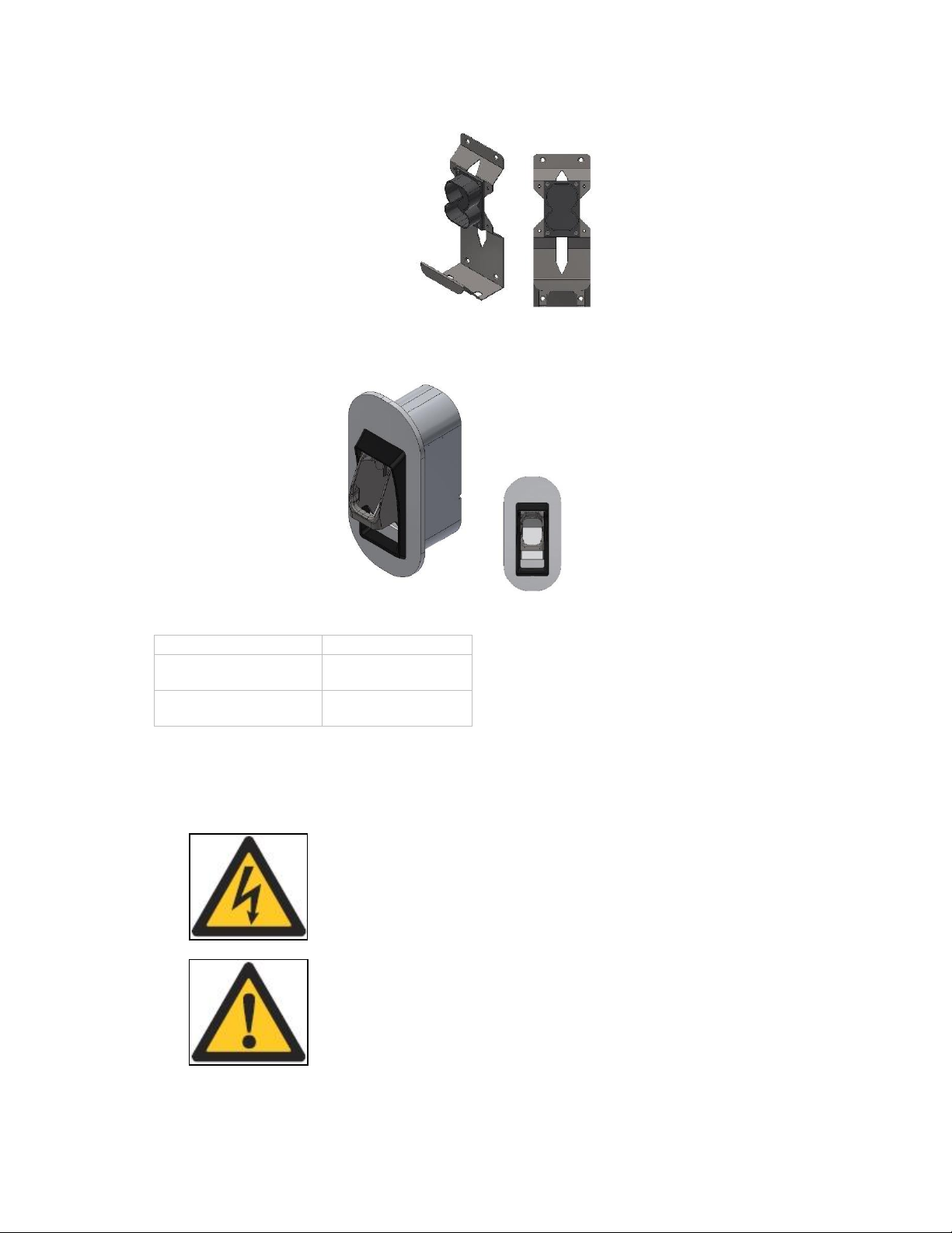
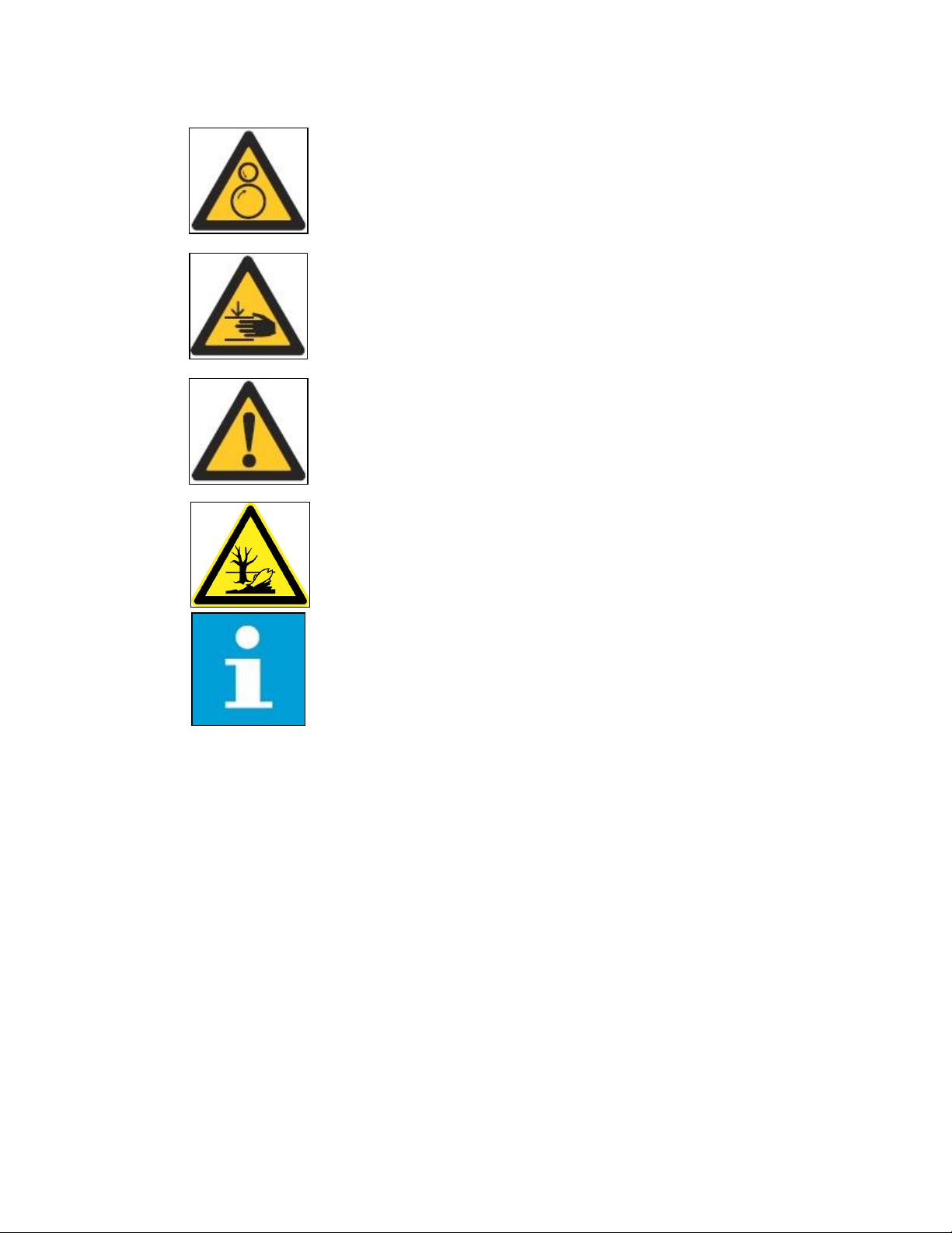
1.4 Signs ......................................................................................................................................................7
1.4.1 Owner responsibilities............................................................................................................8
1.4.2 Tilting and handling................................................................................................................9
1.4.3 Sharp edges ...........................................................................................................................9
1.4.4 Electric hazards......................................................................................................................9
1.4.5 Installation safety.................................................................................................................10
1.5 Environment and disposal of waste.......................................................................................................10
2Description of the product.............................................................................................................................. 11
2.1 Overview of the system........................................................................................................................ 11
2.1.1 Complete overview.............................................................................................................. 11
2.1.2 External view ....................................................................................................................... 12
2.1.3 Inside view........................................................................................................................... 13
3Installation Planning and Design.....................................................................................................................14
3.1 Internet connection..............................................................................................................................14
3.1.1 Internet via cellular connection ............................................................................................14
3.1.2 Internet via ethernet connection..........................................................................................14
3.2 Electrical requirements......................................................................................................................... 15
3.2.1 Required electrical grid configuration ................................................................................... 15
3.2.2 Overcurrent protection device.............................................................................................. 17
3.2.3 Conduit for power input wires.............................................................................................. 17
3.2.4 Specification for power input wires ...................................................................................... 17
3.2.5 Conduit for ethernet cable ...................................................................................................18
3.2.6 Specification for ethernet cable............................................................................................18
3.3 DC Wallbox placement .........................................................................................................................18
3.3.1 Charging cable reach............................................................................................................18
3.3.2 DC Wallbox position with respect to parking space ............................................................... 19
3.3.3 Required space for installing and maintaining the DC Wallbox...............................................20
3.3.4 Ventilation and airflow required for the DC Wallbox ............................................................. 21
3.3.5 Considerations for where to position DC Wallbox vertically................................................... 21
4Installation instructions..................................................................................................................................23
4.1 About construction...............................................................................................................................23
4.2 Instruction for a wall bearing................................................................................................................23
4.2.1 Mounting on a pedestal .......................................................................................................23
4.3 Power feed...........................................................................................................................................23
4.4 Internet connection..............................................................................................................................23

5Receiving, Placing and connecting................................................................................................................. 24
5.1 Receiving the Wallbox ..........................................................................................................................24
5.2 Unpacking the charging and mounting preparations .............................................................................25
5.2.1 Unpacking............................................................................................................................25
5.2.2 Mounting preparations ........................................................................................................26
5.3 Move cabinet to position......................................................................................................................26
5.3.1 Options................................................................................................................................26
5.4 Mounting the Terra DC Wallbox............................................................................................................26
5.4.1 Mounting the Terra DC Wallbox............................................................................................27
5.4.2 Install cable gland(s) or connect conduit to the unit.............................................................. 31
5.5 Connect cables.....................................................................................................................................33
5.5.1 Connect PE of power cable...................................................................................................33
5.5.2 Connect power cable............................................................................................................34
6Commissioning...............................................................................................................................................36
6.1 Commissioning preparation..................................................................................................................36
7Maintenance and Cleaning of the cabinet ......................................................................................................37
7.1 Recommended Periodic maintenance...................................................................................................37
7.2 Cleaning of the cabinet.........................................................................................................................37
8Technical Data ................................................................................................................................................38
8.1 Electrical data.......................................................................................................................................38
8.2 Mechanical data...................................................................................................................................39
8.3 Environment ........................................................................................................................................39
8.4 Certifications........................................................................................................................................39
9Contact information ...................................................................................................................................... 40
10 Appendix A – Mounting points.......................................................................................................................41
10.1 Terra DC Wallbox Charger wall mounting ..............................................................................................41
11 Appendix B - Disposal instruction.................................................................................................................. 42
11.1 Directive on Waste Electrical and Electronic Equipment (WEEE – 2012/19/EU)......................................42
12 Appendix C – Pedestal requirements............................................................................................................. 43

Glossary
AC
Alternating Current.
CCS
Combined Charging System. This is the name of the
charging protocol of European and North American car
makers.
CHAdeMO
DC fast charging method for electric vehicles.
Contractor
Entity hired by the owner / site operator to do
engineering, civil and electrical installation work.
DC
Direct Current.
EV
Electric Vehicle.
Grid provider
Company responsible for the transportation and
distribution of electricity.
HMI
Human Machine Interface; the display/screen on the
charger.
NOC
ABB Network Operating Centre; remotely checks the
correct functioning of the charger.
Owner
The legal owner of the charger.
OCPP
Open Charge Point Protocol. Open standard for
communication with charge stations.
PE
Protective Earth.
PPE
Personal Protective Equipment.
Equipment such as safety shoes, helmet, glasses,
gloves.
RCD
Residual Current Device. Breaks the connection if a
residual current is detected.
RFID
Radio-Frequency IDentification. RFID is a
communication technology by means of radio waves to
transfer data over a very short distance between a
reader and an electronic tag or card.
Site operator
This entity is responsible for the day to day control of
the charger. The site operator can be the owner, but not
necessarily.
User
The owner of an electric vehicle, who uses the Charge
Station to charge that vehicle.

2020-08-06 6/44
1Introduction
1.1 Preface
This guide provides an overview for the installation of the Terra DC Wallbox.
The Terra DC Wallbox charging station is an easy to install DC fast charger for electric vehicles. Fast chargers are
electrical installations with high electric currents. Therefore, the installation must be planned carefully, and must be
done by certified personnel only (according to local standards). Local regulations shall take precedence if they list
different installation requirements than prescribed in this Installation Manual.
The Terra DC Wallbox is offered in a variety of configurations and with multiple connector types. The different versions
are described in section 1.3.
Before installing the Terra DC Wallbox, read this installation guide carefully and attentively. Be sure to follow all
instructions when installing the charger. ABB is not responsible for any damage caused by not following or incorrectly
executing the instructions described in this manual.
1.2 Intended document users
This document is intended to be used by:
•Customers who have purchased a Terra DC Wallbox or customers in the process of ordering and require
additional details on installation.
•Contractors who are responsible for site preparation and/or installation of a Terra DC Wallbox.
1.3 Terra DC Wallbox hardware ordering details
ABB’s Terra DC Wallbox is offered in the following configurations.
Version
1-Phase
3-Phase
Terra DC Wallbox C UL
X
X
Terra DC Wallbox J UL
X
Terra DC Wallbox CJ UL
X
X
CCCS-1 (Combo) standard
JCHAdeMO standard
CJ CCS-1 (Combo) standard and CHAdeMO standard
All variations are offered with charging cable lengths of 7 meters (23 ft). The Terra DC Wallbox comes with the
standard connector holsters as shown.

TERRA DC WA LLBOX
2020-12 7/44
Optional connector holsters shown below may be purchased separately with the order code details shown below.
Charging cable type
ABB order code
CCS-1
ABB6AGC076604
CHAdeMO
ABB6AGC076601
1.4 Signs
The following signs are used on the equipment and in this manual:
DANGER
Hazardous voltage
Identifies a hazard that could result in severe injury or death through
electrocution.
WARNING
Various
Identifies a hazard that could result in severe injury or death.

TERRA DC WA LLBOX
2020-12 8/44
WARNING
Rotating parts
Identifies a hazard that could result in injury due to the presence of
rotating or moving parts.
WARNING
Pinch Hazard
Identifies a hazard that could result in injuries, in which some body parts
are pinched or crushed.
CAUTION
Various
Identifies a hazard that could result in damage to the machine, other
equipment, and/or environmental pollution.
CAUTION
Environmental damage
Identifies a hazard that could result in environmental damage and/or
environmental pollution.
NOTICE
Contains remarks, suggestions or advice.
1.4.1 Owner responsibilities
The owner and site operator are required to:
•Operate the charge station with the protective devices installed and to ensure all protective devices are
correctly installed after carrying out installation or maintenance work.
•Write an emergency plan that instructs people what to do in case of emergency.
•Prepare the site where the charge station will be installed according to the requirements described in this
guide.
•Ensure there is sufficient space around the charger to carry out maintenance work.
•Appoint a person responsible for the safe operation of the charge station and for the coordination of all work.
The owner is cautioned that changes or modifications not expressly approved by ABB could void the owner’s authority
to operate the equipment and ABB’s warranty policy.
Neither ABB nor its affiliates shall be liable to the purchaser of this product or third parties for damages, losses, costs
or expenses incurred by purchaser or third parties as a result of: an accident, misuse or abuse of this product or
unauthorized modifications, repairs or alterations to this product, or failure to strictly comply with ABB’s operating and
maintenance instructions.

TERRA DC WA LLBOX
2020-12 9/44
1.4.2 Tilting and handling
WARNING
Heavy equipment
The Terra DC Wallbox weighs approximately 70 kg. Follow the handling
Instructions:
1. Two people are recommended for the installation and wall-mounting of
a Terra DC Wallbox.
2. Do not drop the Terra DC Wallbox.
1.4.3 Sharp edges
WARNING
Sharp metal edges
There could be sharp metal edges inside the Terra DC Wallbox. It is
recommended to wear mash protecting gloves when working inside the
charger.
1.4.4 Electric hazards
DANGER
Hazardous voltage
The Terra DC Wallbox contains conductors under hazardous electrical
voltages. The grid terminals on the internal DIN rail may carry hazardous
voltages, even if all circuit breakers are switched off.

TERRA DC WA LLBOX
2020-12 10/44
1.4.5 Installation safety
DANGER
Hazardous voltage
Instructions:
1. Always switch off the input circuit feeding the unit, (external disconnect
or breaker) before performing any installation, disassembly, repair or
replacement of components. Follow appropriate requirements for safe
work practices, including but not limited to NFPA-70e.
2. Perform a voltage check to ensure electrical power is disconnected
from the system.
3. Only ABB certified technicians should commission the Terra DC Wallbox.
4. When the system is in an open or dangerous condition, do not allow
unqualified persons to go near it. Instruct and warn people about the
potentially harmful high voltages.
5. The installation and maintenance personnel must supply their own
lighting equipment because the Terra DC Wallbox has no lights inside the
cabinet.
6. Always connect the Protective Earth (PE) first, before connecting the
other power input wires.
7. Be sure to properly and securely reassemble the Terra DC Wallbox’s
enclosure after installation or service operations.
8. When handling the equipment, a proper lifting device should be used in
accordance with your local EHS policies.
1.5 Environment and disposal of waste
NOTICE
Always follow the local rules and regulations regarding disposal of any
(non-reusable) Terra DC Wallbox parts.

TERRA DC WA LLBOX
2020-12 11/44
2Description of the product
2.1 Overview of the system
2.1.1 Complete overview
Example of a complete installation
A Power distribution board of the owner
B Cables in conduit
C Terra DC Wallbox
D Parking space for charging
E Electric vehicle

TERRA DC WA LLBOX
2020-12 12/44
2.1.2 External view
A Display / HMI EEmergency stop button
B RFID card reader FAC input connection point for Conduit
C DC Charging cable GAir inlet
DAir outlet HStandard Holster (included)
IOptional Holster (purchased separately)
Standard charging cable
holster supplied with DC
wallbox
Optional charging cable
holster sold separate
from DC wallbox

TERRA DC WA LLBOX
2020-12 13/44
2.1.3 Inside view
A AC input board D Cable gland for DC output(2x)
B CPI and IMI boards E Cable gland for AC input
C External Fan (2x)

TERRA DC WA LLBOX
2020-12 14/44
3Installation Planning and Design
This section provides several considerations for the DC Wallbox installation planning and design, which are to be
made by the customer to ensure a successful project.
3.1 Internet connection
ABB requires an internet connection to the DC Wallbox to conduct remote service operations including, over-
sight of the product during the warranty period, diagnosis and troubleshooting of issues, and performing soft-
ware firmware update. Not having internet connection to the DC Wallbox may severely impact, or even void, the
product warranty and/or ABB’s service level agreement (SLA).
It is the installer’s responsibility to ensure reliable internet connection to the DC Wallbox is made. Contingency
planning and the associated costs are the responsibility of the installer.
3.1.1 Internet via cellular connection
The preferred method of establishing internet connection to the charger is using the charger’s standard featured
hardware with ABB’s Charger Connect service offering, which provides internet access via Vodafone’s 4G LTE
wireless network.
In the USA, Vodafone primarily roams on the AT&T and T-Mobile 4G LTE networks. It is expected that a cellular
availability test is performed prior to construction to ensure there is reasonable signal quality to at least one of
the AT&T and T-Mobile 4G LTE bands 2 (1900 MHz), 4 (1700/2100MHz), or 12 (700 MHz).
The signal strength must be greater than -85dbm and should be measured with a cellular network signal meter,
such as a Squid-4G or Sure Call device. Handheld mobile phones are not recommended for assessing signal
strength since they are not reliable measuring devices.
The DC Wallbox only supports SIM cards provided by ABB. Customer procured SIM cards are not supported.
3.1.2 Internet via ethernet connection
Internet connection to the charger may be performed by connecting an ethernet cable to the charger from other
on-site IT infrastructure. However, due to the scope of work required for integrating this solution to ensure se-
cure communication, this method is typically not preferred.
ABB may require additional commissioning fees if ethernet cable method for establishing internet is used, de-
pending on the situation. Please contact your ABB sales representative for more details.
See sections 3.2.5 and 3.2.6 for more details on connection of conduit carrying ethernet cable and specification
of the ethernet cable.

TERRA DC WA LLBOX
2020-12 15/44
3.2 Electrical requirements
CAUTION
The installation company is responsible to design and install the electrical
installation according to the local regulations.
3.2.1 Required electrical grid configuration
The DC Wallbox may be ordered with either a 1-phase or 3-phase input variant. It is essential that the DC Wall-
box is installed in the proper electrical grid configuration. The allowable grid configurations are shown in the
three figures below. Please observe the 3-phase variant DC Wallbox supports only one grid configuration and
the 1-phase variant DC Wallbox supports two different grid configurations. For the 1-phase variant DC Wallbox,
ABB recommends the electrical designer to consider power distribution phase balancing design requirements.
Electrical grid configuration required for 3-phase, DC Wallbox UL variant (3ø, 480Y/277V input)
3-phase
480Y/277V
Terra DC
Wallbox
Neutral
Grounding
Electrode
Conductor
277V
480V
Line 1
Line 2
Line 3
Neutral
Ground
Line 1
Line 2
Line 3
40A fused
switch or
circuit breaker

TERRA DC WA LLBOX
2020-12 16/44
One of two electrical grid configurations acceptable for use with 1-phase, DC Wallbox UL vari-
ant (1ø, 208V input)
Neutral
Grounding
Electrode
Conductor
120V
240V 1-phase
240V
Terra DC
Wallbox
Line 1
Line 2
Ground
Line 1
Line 2
125A fused
switch or circuit
breaker
One of two electrical grid configurations acceptable for use with 1-phase, DC Wallbox UL vari-
ant (1ø, 240V input)
1-phase
208V
Terra DC
Wallbox
Neutral
Grounding
Electrode
Conductor
120V
208V
Line 1
Line 2
Ground
Line 1
Line 2
Line 3
125A fused
switch or circuit
breaker
208V

TERRA DC WA LLBOX
2020-12 17/44
NOTICE:
The grid connections shown for the various configurations of the DC Wallbox are mandatory.
Failure to adhere to these instructions may partially or fully void the product warranty, result
in a costly site visit to reconfigure the grid configuration, and/or cause several site visits for
the DC Wallbox commissioning. ABB is not responsible for scheduling delays and additional
costs from not properly planning the installation. If ABB is contracted to perform the DC
Wallbox commissioning, ABB observes the right to charge additional money for more than
one site visit required for the commissioning due to an initial, improper installation of the DC
Wallbox.
Important steps to ensure project success include:
1. Identify the grid configuration at the location where the DC Wallbox will be installed. If
the grid configuration available is not okay for use with the DC Wallbox, then determine
how to establish the required grid connection. A transformer solution offered by ABB is
available to derive the required grid configuration when the required grid configuration is
not available. Contact your local ABB sales representative for more details.
2. Select the 1-phase or 3-phase variant of the DC Wallbox according to Section 1.3 titled
Terra DC Wallbox hardware ordering details based on Step 1 above.
3. Carefully execute a project plan to ensure the correct variant of DC Wallbox is used on
the project and that the project site’s grid configuration is compatible with the DC Wall-
box.
4. Verify the actual grid configuration the DC Wallbox is installed in matches the described
criteria during the DC Wallbox commissioning.
3.2.2 Overcurrent protection device
Each variant of the DC Wallbox is recommended to be fed by the circuit breaker or fuse ratings shown below.
•1-phase, 208-240V DC Wallbox variant: 2-pole, 125A circuit breaker or fuses
•3-phase, 480Y/277V DC Wallbox variant: 3-pole, 40A circuit breaker or fuses
3.2.3 Conduit for power input wires
Each variant of the DC Wallbox supports up to a 1-1/4” trade size conduit connection.
3.2.4 Specification for power input wires
The exact size and type of wires used must be defined by the customer and be protected by customer provided
overcurrent protection according to local codes and regulations.
The input terminals for both 1-phase and 3-phase UL variants of the DC Wallbox accept a range of wire sizes
from 10 AWG to 0 AWG. Wire terminals are rated 75C.
The 3-phase UL variant DC Wallbox requires Three (3) phase wires, One (1) neutral wire, and One (1) wire for
protective earth. (3W+N+G)
The 1-phase UL variant DC Wallbox requires Two (2) phase wires and One (1) wire for protective earth. (2W+G)

TERRA DC WA LLBOX
2020-12 18/44
All wires for 3-phase and 1-phase variants of the DC Wallbox may connect directly to the ABB provided termi-
nals, with exception to the protective earth wire for the 3-phase variant DC Wallbox. The protective earth wire
for the 3-phase variant DC Wallbox requires for the installer to crimp a terminal onto it using the terminal manu-
facturer’s recommended crimp procedure and tool.
The integrity of the electrical grounding is essential. Ensure that the equipment grounding terminal is used in
the device and an actual grounding conductor is installed to provide a path back to the source upstream panel.
(Do not use the conduit or raceway as the sole equipment grounding conductor).
3.2.5 Conduit for ethernet cable
The DC Wallbox does not have a hole designated for a conduit carrying only an ethernet cable to connect to. If
ethernet cable solution is required for an installation, please contact your ABB sales contact person to review
ethernet cable entry solutions.
3.2.6 Specification for ethernet cable
If the cellular connection is not available, ethernet connection must be made to the charger using a shielded
8P+PE ethernet cable with RJ45 connectors. Additional recommendations include:
•Maintain distance of 75 meters or less. Distances over 75 meters require a custom engineered solution.
•Minimum bandwidth:
upload: 128 kb/s
download: 4 Mb/s
•99.9% availability
•600V rated cable that may route beside input power wires for short distances
3.3 DC Wallbox placement
Placement of the Terra DC Wallbox must be carefully determined by accounting for charging cable reach, DC
Wallbox position with respect to parking space, bollards and wheel stops, ventilation and working clearances,
and other local codes and regulations (e.g. ADA requirements in the USA).
3.3.1 Charging cable reach
The Terra DC Wallbox charging cables are available in lengths of 3.5 or 7 meters. The charging cables exit the
charger enclosure on both the right and left sides. The cables and the connectors mounted on the cables are dif-
ferent depending on the charging standard and vary in flexibility.
The figure below shows an example of a dual connector charger with both types of connector and the corre-
sponding reach area. The green circle with a continuous line describes the CHAdeMO cable 3.5m and the red
circle with a continuous line describes the CCS cable 3.5m. The broken lines indicate the same cable types with a
length of 7 meters (23 ft).

TERRA DC WA LLBOX
2020-12 19/44
3.3.2 DC Wallbox position with respect to parking space
The charging inlets on a vehicle can be located at different positions depending on the manufacturer. The most
common vehicles have inlets located either on the front or in the back on either the left or right side.
This makes some charger placements with respect to the parking space more favorable than others. Keep this in
mind when designing a site. Below are examples of possible situations:

TERRA DC WA LLBOX
2020-12 20/44
3.3.3 Required space for installing and maintaining the DC Wallbox
The Terra DC Wallbox requires a minimum space of 36” x 48”. This space is calculated as follows:
- Charger size (H x W x D): 30.3 x 23 x 11.8 in
- Bottom side 23.6” (15.75” from the Terra DC Wallbox in order to avoid obstacles for the electrical connection).
- Left and right side 300mm/12”, in order to operate without obstacles on the lateral side of the Terra DC Wall-
box.
Note: The below dimensions are shown in millimeters.
Other manuals for Terra DC wallbox
4
Table of contents
Other ABB Industrial Equipment manuals
Popular Industrial Equipment manuals by other brands

Axon
Axon EZ-Seal Operator's manual

Norgren
Norgren VR10 Operation & service manual

Siemens
Siemens SIMATIC NET FastConnect RJ45 Plug 90 Assembly instructions

Olympus
Olympus IPLEX GAir IV9000GA instructions

Zimmer
Zimmer HRC-03-117137 Installation and operating instructions

Advantage Controls
Advantage Controls MegatronXS Quick steps