manuals.online logo
Brands
  1. Home
  2. •
  3. Brands
  4. •
  5. novotechnik
  6. •
  7. Accessories
  8. •
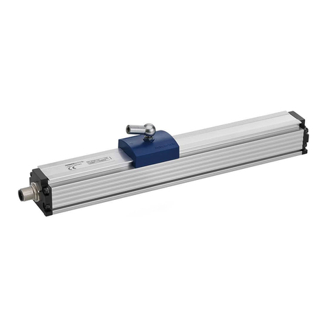
  9. novotechnik TEX series User manual

novotechnik TEX series User manual

TEX Gebrauchsanleitung
TEX Instructions for Use
Artikelnummer: 517142 / 05 Änderungen vorbehalten / Specifications subject ot change 2009/07
1 Sicherheitshinweise
1.1 Installation und Inbetriebnahme
Der Wegaufnehmer ist nur von Fachpersonal und unter
Berücksichtigung aller geltenden Sicherheitsbestimmungen in
Betrieb zu nehmen.
Bei unbefugten Eingriffen, unzulässiger Anwendung oder
Nichtbeachtung der Montagehinweise kommt es zum Verlust von
Garantie- und Haftungsansprüchen.
Alle Maßnahmen zum Schutz von Personen bei einem Defekt des
Wegaufnehmers müssen vor der Inbetriebnahme getroffen
werden.
Schubstange nicht einfetten!
Durch starke Temperaturschwankungen (Kondensation),
kann sich Feuchtigkeit im Wegaufnehmer bilden, und die
Funktion des Wegaufnehmers beeinträchtigen.
1.2 Elektrische Anschlüsse
Die Versorgungsspannung darf nur ausschließlich an die dafür
vorgesehenen Anschlüsse verbunden werden. Die Abschirmung
des Anschlusskabels ist an Masse anzuschließen. Falsche
Verbindungen und Überspannung können zur Beschädigung der
Bauteile führen. Prüfen Sie deshalb vor dem Einschalten die
Anschlüsse immer sorgfältig.
2 Einbau
1 Safety notes
1.1 Installation and startup
The linear transducer must be installed by qualified personnel
in consideration of all relevant safety regulations.
In case of unauthorized modifications, non-permitted usage or
non-observance of installation instructions, the warranty and
liability claims will be lost.
All personal protection measures in case of a transducer defect
or failure must be taken before startup.
Do not lubricate the actuating rod!
Strong temperature variations (condensation) can
deposit humidity in the position transducer and impair the
function of the linear transducer.
1.2 Electrical connections
The supply voltage is to be applied only at the terminals
provided. Cable shielding is to be connected to ground level.
Improper connections and overvoltage can damage the
components. Please always check the connections carefully
before turning on the system.
2 Installation
2.1 Anschlussschema / Terminal diagram
1
34
4
1
3U
max
42V
I
max
<
1µA
2.2 Steckerbelegung / Pin configuration
3
4
1
Lastfreier Spannungsteiler!
Voltage divider free of load!
Konfektionierte Kabel können abweichende
Farbbelegung aufweisen.
Bei Verlängerung des Kabels ist auf ausreichende
Schirmdämpfung zu achten.
Dargestellte Belegung für ausfahrende Schubstange.
Customized cable may show different color coding.
Extension of cable demands a sufficient shielding.
Displayed configuration for extended position of the
actuating rod.
PIN
Kabel / cable Code
2XX, 3XX
Stecker m. Kabel
connector w. cable
EEM 33-64, EEM 33-65
fallendes Signal /
falling signal
ansteigendes Signal /
rising signal
1Braun / brown Braun / brown Versorgung / supply Masse / GND
4Weiss / white Schwarz / black Signal Signal
3Grün / green Blau / blue Masse / GND Versorgung / supply
TEX Gebrauchsanleitung
TEX Instructions for Use
Artikelnummer: 517142 / 05 Änderungen vorbehalten / Specifications subject ot change 2009/07
Zentralbefestigung / central mounting
Montage bei Zentralbefestigung mit Mutter M10 (nicht im
Lieferumfang enthalten).
Assembly with central mounting: use nut M10 (not included).
Flanschplattenbefestigung / Flange plate mounting
Montage bei Flanschplatte mittels 3 Schrauben M4 (nicht im
Lieferumfang enthalten)
Assembly with center mounting: use nut M10 (not included).
3 Mechanische Befestigungen / mechanical mountings
max. 150 Ncm
max. 180 Ncm
3.1 Wegaufnehmer mit Schubstange / Position transducers with actuating rod
Spannklammernbefestigung / clamp mounting
2 Spannklammern und 4 Zylinderschrauben M5x20 enthalten.
2 clamps and 4 cylinder head screws M5x20 included.
3.2 Wegtaster mit Rückstellfeder / Position transducers with restoring spring
3.3 Wegaufnehmer mit Gelenkkopfmontage / Position transducers with pivot head mounting
Befestigungsarten siehe 3.1 / methods of mounting see 3.1
empfohlener Einbau
horizontal: Stecker nach unten
vertikal: Schubstange nach unten
recommended mounting
horizontal: plug down
vertical: actuating rod down
Die internen Endanschläge sind mechanisch nicht
belastbar.
Ein unkontrolliertes Rückfedern der Schubstange kann
zur Beschädigung führen!
The internal end stop is not mechanical resistant.
A uncontrolled release of the spring at the actuating rod
can lead to damage!
4 Zubehör (separat zu bestellen)
• Kupplungsdose 3-pol. M8x1, mit 2m Kabel
(EEM 33-64 IP 67; Art.Nr. 005617)
•Winkeldose 3-pol. M8x1, mit 2m Kabel
(EEM 33-65 IP 67; Art.Nr. 005618)
4 Accessories (order separately)
• Straight connector 3-pin M8x1 with cable, 2m
(EEM 33-64 IP 67;P/N 005617)
•Angled connector 3-pin M8x1 with cable, 2m
(EEM 33-65 IP 67; P/N 005618)

Other novotechnik Accessories manuals

novotechnik RSX-7900 Series User manual

novotechnik

novotechnik RSX-7900 Series User manual

novotechnik RSX-7900 User manual

novotechnik

novotechnik RSX-7900 User manual

novotechnik RSC 3202 User manual

novotechnik

novotechnik RSC 3202 User manual

novotechnik RFC 4800 User manual

novotechnik

novotechnik RFC 4800 User manual

novotechnik RFC-4800 User manual

novotechnik

novotechnik RFC-4800 User manual

novotechnik LWH Series User manual

novotechnik

novotechnik LWH Series User manual

novotechnik RSC-2800 User manual

novotechnik

novotechnik RSC-2800 User manual

novotechnik TP1 CANopen User manual

novotechnik

novotechnik TP1 CANopen User manual

novotechnik RFC-4800 User manual

novotechnik

novotechnik RFC-4800 User manual

Popular Accessories manuals by other brands

archgon PB-7211 user manual

archgon

archgon PB-7211 user manual

Audio Technica AT8657/LED-S user manual

Audio Technica

Audio Technica AT8657/LED-S user manual

Bosch BTOK installation instructions

Bosch

Bosch BTOK installation instructions

PCB Piezotronics PCB-352C33 Installation and operating manual

PCB Piezotronics

PCB Piezotronics PCB-352C33 Installation and operating manual

saro 447-2005 operating instructions

saro

saro 447-2005 operating instructions

Sport-thieme 115 0953 Assembly instruction

Sport-thieme

Sport-thieme 115 0953 Assembly instruction

Fishman CONCERT PICKUPS installation guide

Fishman

Fishman CONCERT PICKUPS installation guide

HBM U2A Mounting instructions

HBM

HBM U2A Mounting instructions

YOKOGAWA 90020B user manual

YOKOGAWA

YOKOGAWA 90020B user manual

SJÖBO EK1210 instruction manual

SJÖBO

SJÖBO EK1210 instruction manual

AXTON Panoramic AT-33S-180P Quick setup guide

AXTON

AXTON Panoramic AT-33S-180P Quick setup guide

ROSE DISPLAYS GOTCHA WITH GRID CLIP instruction sheet

ROSE DISPLAYS

ROSE DISPLAYS GOTCHA WITH GRID CLIP instruction sheet

B+B Sensors DS18S20 Operation manual

B+B Sensors

B+B Sensors DS18S20 Operation manual

Bosch PLS user manual

Bosch

Bosch PLS user manual

DOL 20SCR Technical user guide

DOL

DOL 20SCR Technical user guide

Kemppi KMS 300 quick guide

Kemppi

Kemppi KMS 300 quick guide

Gastro-Cool 248500 Instructions for use

Gastro-Cool

Gastro-Cool 248500 Instructions for use

Endress+Hauser Oxymax H COS21D operating instructions

Endress+Hauser

Endress+Hauser Oxymax H COS21D operating instructions

manuals.online logo
manuals.online logoBrands
  • About & Mission
  • Contact us
  • Privacy Policy
  • Terms and Conditions

Copyright 2025 Manuals.Online. All Rights Reserved.