manuals.online logo
Brands
  1. Home
  2. •
  3. Brands
  4. •
  5. novotechnik
  6. •
  7. Accessories
  8. •
  9. novotechnik RFC-4800 User manual

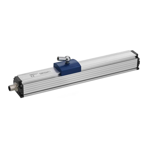
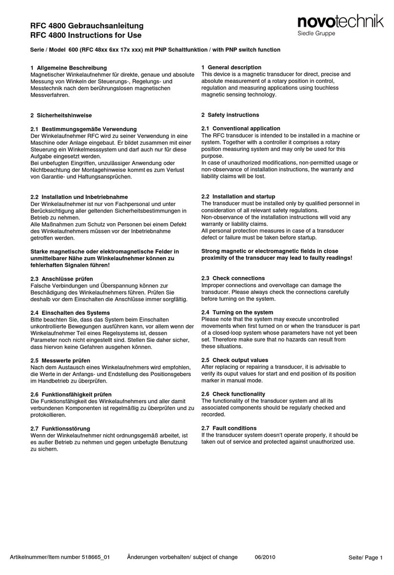
novotechnik RFC-4800 User manual

P/N: 403001637_02 Änderungen vorbehalten / subject to change 02/2018
1Allgemeine Beschreibung
Magnetischer Winkelaufnehmer für direkte, genaue und
absolute Messung von Winkeln der Steuerungs-, Regelungs-
und Messtechnik nach dem kontaktlosem Hall-Effekt
Messverfahren.
2Sicherheitshinweise
2.1 Bestimmungsgemäße Verwendung
Der Winkelaufnehmer wird zu seiner Verwendung in eine
Maschine oder Anlage eingebaut. Er bildet zusammen mit
einer Steuerung ein Winkelmesssystem und darf auch nur für
diese Aufgabe eingesetzt werden.
Unbefugte Eingriffe, nicht bestimmungsgemäße
Verwendung oder Nichtbeachtung der Montagehinweise
führen zum Verlust von Gewährleistungs-, Garantie- und
Haftungsansprüchen.
Weitere Hinweise zum sicheren Betrieb des Sensors in
Kapitel 5.
2.2 Installation und Inbetriebnahme
Der Winkelaufnehmer ist nur von Fachpersonal und unter
Berücksichtigung aller geltenden Sicherheitsbestimmungen in
Betrieb zu nehmen.
Alle Maßnahmen zum Schutz von Personen und Sachen bei
einem Defekt des Winkelaufnehmers müssen vor der
Inbetriebnahme getroffen werden.
Starke magnetische oder elektromagnetische Felder in
unmittelbarer Nähe zum Winkelaufnehmer können zu
fehlerhaften Signalen und gefährlichen Zuständen führen!
Produktvarianten mit zusätzlicher interner Abschirmung gegen
extrene magnetische Felder auf Anfrage.
2.3 Anschlüsse prüfen
Falsche Verbindungen und Überspannung können zur
Beschädigung des Winkelaufnehmers führen. Prüfen Sie
deshalb vor dem Einschalten die Anschlüsse immer sorgfältig.
2.4 Einschalten des Systems
Das System kann beim Einschalten unkontrollierte
Bewegungen ausführen, vor allem wenn der
Winkelaufnehmer Teil eines Regelsystems ist, dessen
Parameter noch nicht eingestellt sind. Stellen Sie daher
sicher, dass hiervon keine Gefahren für Personen und
Sachen ausgehen können.
2.5 Messwerte prüfen
Nach dem Austausch eines Winkelaufnehmers wird empfohlen,
die Ausgangswerte in der Anfangs- und Endstellung des
Positionsgebers im Handbetrieb zu überprüfen
(Änderungen oder fertigungsbedingte Streuungen
vorbehalten).
2.6 Funktionsfähigkeit prüfen
Die Funktionsfähigkeit des Winkelaufnehmers und aller damit
verbundenen Komponenten ist regelmäßig zu überprüfen und
zu protokollieren.
2.7 Funktionsstörung
Wenn der Winkelaufnehmer nicht ordnungsgemäß arbeitet, ist
es außer Betrieb zu nehmen und gegen unbefugte Benutzung
zu sichern.
2.8. Begrenzung Einsatzbereiche
Unsere Produkte sind regelmäßig nicht für Luft- und
Raumfahrtanwendungen zugelassen und dürfen nicht in
kerntechnischen oder militärischen, insbesondere ABC-
relevanten Applikationen verwendet werden.
Weitere Informationen s. unsere AGBs.
Seite / Page 1
RFC-4800 Gebrauchsanleitung
RFC-4800 User Manual
1General description
This device is a Hall-effect, non-contact sensor for direct,
precise and absolute measurement of a rotary position in
control, regulation and measuring applications using touchless
magnetic sensing technology.
2Safety instructions
2.1 Intended conditions of use
The transducer is intended to be installed in a machine or
system. Together with a controller it comprises a rotary
position measuring system and may only be used for this
purpose.
Unauthorized modifications, improper usage or non-
observance of the instructions for installation will result in
the loss of warranty and and voids all manufacturer
liability claims.
Further instructions for safe operation pls. see chapter 5.
2.2 Installation and startup
The transducer must be installed only by qualified personnel in
consideration of all relevant safety regulations.
Non-observance of the installation instructions will void any
warranty or liability claims.
All necessary safety measures to protect personnel and
property in case of a transducer defect or failure must be
taken before startup.
Strong magnetic or electromagnetic fields in close
proximity of the transducer may lead to faulty signals and
dangerous states!
Product models with additional internal shielding against
external magnetic fields on request.
2.3 Check connections
Improper connections and overvoltage can damage the
transducer. Please always check the connections carefully
before turning on the system.
2.4 Turning on the system
The system may execute uncontrolled movements
during first turning-on mainly when the transducer is part
of a control system whose parameters have not yet been
set. Therefore make sure that hereof no dangers for
personnel and property can result.
2.5 Check output values
After replacement of a transducer, it is advisable to verify the
output values for start- and end position of the sensor shaft in
manual mode (transducers are subject to modification or
manufacturing tolerances).
2.6 Check functionality
The functionality of the transducer system and all its
associated components should be regularly checked and
recorded.
2.7 Failure malfunction
If the transducer system doesn‘t operate properly, it should be
taken out of service and protected against unauthorized use.
2.8. Limitations for application
Our products are regularly not approved for aeronautic or
aerospace applications and are not allowed to be used in
nuclear or military, in particular ABC-relevant applications.
For more information see our Terms and Conditions.
Analogvarianten / Versions with analog interface
P/N: 403001637_02 Änderungen vorbehalten / subject to change 02/2018
3 Montagehinweise
Alle relevanten Dimensionen siehe Zeichnung im Datenblatt.
Montage Sensorgehäuse ausschließlich mit den mitgelieferten
Linsenflanschkopfschrauben M4, Drehmoment max. 250 Ncm.
Die Montage des zugehörigen Positionsgebers erfolgt nach
den diesem zugeordneten Anweisungen.
3 Instructions for installation
All relevant dimensions see drawing in data sheet
Mounting of the sensor housing using only the delivered
button head socket screws M4, torque force max. 250 Ncm.
The mounting of the corresponding position marker follows
the instructions given with it.
Für optimale Zentrierung des Sensorgehäuses können
die 2 Zentrierbohrungen (s. Kap. 3.1) genutzt werden. For optimal centering of the sensor, it‘s 2 centering holes
can be used (see chapter 3.1).
Vorsicht ! Nichtfluchtender Einbau des Sensors in
Bezug auf die Antriebswelle (=Positionsgeber) und
Nichtbeachten des Arbeitsbereiches des
Positionsgebers bzw. Magneten kann zu
zusätzlichen Linearitätsfehlern und in Folge zu
gefährlichen Zuständen führen !
Caution ! If the sensor is not properly aligned
with respect to the drive shaft (=position
marker) or the working distance of the position
marker is not correct, this can lead to
additional linearity errors and to dangerous
states !
Vorsicht ! Ein Lösen der Fixierung von Sensor,
Positionsgeber oder Klebung des Magneten
(auch als Bestandteil des Positionsgebers) kann
zu gefährlichen Zuständen führen !
Caution ! A loosening of the fixation of the
sensor, the position marker or the glue fixation
of the magnet (also as part of the position
marker) can lead to dangerous states !
Vorsicht ! Der Sensor darf auf keinen Fall
geöffnet werden ! Caution ! The sensor must not be opened at any
time !
Beim Reinigen ist dauerhaftes Druckwasser
(Hochdruckreiniger) auf die passive Seite des
Sensors zu vermeiden!
Druckstrahl auf das Etikett kann die Beschriftung
unleserlich machen !
At cleaning, steady pressure water (pressure
wash) on the passive side of the sensor has to
be avoided !
Pressure water can dissolve the text on label !
Für Montagehinweise und Arbeitsbereiche zum
jeweiligen Positionsgeber bitte separate
Montageanleitung beachten !
For mounting instructions / operating ranges of
position markers please refer to it‘s
corresponding instructions of use.
Für fehlerfreie Funktion muss gewährleistet sein,
dass der Bereich zwischen Sensor und
Positionsgeber frei von magnetisch leitfähigen oder
magnetischen Partikeln (z.B. Eisenspäne) ist !
For error-free function, it has to be ensured that
in the space between sensor and position marker
there are no magnetic conductive or magnetic
material (iron flakes etc.).
Nur die im Datenblatt genannten Positionsgeber
von Novotechnik dürfen verwendet werden ! Only position markers from Novotechnik
mentioned in the data sheet are allowed to be
used !
RFC-4800 Gebrauchsanleitung
RFC-4800 User Manual
Die angegebene Schutzart gilt nur im gesteckten
Zustand. The specified protection class is valid only when
plugged in.
Der Mindest-Biegeradius des Kabels beträgt 40mm. Ein
dauernder Zug auf das Anschlusskabel in jeglicher Richtung ist
zu vermeiden.
Wenn das Kabel im Gebrauch bewegt wird, muss es zur
Zugentlastung nach dem Austritt fixiert werden
(Schelle o.ä.).
Kabelanschlüsse müssen so montiert werden, dass
keine Feuchtigkeit ins Kabel eindringen kann
Minimum bending radius of the cable is 40mm. Avoid steady
tension on the cable in any direction.
If the cable is moving in the application, appropriate
action is to be taken to fix the cable after the outlet of
the sensor (use of fixation clamp or similar).
Cable connections must be installed in the way that the
ingress of moisture into to cable is avoided.
P/N: 403001637_02 Änderungen vorbehalten / subject to change 02/2018
Für optimale Zentrierung des Sensorgehäuses
kann dessen Außendurchmesser (48,0 mm)
oder die Zentrierbohrungen (2,0 mm) genutzt
werden.
For optimal centering of the sensor, it‘s outer
diameter (48.0 mm) or the centering holes
(2.0 mm) can be used.
Seite / Page 3
RFC-4800 Gebrauchsanleitung
RFC-4800 User Manual
3.1.1 Montagebeispiele Sensor –Positionsgeber / Mounting examples sensor - position marker
3.1 Maße und Montage des Sensors / Dimensions and Mounting of the Sensor
Kabel
Cable Einzeladern
Lead wires M12 Stecker
M12 connector
Beispiel A
Example A
Aktive Seite
Active side
Beispiel C: Positionsgeber durch Platte
Example C: Position marker through plate
Aktive Seite
Active side
Beispiel B: medienisoliert
Example B: media isolated
Nichtmagnetisches
Material verwenden !
Use non magnetic
material !
Aktive Seite
Active side
AMP Stecker
AMP connector
Rundloch
Round hole
Langloch
Elogated hole
Zentrierbohrungen
(3,15 ±0,1 tief)
Centering holes
(3.15 ±0.1 deep)
Grundsätzliche Anordnung Sensor zu Positionsgeber.
Die aktive Seite des Sensors ist die unvergossene Seite,
welche immer zum Positionsgeber zeigen muss.
Basic setup of sensor with respect to position marker.
The active side of the Sensor is the non potted side and
has always to be where the position marker is.
Für Montagehinweise und Arbeitsbereiche zum jeweiligen
Positionsgeber (Maß A) bitte separate Montageanleitung
beachten
For mounting instructions / operating ranges of position
marker (dimension A) please refer to its corresponding
instructions of use.
P/N: 403001637_02 Änderungen vorbehalten / subject to change 02/2018
Cable: CE: shielded cable 0.5 mm² (AWG 20)
Cable shield has to be connected to ground.
Extension of shielded cable demands a sufficient
shielding !
Elongation of the cable beyond 30m will void the
CE approval..
Mobil: unshielded cable 0.5 mm² (AWG 20)
Connections with the label „do not connect“ must
be isolated !
Lead wires: 0.5mm² (AWG 20)
Seite / Page 4
RFC-4800 Gebrauchsanleitung
RFC-4800 User Manual
4.1 Output signal
4Elektrische Daten / Electrical data
4.1 Ausgangssignal
Kennlinienausrichtung:
zeigt die Markierung am Positionsgeber
in Richtung elektrischem Anschluss,
befindet sich der Sensor auf Kennlinienmitte.
Output characteristic:
when the marking of the position marker is
pointing to electrical outlet, the output signal is
near electrical center postion.
Mehrkanalig / redundantEinkanalig / single
5.2 Elektrische Anschlüsse 5.2 Electrical connections
Kabel: CE: geschirmte Leitung 0,5 mm² (AWG 20)
Der Kabelschirm ist an Masse anzuschließen.
Bei Verlängerung ist auf ausreichende Schirm-
dämpfung zu achten !
Bei Verlängerung des Anschlusskabels über > 30 m
erlischt die CE-Freigabe.
Mobil: ungeschirmte Leitung 0,5 mm² (AWG 20)
Anschlüsse mit dem Hinweis „nicht anschließen“
müssen isoliert werden !
Einzeladern: 0,5mm² (AWG 20)
Einzeladern
Lead wires
Kabel
Cable
Stecker
Plug
Signal
Signal
RD rot / r
ed
GN grün / green
PIN 1
Ub
BU blau /
blue
WH weiß / white
PIN 2
Signal 1
BK schwarz /
black
BN braun /
brown
PIN 3
GND
-
YE gelb / yellow
PIN 4
nicht
anschliessen / do not connect
Single / single RFC-48__-6__ -___-___
Mehrkanalig / redundant RFC-48__-7 / 8__ -___-___
Einzeladern
Lead wires
Kabel
C
able
Stecker
Plug
Signal
Signal
RD
rot / red
GN grün /
green
PIN 1
Ub 1
BU
blau / blue
WH weiß /
white
PIN 2
Signal 1
BK
schwarz / black
BN braun /
brown
PIN 3
GND 1
BU/WH blau
-weiss / blue-white
YE gelb /
yellow
PIN 4
Signal 2
RD/WH rot
-weiss / red-white
-
-
Ub 2
BK/WH
schwarz-weiss / black-white
-
-
GND 2
Bestellcode
Ordering
code
Versorgung
Supply
voltage
Stromaufnahme pro Kanal
Current
draw per channel
Spannungsausgang:
Lastwiderstand
Voltage
Output:
Load
Stromausgang:
Bürde
Current
Output:
Burden
Signal bei Kabelbruch
Output at cable break
RFC
-48__-___-11_-
___
24 VDC
(18 … 30 VDC)
typ. 12 mA ohne Last
typ. 12 mA w/o load
≥ 10 k
Ω ≤ 100 kΩ
(
Pulldown)
-
< 100
mV
RFC
-48__-___-12_-___
24 VDC (13 ... 30 VDC)
-
10 … 500 Ω
< 3,5 mA
RFC
-48__-___-2__-___
5 VDC (
4,5 … 5,5 VDC)
≥
5 kΩ (Pulldown)
-
Break GND: > 95 % Ub
Break Ub: < 5% Ub
RFC
-48__-___-3__-
___
12/24 VDC (8 … 34 VDC)
≥ 10 k
Ω ≤ 100 kΩ
(
Pulldown)
≤ 13 V: 10 ... 250 Ω
> 13 V: 10 ... 500 Ω
< 100 mV , <
3,5 mA
P/N: 403001637_02 Änderungen vorbehalten / subject to change 02/2018
5.1 Intended use, conformity
The rotary position measuring system in a redundant
version can be used for measuring rotary positions of
machine elements that comply to the special
requirements of safety related applications.
The use of the transducer in a safety related application
must be judged and validated by the system integrator
according to the criteria of DIN EN ISO 13849-1.
In a 2-channel-architecture (2oo2D) this is possible up to
Category 3 / Performance Level d according to DIN EN
ISO 13849.
5.1 Einsatzbereich, Konformität
Das Winkelmesssystem in redundanter Ausführung
kann zur Positionserfassung von
Maschinenelementen, welche den besonderen
Anforderungen von sicherheitsgerichteten
Anwendungen genügt, eingesetzt werden.
Der Einsatz des Winkelaufnehmers in einer
sicherheitsbezogenen Applikation muss vom
Systemintegrator nach den Kriterien der DIN EN ISO
13849-1 bewertet und validiert werden.
In einer zweikanaligen Architektur (2oo2D) ist dies bis
Kategorie 3 bzw. Performance Level d gemäß DIN EN
ISO 13849-1 möglich.
5.2 Relevante Normen
DIN EN ISO 13849-1
2006/42/EG
Beispiel: System mit einer Architektur 2oo2D
empfohlen für Kategorie 3
Der Winkelaufnehmer ist kein Logikelement gemäß
Maschinenrichtlinie 2006/42/EG, Anhang IV, Punkt 21.
5.2 Relevant Directives
DIN EN ISO 13849-1
2006/42/EG
Example: System 2oo2D recommended for Category 3
The rotary position transducer is no logical element acc.
To machinery directive 2006/42/EG, Attachment IV,
Chapter 21.
5 Erweiterte Kenndaten zum Einsatz des
Winkelaufnehmers als Subsystem in
sicherheitsrelevanten Applikationen
Legende
imVerbindungsmittel
c Kreuzvergleich z.B. durch Bildung eines
Summensignals
I1, I2 Eingabeeinheiten Winkelaufnehmer RFC
L1, L2 Logik
m Überwachung
O1, O2 Ausgabeeinheiten (Aktoren, ..)
Legend
imConnection
c Cross comparison, for example by generation of a
sum of both signals
I1, I2 Input units

transducer RFC
L1, L2 Logic unit
m Surveillance
O1, O2 Output units (actuators, ..)
I1 L1 O1
im im
m
I2 L2 O2
im im
m
c
Winkelaufnehmer RFC-4800
redundante Ausführung
Rotary transducer RFC-4800
redundant version
5 Extended data for the use of the sensor as a
subsystem in safety relevant applications
This chapter is only valid for analog sensor models
with 2 crossed outputs and activated diagnosis !!
Dieser Abschnitt gilt nur für analoge Versionen
des Winkelsensors mit 2 gekreuzten
Sensorausgängen und aktivierter Diagnose !!
RFC-4800 Gebrauchsanleitung
RFC-4800 User Manual
Seite / Page 5

Other novotechnik Accessories manuals

novotechnik RSX-7900 Series User manual

novotechnik

novotechnik RSX-7900 Series User manual

novotechnik RFC 4800 User manual

novotechnik

novotechnik RFC 4800 User manual

novotechnik TEX series User manual

novotechnik

novotechnik TEX series User manual

novotechnik RFC-4800 User manual

novotechnik

novotechnik RFC-4800 User manual

novotechnik RSX-7900 User manual

novotechnik

novotechnik RSX-7900 User manual

novotechnik RSC 3202 User manual

novotechnik

novotechnik RSC 3202 User manual

novotechnik LWH Series User manual

novotechnik

novotechnik LWH Series User manual

novotechnik RSC-2800 User manual

novotechnik

novotechnik RSC-2800 User manual

novotechnik TP1 CANopen User manual

novotechnik

novotechnik TP1 CANopen User manual

Popular Accessories manuals by other brands

Quincy lab 140AE-1 operating manual

Quincy lab

Quincy lab 140AE-1 operating manual

HomePro ZIR000 user manual

HomePro

HomePro ZIR000 user manual

DOL 20SCR Technical user guide

DOL

DOL 20SCR Technical user guide

RAB Smart Task installation manual

RAB

RAB Smart Task installation manual

Kemppi KMS 300 quick guide

Kemppi

Kemppi KMS 300 quick guide

Stearns 57,500 Series Installation and service instructions

Stearns

Stearns 57,500 Series Installation and service instructions

iGuzzini TWILIGHT COPENAGHEN manual

iGuzzini

iGuzzini TWILIGHT COPENAGHEN manual

Adelaide Annexe & Canvas Avan Deluxe installation guide

Adelaide Annexe & Canvas

Adelaide Annexe & Canvas Avan Deluxe installation guide

OHAUS 5000 instruction manual

OHAUS

OHAUS 5000 instruction manual

HOME8 WLS1300 quick start guide

HOME8

HOME8 WLS1300 quick start guide

MAXBOTIX MaxSonar quick start guide

MAXBOTIX

MAXBOTIX MaxSonar quick start guide

ioSmart iSmart56 Installation and user guide

ioSmart

ioSmart iSmart56 Installation and user guide

Focusrite Scarlett 18i8 user guide

Focusrite

Focusrite Scarlett 18i8 user guide

Velleman ED38105 user manual

Velleman

Velleman ED38105 user manual

JumpSport SkyBounce user manual

JumpSport

JumpSport SkyBounce user manual

Prima-Temp PRIYA Instructions for use

Prima-Temp

Prima-Temp PRIYA Instructions for use

Tefcold BC85I-BC85I W user manual

Tefcold

Tefcold BC85I-BC85I W user manual

Vaisala WMS302 user guide

Vaisala

Vaisala WMS302 user guide

manuals.online logo
manuals.online logoBrands
  • About & Mission
  • Contact us
  • Privacy Policy
  • Terms and Conditions

Copyright 2025 Manuals.Online. All Rights Reserved.