manuals.online logo
Brands
  1. Home
  2. •
  3. Brands
  4. •
  5. novotechnik
  6. •
  7. Accessories
  8. •
  9. novotechnik TP1 CANopen User manual

novotechnik TP1 CANopen User manual

Page 1
1General description 2
2Safety instructions 2
2.1 Intended conditions of use 2
2.2 Installation & startup 2
2.3 Check connections 2
2.4 Turning on the system 2
2.5 Check measured values 2
2.6 Check functionality 2
2.7 Failure malfunction 2
3 Electrical data 3
4Instructions for installation 3
5 Wiring 3
6 Mounting and installation 4
6.1 Transducer 4
6.2 Position marker 5
6.2.1 Z-TP1-P06 5
6.2.2 Z-TP1-P07 5
6.2.3 Z-TP1-P08 5
7 Electrical connection 6
7.1 M16x0.75 (Code 105) 6
7.2 M12x1 (Code 106) 7
8 CANopen interface 7
9 Required accessories
8
10 Optional accessories 8
11
Ordering code 8
1概要 2
2安全上のご注意 2
2.1 使用目的 2
2.2 インストールと起動 2
2.3 接続を確認する 2
2.4 システムの電源を入れる 2
2.5 測定値を確認する 2
2.6 機能を確認する 2
2.7 故障誤動作 2
3電気的データ 3
4インストール手順 3
5配線 3
6 取付とインストール 4
6.1 トランスデューサ 4
6.2 ポジションマーカー 5
6.2.1 Z-TP1-P06 5
6.2.2 Z-TP1-P07 5
6.2.3 Z-TP1-P08 5
7電気接続 6
7.1 M16x0.75 ( コード 105) 6
7.2 M12x1 ( コード 106) 7
8 CANopen
インターフェース
7
9
必要なアクセサリ
8
10 オプションのアクセサリ 8
11 注文コード 8
TP1 CANopen ユーザーズマニュアル / TP1 CANopen User Manual
1 General description
The TP1 series is a magnetostricitve transducer for direct,
accurate measurement of travel in display- or feedback applications.
2 Safety instructions
Our products are regularly not approved for aeronautic or
aerospace applications and are not allowed to be used in
nuclear or military, in particular ABC-relevant applications.
For more information see our Terms and Conditions.
2.1 Intended use
The transducer is intended to be installed in a machine or system.
Together with a controller (e.g. PLC) it comprises a position measuring system and may only be
used for this purpose.
Unauthorized modications, improper usage or nonobservance of the instructions for installation
will result in the loss of warranty and liability claims.
2.2 Installation & startup
The transducer must be installed by qualied personnel in consideration of all relevant
safety regulations.
All necessary safety measures to protect personnel and property in case of a transducer
defect or failure must be taken before startup.
   
2.3 Check connections
Improper connections and overvoltage can damage the transducer.
Check the connections always carefully before turning-on system.
     Potential dierences between supply voltage
     GND and signal GND must be avoided.
     With dierent potentials between supply voltage
     GND and signal GND the transducer can be destroyed!
2.4 Turning on the system
   The system may execute uncontrolled movements during rst  
   turning-on mainly when the transducer is part of a control system
whose parameters have not yet been set. Therefore make sure that
hereof no dangers for personnel and property can result.
2.5 Check measured values
After replacement of a transducer, it is advisable to verify the output
values for start- and end position of the position marker in manual mode.
(Transducers are subject to modication or manufacturing tolerances)
2.6 Check functionality
The functionality of the transducer system and all its associated
components should be regularly checked and recorded.
2.7 Failure malfunction
If the transducer system doesn ‘t operate properly, it should be taken
out of service and protected against unauthorized use.
1 概要
TP1 シリーズは、制御、調整に用いられる高精度アブソリュートタイプの
磁歪変位トランスデューサです。
2 安全上のご注意
当社の製品は、航空または航空宇宙用途では定期的に承認されておらず、
原子力または軍事、特に ABC 関連の用途での使用は許可されていません。
詳細については、利用規約をご覧ください。
2.1 使用目的
トランスデューサは、機械またはシステムに設置することを目的としています。
コントローラー(PLC 等)と一緒に位置測定システムを構成し、この目的に
のみ使用できます。
改造、不適切な使用、またはインストール手順の不遵守は、
保証の喪失につながり、責任請求を無効にします。
2.2 インストールと起動
トランスデューサは、関連するすべての安全規制を考慮して、資格のある担当
者が設置する必要があります。
トランスデューサの欠陥または故障の場合に人員と財産を保護するために必要
なすべての安全対策は、起動前に実行する必要があります。
   
2.3 接続を確認する
不適切な接続と過電圧は、トランスデューサを損傷する可能性があります。
システムの電源を入れる前に、必ず接続を注意深く確認してください。
供給電圧 GND と信号 GND の電位差は避けてください。
供給電圧 GND と信号 GND の間の電位が異なると、
トランスデューサが破壊される可能性があります。
2.4 システムの電源を入れる
   システムは、特にトランスデューサのパラメータがまだ設定されて
いない制御システムの一部である場合、最初の電源投入時に制御されて
いない動作を実行する場合があります。
したがって、これが人員や財産に危険が及ばないようにしてください。
2.5 測定値を確認する
トランスデューサの交換後は、手動モードでポジションマーカーの開始位置と
終了位置の出力値を確認することをお勧めします。
(トランスデューサは変更または製造公差の対象となります)
2.6 機能を確認する
トランスデューサとそれに関連するすべてのコンポーネントの機能を定期的に
チェックしてください。
2.7 故障誤動作
トランスデューサが適切に動作しない場合は、使用を停止し、不正使用から
保護してください。
Page 2
TP1 CANopen ユーザーズマニュアル / TP1 CANopen User Manual
Page 3
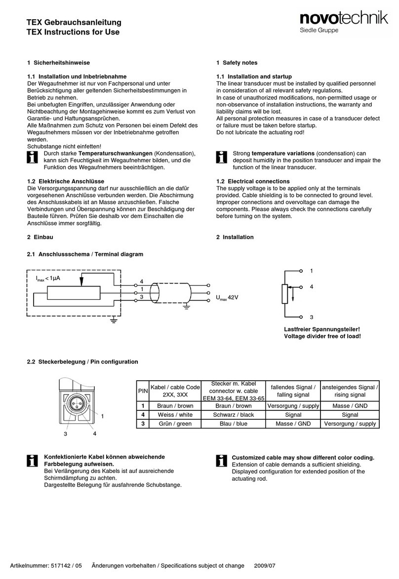
3 電気的データ / Electrical data
供給電圧 /Supply voltage: 24 VDC ( データシートも参照 /see also data sheet)
消費電流 /Current consumption: ≤ 100mA 一般的 /typical
4 Instruction for installation
The maximum torque of 200 Ncm is to be considered by
assembling of the mounting clamps.
It is recommended to place the mounting clamps in constant distances.
The position marker (accessory) is installed at a distance to
the prole surface according to item 6.2.
For the mounting of the position marker and the xing via screws (M4)
non-magnetic material (e.g. stainless steel, brass, aluminum) should be
used preferably.
In order to ensure the accuracy of the transducer, the oating position
marker must be guided parallel to the prole surface.
   Strong electrical or magnetic elds in the immediate vicinity of
the transducer may lead to faulty signals!
For the area of the cable please take care that enough
space is available, the minimum bending radius has been
observed and sharp edges have be avoided!
For the versions with several position markers the distance between
the position markers must be min. 100 mm!
5 Wiring
Note the following when making electrical connection:
System (supply voltage GND) and control cabinet (signal GND) must be
at the same potential.
To ensure the electromagnetic compatibility (EMC), the following
instructions must be strictly followed:
•
Transducer and controller must be connected by using a shielded cable.
• Shielding: Copper lament braided, 85% coverage.
• On the controller side the cable shield must be grounded,
 i.e. be connected with the protective earth conductor.
   Cable connection may not extended over 30m!
4 インストール手順
固定クリップを組み立てるときは、最大トルク 200Ncm を遵守する必要が
あります。
取り付けブラケットは等間隔で配置することをお勧めします。
ポジションマーカー(アクセサリ)は、セクション 6.2 に従ってプロファイ
ル面から離れた場所に取り付けます。
ポジションマーカーとネジによる固定(M4)は、非磁性材料(ステンレス鋼、
真ちゅう、アルミニウムなど)で作成する必要があります。
位置トランスデューサの精度を確保するには、ポジションマーカーを
プロファイル面と平行にガイドする必要があります。
 
 トランスデューサのすぐ近くに強い電界または磁界があると、信号に障害が
発生する可能性があります。
接続ケーブルの設置の際は、十分にスペースを設けてください。最小曲げ半径
を遵守し、鋭いエッジを避ける必要があります。
複数のポジションマーカーを備えたバージョンの場合、
ポジションマーカー間の距離は少なくとも 100mm でなければなりません。
5 配線
電気接続を行うときは、次の点に注意する必要があります。
システム(電源 GND)と制御キャビネット(信号 GND)は
同じ電位である必要があります。
電磁両立性(EMC)を保証するために、以下の指示を遵守する必要があります:
•
位置トランスデューサと制御装置は、シールドケーブルで接続する必要があります。
• シールド:個々の銅線の編組、85%の被覆率。
• 制御側では、ケーブルシールドを接地する必要があります。
 つまり、保護導体に接続する必要があります。
ケーブル接続は 30m 以上を超えて延長はすることはできません。
TP1 CANopen ユーザーズマニュアル / TP1 CANopen User Manual
6 インストール / Installation
Page 4
6.1 トランスデューサ / Transducer
納品に含まれるもの:スチール製取り付けクランプ Z-46 を含むヘッドキャップネジ M5x20。
Included in delivery: steel mounting clamps Z-46 incl. head cap screws M5x20
TP1 CANopen ユーザーズマニュアル / TP1 CANopen User Manual
注文コードの例
マーキング:電気的ゼロ点
マーキング:電気的ゼロ点 アクセサリ:ポジションマーカー
最大締付トルク 200Ncm /
6.2 ポジションマーカー / Position markers
6.2.1 Z-TP1-P06 (P/N 005693); フローティングポジションマーカー /oating position marker
Page 5
電気的ゼロ点
電気的ゼロ点
電気的ゼロ点 ポジションマーカーを回転させると、
軸ずれが 26.6mm になります。
6.2.2 Z-TP1-P07 (P/N 005694); フローティングポジションマーカー /oating position marker
6.2.3 Z-TP1-P08 (P/N 005695); ガイド付きポジションマーカー /guided position marker
TP1 CANopen ユーザーズマニュアル / TP1 CANopen User Manual
マーク
7 電気接続 / Electrical connection
Page 6
TP1 CANopen ユーザーズマニュアル / TP1 CANopen User Manual
M16 × 0.75 6 ピンフランジコネクタ
注文コードの例
       ピン構成  
 フランジコネクタの正面図
供給電圧 Ub / Supply Ub 
シールド / shield
接続なし / do not connect
  ピン割り当て / Pin assignment  
信号 /  Signal
  M16 コネクタ / M16 connector
  コード
ピン 5 / pin 5
ピン 6 / pin 6
ピン 2 / pin 2
ピン 1 / pin 1
ピン 3 / pin 3
ピン 4 / pin 4
7 電気接続 / Electrical connection
Page 7
TP1 CANopen ユーザーズマニュアル / TP1 CANopen User Manual
M12 × 1 5 ピンフランジコネクタ
注文コードの例
       ピン構成  
 フランジコネクタの正面図
供給電圧 Ub / Supply Ub 
シールド / shield
  ピン割り当て / Pin assignment  
信号 /  Signal
  M12 コネクタ / M12 connector
  コード
ピン 5 / pin 5
ピン 2 / pin 2
ピン 1 / pin 1
ピン 3 / pin 3
ピン 4 / pin 4
CANopen インターフェースと電子データシート(EDS)の説明は、Novotechnik ホームページの [ ダウンロード / 使用方法 ] からダウンロードできます。
The description of CANopen interface and the electronic data sheet (EDS) can be downloaded from Novotechnik web site,
see Downloads/Operating manuals.
8 CANopen インターフェース / CANopen interface
Page 8
9 Required Accessories
• Position marker Z-TP1-P06, P/N 005693
• Position marker Z-TP1-P07, P/N 005694
• Guided position marker Z-TP1-P08, P/N 005695
10 Optional accessories
• Actuating rod Z-TP1-S01- _ _ _ _ ,
for guided position marker Z-TP1-P08,
standard nominal length from 0075 - 2000mm.
• 2x Standard steel mounting clamps Z-46
incl. 4x cylinder screws M5x20, P/N 056029
• Mating female connector, straight
M16x0.75 (IEC 130-9):6-pin,
EEM 33-82, P/N 005639
• Mating female connector, angled M16x0.75 (IEC 130-9):6-pin,
EEM 33-94, P/N 005648
• Mating female connector, straight, M12x1, 5-pin,
for wire gauge 6...8 mm, max. 0.75 mm²,
EEM 33-73, P/N 005645
• Mating female connector, angled M12x1; 5-pin,
for wire gauge 6...8 mm, max. 0.75 mm²,
EEM 33-75, P/N 005646
• Cable set - female connector M12x1, 5-pin, CAN-Bus
straight, with molded PUR-cable, IP67, open-ended:
2m length, EEM 33-41, P/N 056141
5m length, EEM 33-42, P/N 056142
10m length, EEM 33-43, P/N 056143
• Cable set – male/female connector M12x1, 5-pin, CANBus, straight,
with molded PUR-cable, IP68:5m length,
EEM 33-44, P/N 056144
• Splitter/T-Connector, 1:1 connection, M12x1, 5-pin, with
one M12 male and two M12 female connectors:
EEM 33-45, P/N 056145
• Terminating resistor, M12x1, 5 poles,
male connector, CAN-Bus, 120 Ω :
EEM 33-47, P/N 056147
9 必要なアクセサリ
• ポジションマーカー  Z-TP1-P06, P/N 005693
• ポジションマーカー  Z-TP1-P07, P/N 005694
• ガイド付きポジションマーカー Z-TP1-P08, P/N 005695
10 オプションアクセサリ / Optional accessories
• 作動ロッド Z-TP1-S01-_ _ _ _、
ガイド付きポジションマーカー Z-TP1-P08 の場合、
標準の公称長さは 0075 〜 2000mm です。
•Z-46 × 2 標準スチール取り付けクランプ、
M5x20 × 4 シリンダーネジ、 P / N 056029 付属
•M16x0.75(IEC 130-9):6 ピン 嵌合メスコネクタ、ストレート
EEM 33-82、P / N 005639
•M16x0.75(IEC 130-9):6 ピン嵌合メスコネクタ、アングル
EEM 33-94、P / N 005648
• M12x1、5 ピン嵌合メスコネクタ、ストレート
ワイヤーゲージ 6 ... 8 mm、最大 0.75mm²
EEM 33-73、P / N 005645
• M12x1、5 ピン嵌合メスコネクタ、アングル
ワイヤーゲージ 6 ... 8 mm、最大 0.75mm²
EEM 33-75、P / N 005646
•M12x1、5 ピン ケーブルセットメスコネクタ、 ストレート、CAN-Bus
成形 PUR ケーブル、IP67、オープンエンド:
長さ 2m、EEM 33-41、P / N 056141
長さ 5m、EEM 33-42、P / N 056142
長さ 10m、EEM 33-43、P / N 056143
• M12x1、5 ピン ケーブルセットオス / メスコネクタ、ストレート、
CAN-Bus 成形 PUR ケーブル付き、IP68:
長さ 5m、EEM 33-44、P / N 056144
• スプリッター / T コネクタ M12、5 ピン オスコネクタ× 1、
M12、メスコネクタ× 2 付属:
EEM 33-45、P / N 056145
• M12x1、5 極、オスコネクタ、CAN-Bus、終端抵抗、120 Ω:
EEM 33-47、P / N 056147
T P 10 0 08 1 0 1 1 3 1 0 6
6
- - - -
型式仕様
推奨品は太字で記載されています
シリーズ
電気的測定長
標準測定長 0050... 4250 mm
0050 ... 0500 mm 25 mm 毎、 0500 ... 1000 mm 50 mm 毎
1000 ... 2000 mm 100 mm 毎、 2000 ... 4250 mm 250 mm 毎
ご要望により他の長さに対応可能です。
機械的仕様
101:プロファイル形状
電気的インターフェース
6:CANopen インターフェース
1:
1 × pos. 分解能 5 μ m と 1 × vel. 分解能 0.5mm/s (1 PG x)
3:
1 × pos. 分解能 1 μ m と 1 × vel. 分解能 0.1mm/s (1 PG x)
5:
2 × pos. 分解能 5 μ m と 2 × vel. 分解能 0.5mm/s (2 PG x)
6:
2 × pos. 分解能 1 μ m と 2 × vel. 分解能 0.1mm/s (2 PG x)
電気的接続
105:1 × IEC130-9 6 ピン丸コネクタ  
106:1 × M12 5 ピン丸コネクタ  
出力信号 CANopen インターフェース 6_ _
CANopen インターフェース 6_ _
1:
ボーレート 1000kBaud、デフォルトノード ID127
2:
ボーレート 800kBaud、デフォルトノード ID127
3:
ボーレート 500kBaud、デフォルトノード ID127
4:
ボーレート 250kBaud、デフォルトノード ID127
5:
ボーレート 125kBaud、デフォルトノード ID127
7:
ボーレート 50kBaud、デフォルトノード ID127
8:
ボーレート 20kBaud、デフォルトノード ID127
9:
ボーレート 10kBaud、デフォルトノード ID127
㈱ビー・アンド・プラスは novotechnik 社の正規日本代理店です。
■各種お問合せ
㈱ビー・アンド・プラス
〒 355-0311
埼玉県比企郡小川町高谷 2452-5
E-mail:
[email protected]
T621305Aj 2021.03.25
TP1 CANopen ユーザーズマニュアル / TP1 CANopen User Manual

Other manuals for TP1 CANopen

1

Other novotechnik Accessories manuals

novotechnik RFC-4800 User manual

novotechnik

novotechnik RFC-4800 User manual

novotechnik RFC-4800 User manual

novotechnik

novotechnik RFC-4800 User manual

novotechnik RSC-2800 User manual

novotechnik

novotechnik RSC-2800 User manual

novotechnik RSX-7900 Series User manual

novotechnik

novotechnik RSX-7900 Series User manual

novotechnik RSX-7900 User manual

novotechnik

novotechnik RSX-7900 User manual

novotechnik RSC 3202 User manual

novotechnik

novotechnik RSC 3202 User manual

novotechnik RFC 4800 User manual

novotechnik

novotechnik RFC 4800 User manual

novotechnik LWH Series User manual

novotechnik

novotechnik LWH Series User manual

novotechnik TEX series User manual

novotechnik

novotechnik TEX series User manual

Popular Accessories manuals by other brands

RIB NOVA WIRELESS manual

RIB

RIB NOVA WIRELESS manual

atmosphera 148192 manual

atmosphera

atmosphera 148192 manual

Captron Electronic CHT4-2 Original operating instructions

Captron Electronic

Captron Electronic CHT4-2 Original operating instructions

Rain Bird WR2 user manual

Rain Bird

Rain Bird WR2 user manual

Orno OR-CR-227 quick start guide

Orno

Orno OR-CR-227 quick start guide

Crow TALON SERIES Installation instructions manual

Crow

Crow TALON SERIES Installation instructions manual

Pil Sensoren P41-40-I-CM12 manual

Pil Sensoren

Pil Sensoren P41-40-I-CM12 manual

Clatronic KB 3713 instruction manual

Clatronic

Clatronic KB 3713 instruction manual

Crestron (Wattstopper P/N LS-290C) Photocell Light Sensor... Operations & installation guide

Crestron

Crestron (Wattstopper P/N LS-290C) Photocell Light Sensor... Operations & installation guide

Yamaha disklavier DKC-850 Data list

Yamaha

Yamaha disklavier DKC-850 Data list

IFM LMT 0 Series operating instructions

IFM

IFM LMT 0 Series operating instructions

HOME DECÓ 50386 manual

HOME DECÓ

HOME DECÓ 50386 manual

Outdoor Revolution Compactalite Pro Integra 375 Hex instructions

Outdoor Revolution

Outdoor Revolution Compactalite Pro Integra 375 Hex instructions

HOME8 PIR1301 user manual

HOME8

HOME8 PIR1301 user manual

Siargo FS4001 user manual

Siargo

Siargo FS4001 user manual

sks 300098 installation instructions

sks

sks 300098 installation instructions

Rohde & Schwarz R&S RT-ZC15B user manual

Rohde & Schwarz

Rohde & Schwarz R&S RT-ZC15B user manual

Philips ZA675B6A Specifications

Philips

Philips ZA675B6A Specifications

manuals.online logo
manuals.online logoBrands
  • About & Mission
  • Contact us
  • Privacy Policy
  • Terms and Conditions

Copyright 2025 Manuals.Online. All Rights Reserved.