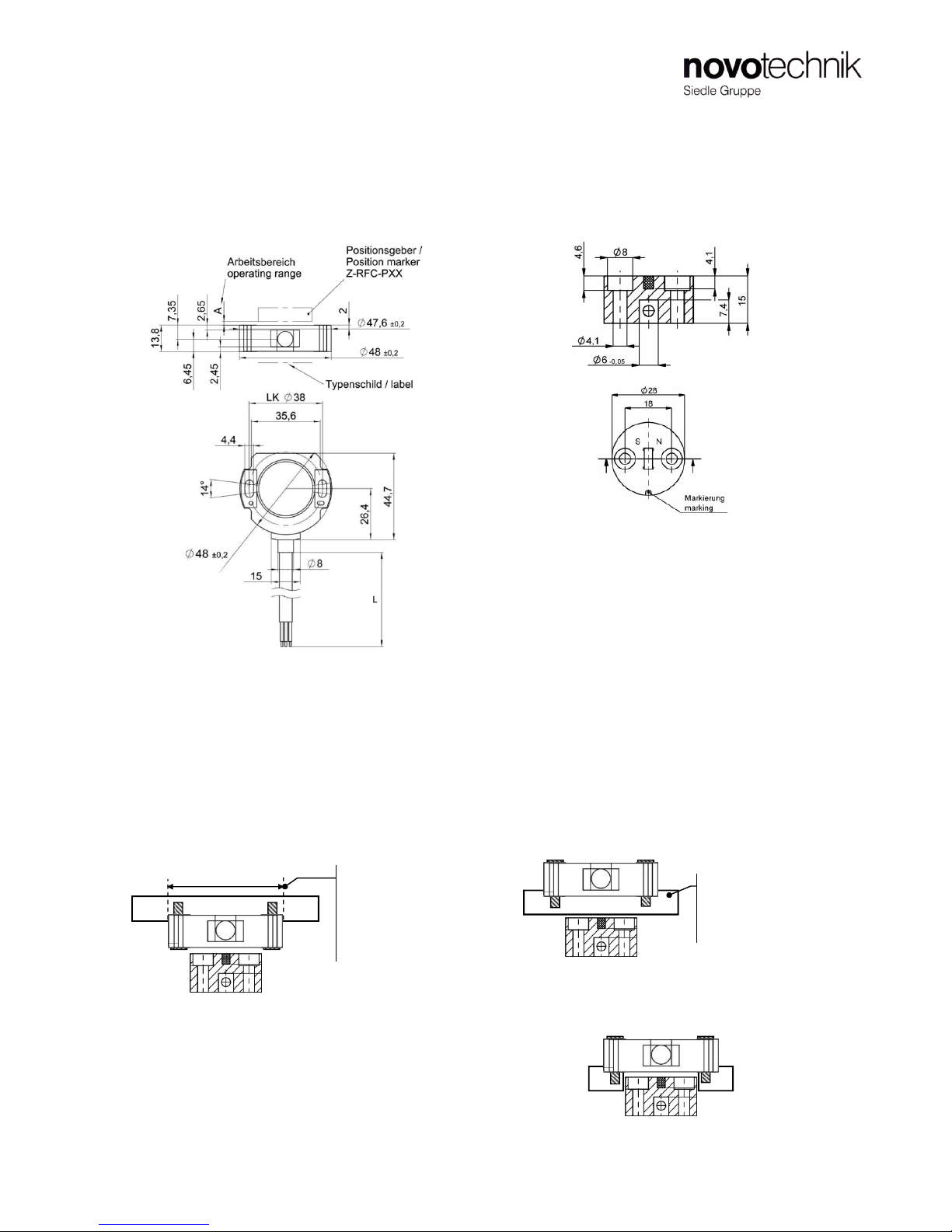
RFC 4800 Gebrauchsanleitung
RFC 4800 Instructions for Use
Serie / Model 600 (RFC 48xx 6xx 17x xxx) mit PNP Schaltfunktion / with PNP switch function
Artikelnummer/Item number 518665_01 Änderungen vorbehalten/ subject of change 06/2010 Seite/ Page 4
7.2 Bemerkungen
• Die Programmierung geschieht sehr komfortabel unter
Verwendung der Teach-In Box (Z-RFC-T01) von Novotechnik.
Hier werden die Schaltausgänge auf LED‘s und die
Programmiereingänge auf Taster geführt, was die
Benutzerführung sehr erleichtert.
Diese ist als Zubehörprodukt erhältlich.
• Die AUS-Flanke muss immer bei einem größeren
Stromausgangswert liegen als die entsprechende EIN-Flanke
• Die Ein- und Ausschaltflanken für einen Kanal können beliebig
gesetzt werden.
• Das Programmieren der Schaltausgänge kann beliebig oft
wiederholt werden.
• Auslieferungszustand für die Schaltausgänge ist:
unprogrammiert, d.h. die Schalter haben AUS-Position
7 Programmierung der Schaltpunkte der PNP-Schaltausgänge
Teach-In of the switching edges of the PNP switch outputs
7. 3 Programmierung Schaltpunkte für PNP
Schaltausgang 1 (Kanal 2 in Klammern) direkt über die
Anschlussleitungen
7.1 Grundsätzliches zur Schalterprogrammierung
Die Programmierung geschieht über 3 Steuerleitungen. Die
Menüführung während der Programmierung geschieht über die
Spannungszustände des betreffenden Schaltausganges. Es
können hierbei große Entfernungen zw. Sensor und
Porgrammier/Anzeigeeinheit überbrückt werden (bis über 10m).
Die Programmierung erfolgt über das Anlegen der
Versorgungsspannungen an die Programmierleitungen. Nach
erfolgter Programmierung können die Programmierleitungen
offen gelassen werden (interne Pull up) oder an GND
angeschlossen werden.
Wenn während der Schalterprogrammierung der Stromausgang
angeschlossen ist und z.B. über ein Voltmeter mit
Strommessung betrachtet werden kann, ist eine effektive
Positionskontrolle der Verstellmechanik möglich.
7.1 generals about Teaching the PNP switches
The Teach-In uses 3 extral electrical lines, the programming
lines. The user feedback during programming is provided by the
voltages of the switch outputs. Even large distances can be
bridged between sensor and programming/monitoring unit (up to
10m).
The Teach-In works by applying the supply voltages to the
programming lines. After programming is finished the
programming lines can be left unconnected (internal pull up) or
are connected to Ground.
It is recommended to connect and display the current output
during the teach-In procedure, for example using a DVM with
current measurement. So the actual mechanical position easily
can be controlled.
7.2 Remarks
• The Teach-In is done very comfortable when the Teach-In Box
from Novotechnik (Z-RFC-T01) is used. The switch outputs are
led to LED‘s and the programing inputs are operated by
buttons thus making the teach-in process much easier.
It is available as an add-on product.
• The OFF edge has always to be at a larger current output
value than the corresponding ON edge.
• The on/off switching edges for each channel can be chosen
freely and independently across the specified electrical range.
• The switch teach-In can be repeated very many times.
• Default setting for the switch outputs is unprogrammed. This
means the switches are OFF.
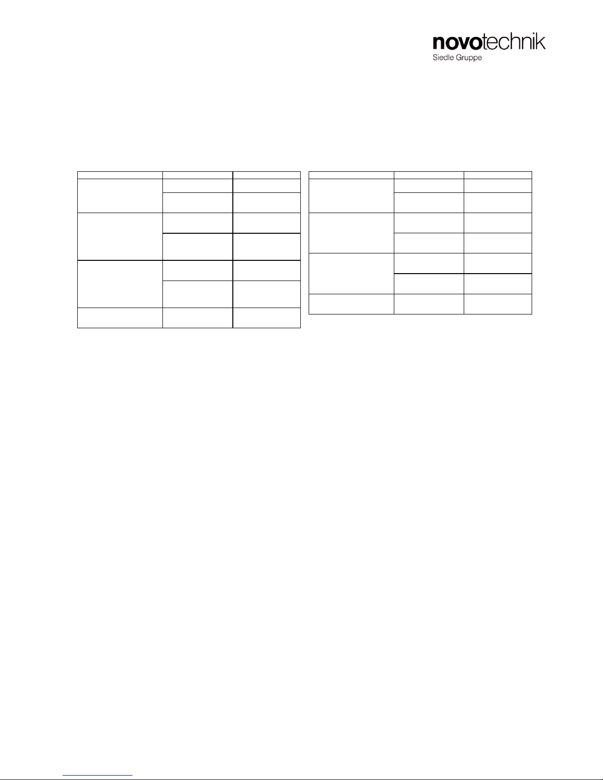
7.3 Teach-In Process for PNP Switch No. 1 (No. 2 in
Brackets) directly using the electrical lines
Teach Process s tep User action Sensor reaction
put Line Pr1 and Pr2 (Pr3) to
Ub at the same time for 3s
sw itch output 1 (sw itch
output 2) activates for ca.
2s
release line Pr1 and Pr2
(Pr3) from Ub inbetw een 2s
sw itch output 1 (sw itch
output 2) toggles fast ->
Sensor is in Programming
mode
drive position marker
mechanically to the desired
ON position
(Current output displays
actual position)
put line Pr2 shortly to Ub
sw itch output 1 (sw itch
output 2) toggles slow er
-> ON sw itching point is
teached
drive position marker
mechanically to the desired
OFF position
(Current output displays
actual position)
put line Pr3 shortly to Ub
sw itch output 1 (sw itch
output 2) becomes static
-> OFF sw itching point is
teached
4. The s witching points for
channel 1 and 2 are conpletely
teached
finished !
1. Enter programming m ode
for PNP channel 1 (channe l 2)
2. Teach ON sw itching point
3. Teach OFF sw itching point
Einstellschritt Anw e nde r Ak tion Sensor Reak tion
Leitung Pr1 und Pr2 (Pr3)
gleichzeitig für 3s an Ub
legen
Schaltausgang 1