manuals.online logo
Brands
  1. Home
  2. •
  3. Brands
  4. •
  5. Novus
  6. •
  7. Controllers
  8. •
  9. Novus N323TR User manual

Novus N323TR User manual

TEMPERATURE CONTROLLER
N323TR
OPERATING MANUAL -V1.8x E
Man 5001288
N323TR is a temperature controller for cooling systems that has a number of specially developed
functions for applications in temperature control and defrosts optimization. It presents an internal
clock for defrost schedule, with weekly schedule, daily or days or working days. It has two input
channels for temperature sensors, NTC thermistors, to measure the temperature of the supervised
environment and the evaporator module. It has three independent outputs for the control of the
compressor (cooling output), defrost module and fan.
The characteristics of the controller are in accordance with the purchase order and are shown on
the label attached to the case of the controller.
SPECIFICATIONS
SENSOR INPUT:.................................................................................................... 2 Thermistors NTC
............................................................................................................................ Type 10 k
Ω
@ 25 °C
................................................................................................... Range: –50 to 120 °C (-58 to 248°F)
......................................................................................................................Accuracy: 0.6 °C (1.1 °F)
Note: The sensors come with the equipment. Its operating range is limited to –30 to +105 °C (–222
to +221 °F). It has cable of 3 m in length, 2 x 0.5 mm², and can be extended up to 200 meters.
Maximum error in the interchangeability of original NTC sensors: 0.75 °C (33.35 °F). This error can
be eliminated through the offset parameter of the equipment.
Measurement Resolution:.................................................. 0.1 °C in the range of –19.9 to 119.9 °C
.................................................................................................................. 1 °C in the rest of the range
Note: The equipment keeps its precision all over the range, despite the lack of display resolution
in a part of the range does not allow its visualization.
OUTPUT1: ............................................... Relay SPDT; 1 HP 250 Vac / 1/3 HP 125 Vac (16 A Res.)
..................................................................Optionally: Pulse, 5 Vdc, 25 mA max.
OUTPUT2:...........................................................................................Relay SPST-NA, 3 A / 250 Vac
OUTPUT3:...........................................................................................Relay SPST-NA, 3 A / 250 Vac
POWER SUPPLY: Tension:..................................... 100 to 240 Vca/cc ±10 %
Optionally:...................................................... 12 to 30 Vdc
Frequency:.......................................................... 50~60 Hz
Consumption: ............................................................. 5 VA
Dimensions: Width x Height x Depth:.................................................... 75 x 33 x 75 mm
Weight: ...............................................................................................100 g
Panel cut-out:............................................................................70 x 29 mm
Environment: Operation temperature:...............................0 to 40 °C (32 to 104 °F)
Storage temperature: ............................... -20 to 60 °C (-4 to 140 °F)
Relative Humidity: ....................................................... 20 to 85 % UR
Case in Polycarbonate UL94 V-2; Protection: box IP42, front panel IP65;
Suitable wiring 4.0 mm²; Interface RS485 MODBUS protocol (optional);
Non-isolated serial interface input circuit. Isolated interface from the supply circuit except in the 24
V supply model.
Recommendations for the Installation
The cables of the temperature sensors must be separated from the control and power supply cables, if
possible, in grounded conduits.
The controller power supply should preferably come from an exclusive power network for the
instruments or in a different circuit from that used by the control output stage.
It is recommended to use RC filters (47 R and 100 nF, series) in coils of contactors, solenoids, etc.
ELECTRICAL WIRING
Figure 01 shows the connection terminals for power supply, sensors and outputs.
Figure 01 – Connections shown in the label on the controller case.
OPERATION
Before using the controller, it must be configured by the user. This setting is to set the values for
the various parameters that determine the operation mode of the equipment. These configuration
parameters are organized into groups or levels, called level parameters.
Level
Function
0 Temperature measurement
1 Setpoint Adjustment
2 Operation Mode
3 Defrost Schedule
4 Calibration
Upon power-up, the N323TR display shows for 1 second its firmware version. This information is
useful when consulting the factory.
The controller then starts to display the value of the environment temperature measured by sensor
1.This is the 0level or Temperature Measurement level. To access the level 1, press for 1
second until the "
SP
" parameter appears. Release the key to stay at this level. Press again
to return to the level of temperature measurement. To access the second level, press for 2
seconds until the "
uNT
" parameter appears. Release the key to stay at this level. Press again
to access the other parameters in this level. After the last parameter the controller back to the
level of temperature measurement.
Use the and keys to alter a parameter value:
Notes: 1 The parameters are saved by the controller when it passes from a parameter to
another and only then it will be considered valid. The configuration is stored in a
permanent memory, even in the lack of electrical power.
2 If the keys are not used for more than 20 seconds, the controller returns to the level
of measurement, finalizing and saving the programming previously made.
3 While in the temperature measurement level, a momentary pressing on the key
will show the sensor 2 temperature (evaporator temperature).
Level 1 – Setpoint Adjustment
In this level only the Setpoint (
SP
) parameters are available, alternating the names with their
respective values. Adjust the desired temperature for each setpoint clicking on the and
keys.
SP
Set Point
Case of coldroom temperate adjustment.
SP
value is limited to the values
programmed in
SPL
and
SPk in the programming level (Parameter
configuration, Level 2).
Level 2 – Level of Operation Mode
Show other parameters that must be set by the user. The parameters are shown alternately with their
respective values.
Unt
Unit
Temperature Unit. Allows the user to select the temperature unit for all parameters of
the controller.
0
Temperature Celsius;
1
Temperature Fahrenheit.
Of1
Offset Sensor
1
Offset value to be added to the sensor 1 measured temperature such as to perform
fine adjustments to the value showed on the display (after sensor replacement, for
instance, if required). In degrees, adjustable from 0.1 to 10.0 degrees.
Of2
Offset Sensor
2
Offset value to be added to the sensor 2 measured temperature to perform fine
adjustments to the value showed on the display (after sensor replacement, for
instance, if required). Adjustable from -10.0 to 10.0 degrees.
Spl
SP Low Limit Setpoint low limit: set a minimum value for the setpoint.
spK
SP High Limit
Setpoint high limit: set a maximum value for the setpoint. Must be set to a value
greater than
spl
.
Kys
Hysteresis
Hysteresis for output cooling: Difference between ON and OFF for the cooling
output. Adjustable from 0.1 to 50.0 degrees.
(nt
Control
Defines the output position for the refrigeration (compressor).
0
Refrigeration in OUTPUT1/ Defrost in OUTPUT2. (factory default)
1Refrigeration in OUTPUT2/ Defrost in OUTPUT1.
Dly
Delay
Time delay to start cooling. After the controller is turned on, the cooling output will
only be triggered when the elapsed time set in this parameter. Used in large
refrigeration systems to prevent simultaneous starts for compressors in the return
of power failure. Value in seconds, 0 to 250 s.
0nt
On Time
Sets the minimum time to be turned ON the cooling output. Once the cooling output
is activated, it will remain so for at least the time set in this parameter. Typically used
to increase the service life of the compressor in the refrigeration system. Value in
seconds, 0 to 999 s.
0ft
Off Time
Sets the minimum time to be turned OFF the cooling output. Once the cooling output
is activated, it will remain so for at least the time set in this parameter. Typically used
to increase the service life of the compressor in the refrigeration system. Value in
seconds, 0 to 999 s. Value in seconds, 0 to 999 s.
SCk
Schedule
0
Defrost starts as configured in
DFi.
1
Defrost starts as schedule.
dfi
Defrost
Interval
Interval between defrost. Adjustable from 0 to 999 minutes. During this time, the
defrost output remains off.
0(zero), determines no stops in the defrost process.
Dft
Defrost Time
Defrost duration. Interval time during which the defrost output remains on.
Value in minutes, 1 to 999.
df(
Defrost
Compressor
Compressor output behavior during the defrost cycle.
0
Cooling output is OFF during defrost;
1
Cooling output is ON during defrost;
2
Compressor output works normally, turning on and off to maintain the
temperature.
Dfs
Defrost
Temperature
Temperature for finalizing the defrost – Value of the evaporator temperature
measured by the sensor 2 which, when reached determines the end of the defrost
cycle, even if the interval of defrost duration has not ended. Adjustable between –
50 and 120 degrees.
Important note: The defrost cycle will not initiate if the evaporator temperature is
the value defined in this parameter.
ddt
Defrost
Drainage
Time
Drain down time – After defrost is still necessary a time interval with outputs in
OFF; this is because may there be water accumulated on the evaporator. This
interval must be rated so that these drops of water are eliminated. Adjustable
between 0 and 999 minutes.
Frs
Fan
Return
Set Point
Evaporator temperature for liberating the fan – After defrost and the draining,
refrigeration is turned ON immediately because the ambient temperature should
be high. To prevent this hot air circulate in a controlled environment, requiring
more energy to lower the temperature, the controller prevents the ventilation
output (OUTPUT3)is turned ON until the evaporator temperature drops to the
value defined in this parameter.
fdl
Fan
Drainage
Limit
Fan maximum delay after draining – For the safety of products stored, if the
evaporator temperature does not reach the set value in
frs
, the return of ventilation
will happen at the end of the time interval set in this parameter. Adjustable between 0
and 999 minutes.
foc
Fun
Operation
With
Compressor
Fan behavior during refrigeration.
0
Fan is active only when the compressor is on.
1
Fan is active during the complete refrigeration cycle, even when the
compressor is turned off.
fod
Fun
On Operation
Defrost
Fan behavior during defrost.
0
Fan is off during the defrost cycle.
1
Fan is active during the defrost cycle.
fss
Fun
Stop
Set Point
Fan deactivation due to evaporator heating – Turn OFF the fan when the
evaporator heats up, improving system efficiency and protecting the compressor.
The fan is allowed to turn on again when the temperature drops 2 degrees below
the value defined in this parameter.
Coe
Compressor
Operation
On Sensor
Error
Sets the behavior of the compressor with sensor 1 (room temperature)
disconnected - When sensor 1 is with issues (disconnected, broken, etc.) the
compressor assumes the condition defined in this parameter.
0
Compressor is deactivated when sensor 1 is in error.
1
Compressor is activated when sensor 1 is in error.
Dfh
Defrost Hold
Lock the indication of the room temperature during defrosts -
Allows to
maintain unchanged the display of the room temperature during defrosting, plus
the time set in this parameter.
0
Allows updating the display.
1
to
250
Time in which, starting in defrost, the temperature display remains
unchanged, showing the temperature measured at the beginning of
defrost in minutes.
Applications without defrost set to 0.
Add
Address
The controllers that have embedded a serial communication interface RS485
presents the
Add
parameter in their programming level. In this parameter the
user defines a communication address for each network element. The address
must be set between 1 and 247.
For complete information refer to Table of Registers for Serial Communication,
available for download on the web site page of N323TR - www.novus.com.br.
Level 3 – Level of Frost Schedule
Clc
Current time
Day
Day of week.
1-7: Sunday to Saturday
Pro
0Weekly schedule (seven days a week).
1
Scheduling of working days (Sunday, Monday-Friday and Saturday).
2
Daily schedule (every day with the same schedule).
1:P1
1:P2
1:P3
...
7:P8
Defrost Schedule:
1:P1, 1:P2,..., 1:P8 - Scheduling defrost on Sunday
2:P1, 2:P2,..., 2:P8 - Scheduling defrost on Monday
3:P1, 3:P2,..., 3:P8 - Scheduling defrost on Tuesday
4:P1, 4:P2,.... 4:P8 - Scheduling defrost on Wednesday
5:P1, 5:P2,.... 5:P8 - Scheduling defrost on Thursday
6:P1, 6:P2,..., 6:P8 - Scheduling defrost on Friday
7:P1, 7:P2,..., 7:P8 - Scheduling defrost on Saturday
1 Sunday
1 – 1º Schedule of the day
2 Monday 2 – 2º Schedule of the day
3 Tuesday
3 – 3º Schedule of the day
4 Wednesday 4 – 4º Schedule of the day
5 Thursday 5 – 5º Schedule of the day
6 Friday
6 – 6º Schedule of the day
7 Saturday 7 – 7º Schedule of the day
8 – 8º Schedule of the day
Example: 2:P1 (Monday Schedule 1)
Level 4 – Calibration Level
The controller is factory calibrated. When required a new calibration it should be performed by
qualified personnel. To access this level a key must be pressed for more than 3 seconds.
If accidentally accessed this level, the keys and should not be pressured; simply
pass all parameters with the help of key until the display returns to the measurement
screen.
Pas
Password –
Enter the correct password to unlock write operations for the
parameters in the following levels.
[l1
Calibration low input 1 – Offset for measuring input 1. Sets the lower measuring
range of the sensor.
[k1
Calibration High input 1 – Gain for input 1. Sets the upper measurement range of
the sensor.
[l2
Calibration low input 2 – Offset for measuring input 2. Sets the lower measuring
range of the sensor.
[k2
Calibration High input 2 – Gain for input 2. Sets the upper measurement range of
the sensor.
FA(
Factory Calibration
– Restores the original calibration parameters of the controller.
If changed from 0 to 1 the original calibration set will be restored and the changes
made will be overwritten.
Prt
Protection - Defines the levels of parameters that will be password protected.
Pa(
Password Change – Parameter that allows you to change the current password.
Allows you to set password as a number between 1 and 999.
Sn2
Serial number – Shows the first two digits of the electronic serial number of the
controller.
sn1
Serial number – Shows the three central digits of the electronic serial number of
the controller.
sn0
Serial number
– Shows the last three digits of the electronic serial number of the
controller.
OPERATION
The controller turns on or off the output cooling to bring the temperature of the system to the user-
defined value in the Setpoint. On the front panel of the controller the indicator led lights up
when the output cooling is ON.
Defrost Process
The defrost process aims to melt accumulated ice on the evaporator making the cooling process
more efficient. Defrosting happens regularly and has defined duration. However, its execution can
be prevented and its end early due to the temperature measured directly on the evaporator. See
dfs
parameter.
The defrost can be achieved by: compressor deactivation, electrical heater or heat pump inversion.
On defrost by stopping the compressor, at the beginning of the defrost cycle the cooling output is
turned off and the defrosting of the evaporator happens naturally.
On defrost by resistance heating the defrost output is used to activate an electrical resistance that
heats the evaporator to melt the accumulated ice. In this mode the output cooling is switched off.
On defrost by inversion of the compressor cycle the cooling output is not turned off and a
defrost output is used to perform the inversion of the compressor cycle.
During defrost the room temperature indicated may be prevented from suffering update according
to the parameter settings
dfh
.
The
dfi
and
dft
parameters define, respectively, the time interval between defrosts and the
duration of the defrost cycle. The controller display shows the symbol to indicate that a defrost
cycle is in progress.
Manual defrost: The key allows that a defrost cycle be initiated of terminated immediately.
Pressing this key for 3 seconds will toggle the current defrost status.
Definition of the evaporator temperature that terminates the defrost:
- Wait for ice building on the evaporator;
- Start a defrost cycle manually;
- Visually monitor the evaporator until there is no more ice on it;
- Check the Probe 2 temperature (momentary press on the key). This is the value used in
parameter Temperature for End of Defrost
dfs
.
CONFIGURATION PROTECTION
The protection system configuration aims to prevent unwanted changes in the controller parameter
and, consequently, in their mode of operation. This system is composed of parameters that define
what degree of protection will be adopted, full or partial. The parameters that define the protection
are:
Pas
: Parameter where a password must be entered before changes are allowed to the other
parameters
Prt
: Defines the level of parameters that will be password protected.
1- Only calibration level is protected (factory configuration);
2- Calibration and configuration levels are protected;
3- All levels are protected, calibration, configuration and SP;
PA(
Parameter that enables to change the current password. It must be a number between 1
and 999.
Operation of the protection for the configuration
The
PAS
parameter is displayed before entering a protected level. If the user enters the password
correctly may make changes in the parameters of protected levels. If the user do not enter the
password correctly or simply pass through this parameter, the parameters of protected levels may
be viewed only but not changed.
Important note: If the user enters an incorrect password five consecutive times, the device
prevents retries for 10 minutes. When the user does not remember the current password, you can
enter a master password that allows only set a new password.
MASTER PASSWORD
The master password allows user to define a new password for the controller, uses the serial
number of this equipment. It is composed as follows:
[ 1 ] + [higher digit of SN2 ] + [higher digit of SN1 ] + [higher digit of SN0 ]
For example the master password for the device with serial number 987123465 is: 1936
As follows: 1+
sn2
= 987;
sn1
= 123;
sn0
= 465= 1 + 9 + 3 + 6
How to use the master password:
1- Enter the master password value at
Pas
parameter.
2- Go to
PA(
parameter and enter the new password, which must not be zero (0).
3- Use this new password.
ERROR MESSAGES
The controller display shows the messages that correspond to problems related to temperature
measurement. Whenever presented, immediately, the control output relay is turned off.
•The measured temperature exceeded the upper limit of the measuring
range of the sensor. NTC sensor is short circuit.
•The measured temperature exceeded the lower limit of the measuring
range of the sensor. NTC sensor is broken.
WARRANTY
Warranty conditions are available on our website www.novusautomation.com/warranty.

Other Novus Controllers manuals

Novus N120 User manual

Novus

Novus N120 User manual

Novus N322 User manual

Novus

Novus N322 User manual

Novus N321S User manual

Novus

Novus N321S User manual

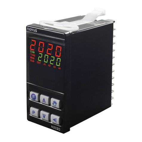
Novus N2020 User manual

Novus

Novus N2020 User manual

Novus N480D User manual

Novus

Novus N480D User manual

Novus N3000 User manual

Novus

Novus N3000 User manual

Novus N120 User manual

Novus

Novus N120 User manual

Novus N480D User manual

Novus

Novus N480D User manual

Novus N322 User manual

Novus

Novus N322 User manual

Novus XL6 User manual

Novus

Novus XL6 User manual

Novus N20K48 User manual

Novus

Novus N20K48 User manual

Novus N323RHT User manual

Novus

Novus N323RHT User manual

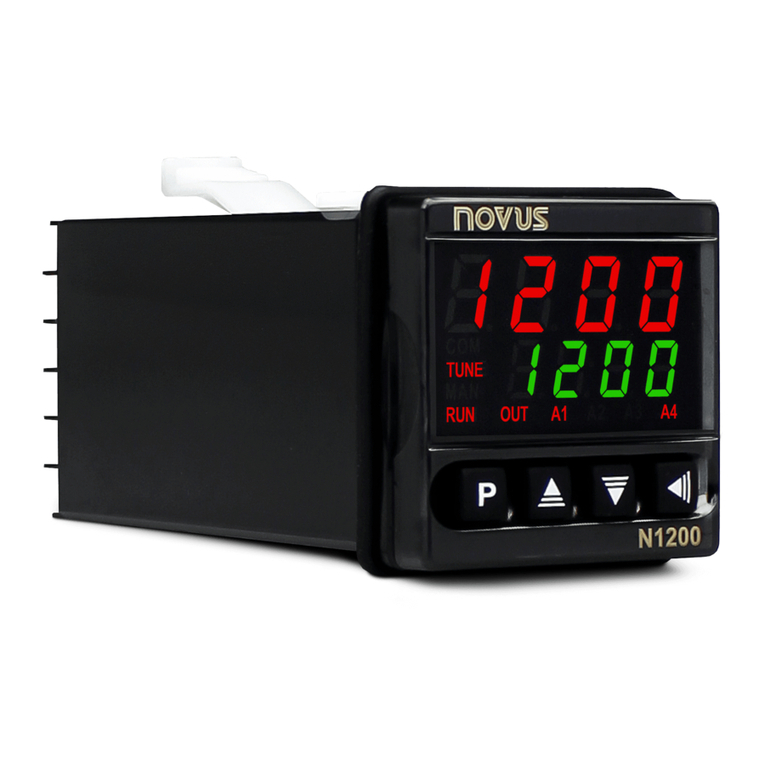
Novus N1200 User manual

Novus

Novus N1200 User manual

Novus N1030T User manual

Novus

Novus N1030T User manual

Novus N321R User manual

Novus

Novus N321R User manual

Novus PCW-3P-60 User manual

Novus

Novus PCW-3P-60 User manual

Novus N1100HC User manual

Novus

Novus N1100HC User manual

Novus N2000S User manual

Novus

Novus N2000S User manual

Novus N322RHT User manual

Novus

Novus N322RHT User manual

Novus N322S User manual

Novus

Novus N322S User manual

Novus N322T User manual

Novus

Novus N322T User manual

Novus N2000S User manual

Novus

Novus N2000S User manual

Novus N1040T User manual

Novus

Novus N1040T User manual

Novus N1030T User manual

Novus

Novus N1030T User manual

Popular Controllers manuals by other brands

Simrad RS100 quick start guide

Simrad

Simrad RS100 quick start guide

REXROTH IndraDrive M Project planning manual

REXROTH

REXROTH IndraDrive M Project planning manual

Ultra Products ULT40061 Specification sheet

Ultra Products

Ultra Products ULT40061 Specification sheet

Light Stream Controls Auto-Mate/DMX User instructions

Light Stream Controls

Light Stream Controls Auto-Mate/DMX User instructions

Allen-Bradley PLC-5 series user manual

Allen-Bradley

Allen-Bradley PLC-5 series user manual

Temcoline T30 SERIES user manual

Temcoline

Temcoline T30 SERIES user manual

vacuubrand CVC 3000 Instructions for use

vacuubrand

vacuubrand CVC 3000 Instructions for use

Meunier Technologies DICE ES Installation, operation and maintenance manual

Meunier Technologies

Meunier Technologies DICE ES Installation, operation and maintenance manual

STERIFLOW Mark 96A Series Installation & maintenance instructions

STERIFLOW

STERIFLOW Mark 96A Series Installation & maintenance instructions

IAI X-SEL Operation manual

IAI

IAI X-SEL Operation manual

Outback Power Systems MATE Installation and user manual

Outback Power Systems

Outback Power Systems MATE Installation and user manual

BFI Automation CFC 3000L Original operating instructions

BFI Automation

BFI Automation CFC 3000L Original operating instructions

Amerec Elite operating instructions

Amerec

Amerec Elite operating instructions

Velleman-Kit K8071 Illustrated assembly manual

Velleman-Kit

Velleman-Kit K8071 Illustrated assembly manual

spega ombra BST Technical manual

spega

spega ombra BST Technical manual

Datakom D-500 user manual

Datakom

Datakom D-500 user manual

Spa-Quip SPA Power 2000 user guide

Spa-Quip

Spa-Quip SPA Power 2000 user guide

Rodix FEEDER CUBE FC-40 Plus Series quick start guide

Rodix

Rodix FEEDER CUBE FC-40 Plus Series quick start guide

manuals.online logo
manuals.online logoBrands
  • About & Mission
  • Contact us
  • Privacy Policy
  • Terms and Conditions

Copyright 2025 Manuals.Online. All Rights Reserved.