TEMPERATURE CONTROLLER
N322S
OPERATING MANUAL - V1.9x G
Man 5001252
The N322S is a controller intended for solar water heating applications. It controls the water
circulation system based on the difference of temperature between the solar collector and
the storage tank (or swimming pool).
The instrument contains two NTC-type temperature sensors and two outputs: a control
output (output 1) for activating the water circulation pump and a booster output or support
output (output 2). It provides protections against overheating and freezing to the piping,
preventing damages to the system.
SPECIFICATIONS
INPUT SENSOR:
•Thermistor NTC, 10 kΩ@ 25 °C; Range: –50 to 120 °C (–58 to 248 °F); Accuracy: 0.6 °C
(1.1 °F);
Maximum error in the interchangeability of original NTC sensors: 0.75 °C (33.35 °F). This
error can be eliminated through the offset parameter of the equipment.
Note: For the NTC thermistor option, the sensor comes with the equipment. Its operating
range is limited to –30 to +105 °C (–222 to +221 °F). It has cable of 3 m in length, 2 x 0.5
mm², and can be extended up to 200 meters.
Measurement Resolution:.............................................................. 0.1 º from –19.9 to 119.9 º
..................................................................................... 1 ºC elsewhere
Note: The equipment keeps its precision all over the range, despite the lack of display
resolution in a part of the range does not allow its visualization.
Circulation Output (OUTPUT1): ...........................................................................Relay SPDT
.......................................................................1 HP 250 Vac / 1/3 HP 125 Vac (16 A Resistive)
Support Output (OUTPUT2): ........................................................Relay: 3A / 250 Vac, SPST
POWER SUPPLY: .......................................... 100 to 240 Vac/dc ±10 %
Optionally: .......................................... 12 to 30 Vdc/ac
Mains Frequency: ........................................50~60 Hz
Power Consumption: ............................................5 VA
DIMENSIONS: Width x Height x Depth: ............................................75 x 34 x 75 mm
Weight: .......................................................................................100 g
Panel: ................................................................................70 x 29 mm
ENVIRONMENT: Operating:.............................................0 to 40 °C (32 to 104 ºF)
Storage temperature: ......................... -20 a 60 °C (-4 to 140 ºF)
Relative humidity:............................ 20 to 85 % non-condensing
CASE: ..................................Polycarbonate UL94-2; Protection: Front panel: IP65, Box: IP42
....................................................................................................Suitable wiring: Up to 4.0 mm2
RS-485 digital communication; RTU MODBUS protocol (Optional)
Serial interface not isolated from input circuitry.
Serial interface isolated from power supply input, except in 24 V models.
INSTALLATION
It is important to follow the recommendations below:
•Signal wires should be installed in grounded conduits and away from power or contactor
wires.
•The instrument should have its own power supply wires that should not be shared with
electrical motors, coils, contactors, etc.
•Installing RC filters (47 R and 100 nF, series combination) is strongly recommended at
contactor coils or any other inductor.
•Use protection devices like circuit breakers and fuses.
ELECTRICAL WIRING
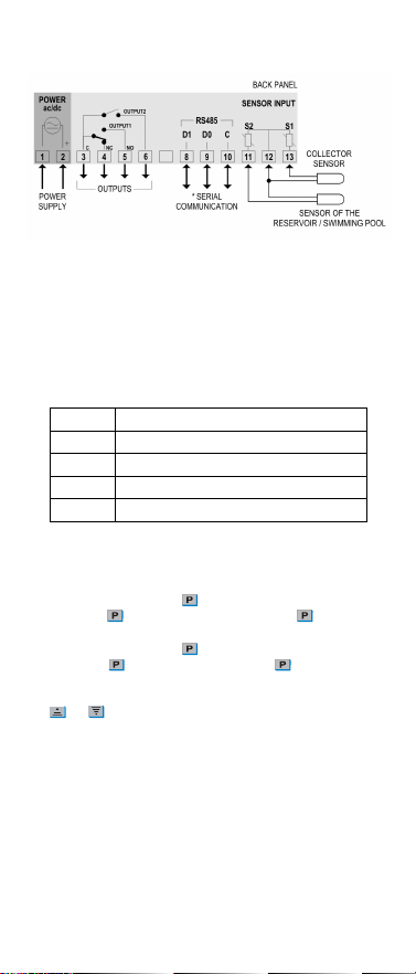
Fig. 1 below shows the controller connections to sensor, mains and outputs.
Fig. 1 – N322S terminals
OUTPUT1 is the Circulation Output.
OUTPUT2 is the Support Output.
* The serial communication interface is optional.
OPERATION
The N322S contains several parameters that need to be configured in order to determine
system behavior.
These configuration parameters are organized in groups, the so called parameter levels.
Level Function
0 Temperature Measurement
1 Setpoint Adjustment
2 Configuration
3 Calibration
Upon power-up, the N322S display shows for 1 second its firmware version. This information
is useful when consulting the factory.
Then, the temperatures of the sensors are displayed, according to the scheme defined in the
parameter “ind”. This is the parameter level 0(temperature measurement level).
For accessing the level 1, press the key for 2 seconds until the “D0n” parameter
appears. Release the key to remain on this level Pressing the key successively the
other parameters in this level are displayed.
For accessing the level 2, press the key for 4 seconds until the “unt” parameter
appears. Release the key to remain on this level. Press again to access the other
parameters of this level. After reaching the last parameter, the controller will return to the
temperature measurement level.
Use the and keys to alter a parameter value. The display alternates the parameters
prompts and their respective value.
Notes: 1 The configuration will be saved by the controller upon advancing to the next
parameter in a level.
2If no keypad activity is detected within 20 seconds, the controller saves the
current parameter value and returns to the measurement level.
Level 1 – Setpoint Adjustment
At this level, the display presents the setpoint parameters. They define the differential
temperatures values for the control. Use the and keys for setting the suitable
values.
Differential setpoint for activating the pump.
When the difference between T1 and T2 is higher
configured in
the pump will be turned on.
Max
value: 20 ºC.
Differential setpoint for deactivating the pump.
When the difference between T1 and T2 is lower than the value configured in
the pump will be turned off.
Adjustable between 1 ºC and
.
Setpoint for activating booster output.
Adjustable between
and
.
Level 2 – Programming Level
This level contains other configuration parameters that are needed for establishing a proper
system performance.
Unit
Temperature Unit – Defines the temperature unit to be displayed.
Temperature in degrees Celsius
Temperature in degrees Fahrenheit
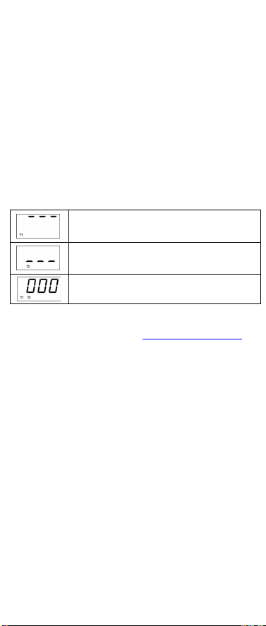
Indication
Temperature value exhibited on the display.
0
Temperature of the collectors (T1)
Temperature of the storage tank (T2)
Temperature difference between the sensors (T1 –T2)
Alternates the indication of (T1), (T2) and (T1-T2) at every 3s.
Ice
Setpoint for low temperature.
When the temperature in the solar collector is lower than the value here
configured, the pump is turned on, preventing the water from freezing in the
pipe system and causing damages to it.
Adjustable between
and
.
High
Temperature 1
Setpoint for high temperature (at collector).
When the temperature in the collector is above the value here configured,
the pump is turned off, avoiding the overheated water from damaging the
pipe system.
Adjustable between
and
.
High
Temperature 2
Setpoint for high temperature at S2 (storage tank).
When the temperature at the sensor S2 is above the value here configured,
the pump is turned off in order to avoid thermal discomfort.
This function is useful in swimming pool heating systems which do not use
dedicated third sensor.
Adjustable between
and
.
Action 1
Action type for booster output (
):
Reverse
Action Control. Good for heating. Turns on the booster
output when temperature is below SP1.
Direct Action Control. Good for cooling. Turns on the booster output
when temperature is higher than SP1.
Histeresis
Antifreezing temperature hysteresis of sensor S1 (
). In degrees.
Adjustable between 0.1 and 50.0 ºC
Histeresis 1
Overheating temperature hysteresis of sensor S1 (
). In degrees.
Adjustable between 0.1 and 50.0 ºC
Histeresis 2
Overheating temperature hysteresis of sensor S2 (
). In degrees.
Adjustable between 0.1 and 50.0 °C.