Novus NR2110-OG User manual

Users manual
NR2110-OG
Revision #:
J
Date:
3/17/17
Page #:
1 of 46
www.novuspower.com
User Manual Model NR2110-OG
Single Channel GPS Locked OCXO
Frequency Reference
All information provide herein is the proprietary property of Novus Power Products
L.L.C. The information included may be reproduced without the permission of Novus
Power Products L.L.C. with out prior approval for purpose of operating the equipment.

Users manual
NR2110-OG
Revision #:
J
Date:
3/17/17
Page #:
2 of 46
www.novuspower.com
Contents
1.0 Summary....................................................................................................................... 4
2.0 Controls and Indicators –Front Panel .......................................................................... 8
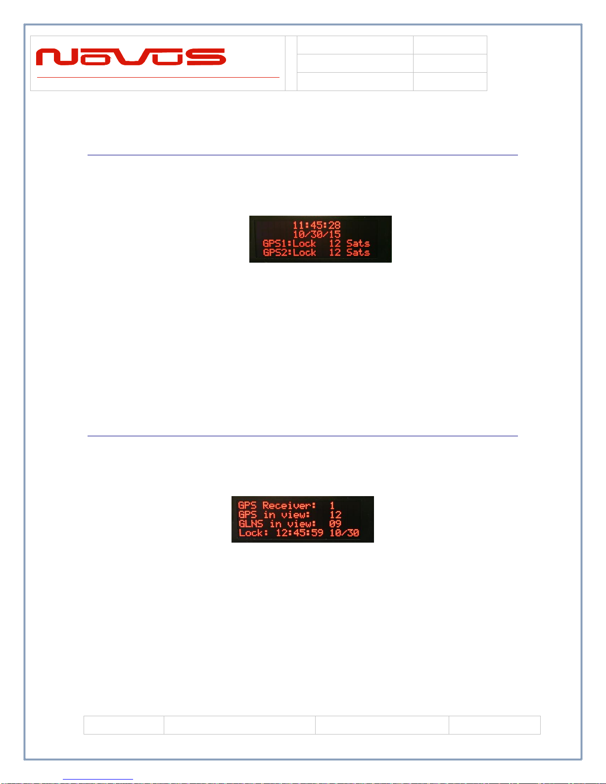
2.1 GNSS Status.............................................................................................................. 9
2.2 GNSS Detailed Status............................................................................................... 9
2.3 Channel Status ........................................................................................................ 10
2.4 Status LEDs ............................................................................................................ 11
2.5 Power Supply Status............................................................................................... 12
2.6 Alert Threshold....................................................................................................... 14
2.7 Latch Channel Value............................................................................................... 17
2.8 Save Configuration ................................................................................................. 17
2.9 Fault Status.............................................................................................................. 18
2.10 UTC Mode............................................................................................................ 19
2.11 GMT Offset........................................................................................................... 19
2.12 Power Switch........................................................................................................ 20
3.0 Rear Panel................................................................................................................... 21
3.1 Channel Ouput - BNC............................................................................................. 21
3.2 Antenna Input A/B - SMA...................................................................................... 21
3.3 DC Input.................................................................................................................. 21
3.4 AC Input.................................................................................................................. 22
3.5 RS232 DB9............................................................................................................. 22
3.6 Ethernet Port / Serial-Ethernet Bridge.................................................................... 23
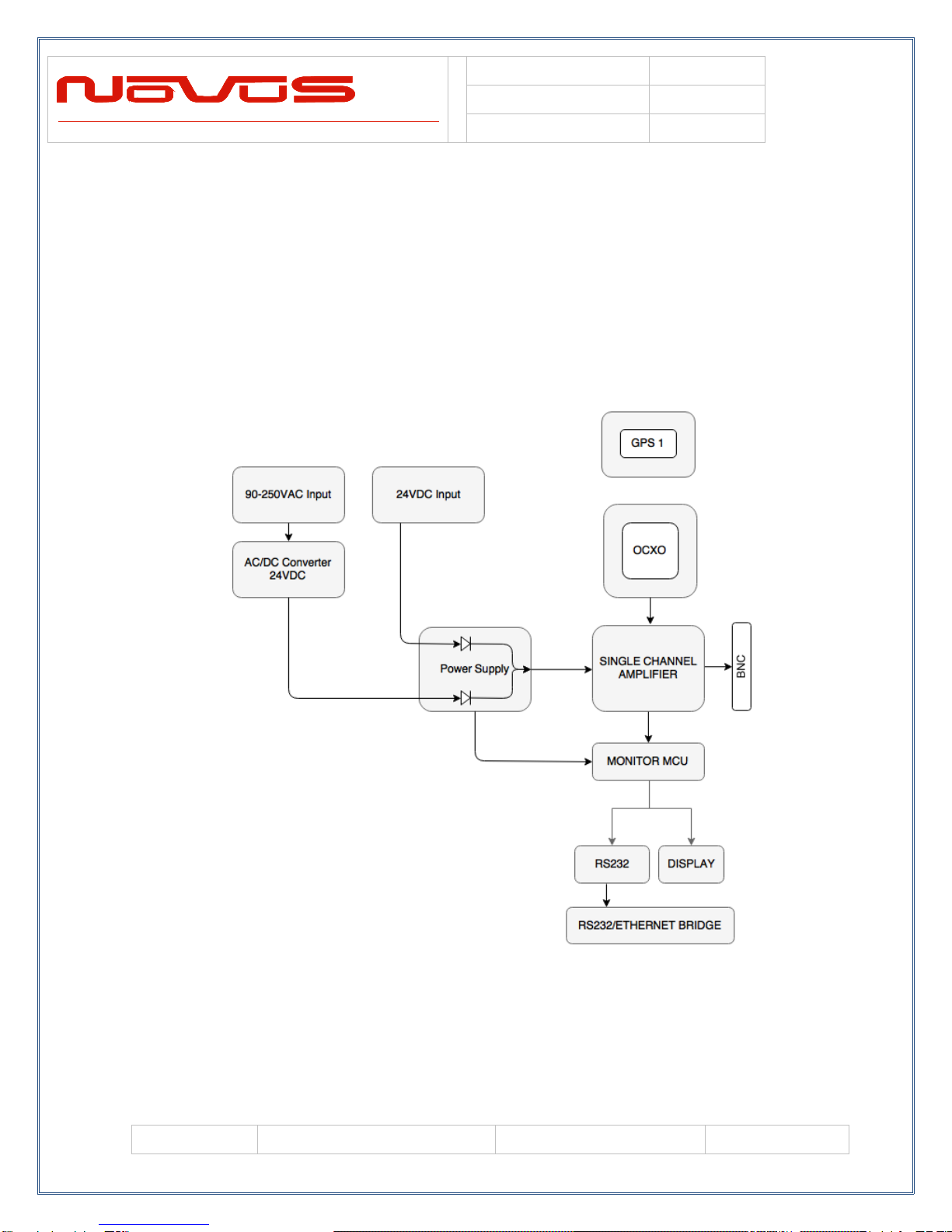
4.0 Functional Description................................................................................................ 24
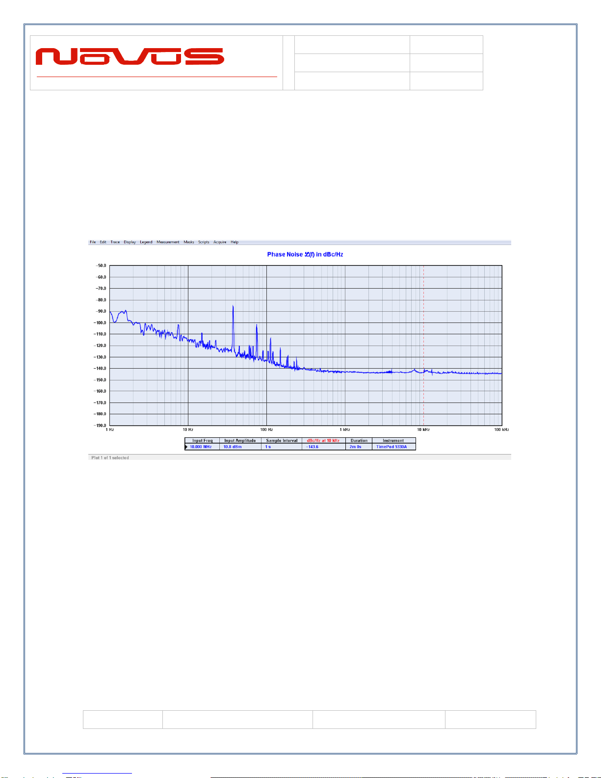
4.1 Phase Noise............................................................................................................. 25
4.2 Outputs.................................................................................................................... 26
4.3 Built in Test............................................................................................................. 27
4.4 Power Supplies........................................................................................................ 27
5.0 Crystal......................................................................................................................... 28
6.0 Calibration................................................................................................................... 34
7.0 Programming Guide (RS232 Port: Front and Rear) ................................................... 35
7.1 RS232 Commands .................................................................................................. 36
7.2 Status String ($GPNVS,1) Fault Bytes................................................................... 39
7.3 Status String ($GPNVS,2) Channel Values 1-8 ..................................................... 40
7.4 Status String ($GPNVS,3) Power Supply Values.................................................. 41
7.5 Status String ($GPNVS,4) Channel Values 9-16 ................................................... 42
8.0 Technical Specification............................................................................................... 43
8.1 Performance............................................................................................................ 43
8.2 Environmental and Mechanical .............................................................................. 43
9.0 LIMITED HARDWARE WARRANTY.................................................................... 44
10.0 Appendix: GNSS Command Reference.................................................................... 46

Users manual
NR2110-OG
Revision #:
J
Date:
3/17/17
Page #:
3 of 46
www.novuspower.com

Users manual
NR2110-OG
Revision #:
J
Date:
3/17/17
Page #:
4 of 46
www.novuspower.com
1.0 Summary
The NR2110 is a Single Channel precision GNSS/GPS locked 10MHz frequency
reference. The amplifier is a low phase noise design to preserve the integrity of the
reference signal. All outputs are transient and fault protected.
The unit features auto-calibration, which ensures the most recent OCXO compensation
coefficients are stored in non-volatile memory. The compensation values eliminate drift
due to aging and/or temperature, and are stored and applied to the OCXO during loss of
GPS lock conditions. These coefficients are updated after two hours of continuous GPS
locked state. This effectively eliminates long-term OCXO changes.
Excellent aging characteristics are achieved through the use of intrinsically low jitter
overtone SC cut crystals in a temperature controlled oven. There is one 10MHz output
on the rear panel (BNC) connector. Low phase noise is achieved by the inherent crystal
characteristics and appropriate design techniques for noise mitigation.
Units can be customized to any number of channels, can be changed to PPS output, or
can be customized to be sine or square wave output, etc.
Typical Phase Noise performance:
Offset Frequency, Typical
Offset (Hz)
Standard (dBc/Hz)
10
-110
100
-135
1k
-145

Users manual
NR2110-OG
Revision #:
J
Date:
3/17/17
Page #:
5 of 46
www.novuspower.com
The NR2110-OG delivers a low phase noise curve, which can be seen in the sample
production test below.
NR2110-OG Phase Noise Measurement

Users manual
NR2110-OG
Revision #:
J
Date:
3/17/17
Page #:
6 of 46
www.novuspower.com
The unit features extensive reporting via the rear panel RS232 port. Equipment
status, output voltage on each channel and redundancy status. By being able to
monitor the output voltage, the user can detect cabling issues that cause an
impedance change and replace cabling before it completely fails. Reporting is also
easily accessible via the front panel display.

Users manual
NR2110-OG
Revision #:
J
Date:
3/17/17
Page #:
7 of 46
www.novuspower.com
Nominal power is global AC power but a DC power option can be ordered that
acts as the back-up power supply. Nominally 24 vdc, this port is used for power
when AC power fails. Switching between power sources is automatic and there is
no transient power outage at the equipment level. The primary power supply is
followed by low noise linear converters assemblies. There will be one in a non-
redundant configuration. Each power supply supplies one of the amplifier
assemblies.
To enhance versatility, the unit features a flexible output stage. Each output
amplifier can be configured as a linear amplifier, CMOS output with ±20 ma
drive or a very low impedance sourcing output of over 100ma (ideal for driving
pulsed outputs in to 50 Ohms). This must be specified at the time of ordering.

Users manual
NR2110-OG
Revision #:
J
Date:
3/17/17
Page #:
8 of 46
www.novuspower.com
2.0 Controls and Indicators –Front Panel
This section describes the functionality of the front panel controls and indicators.
Two buttons above the status LEDs provide navigation through the menus.
In general, the NEXT button advances through the menus to the next screen,
while the SELECT button chooses between the available values on a menu.
Menus that allow selectable adjustments are the Input Threshold, Alert Threshold,
and the Attenuation setting. To adjust these values from the front panel, hold
down both buttons for two seconds, until the value begins to flash. To leave the
menu with the new value, hold down both buttons until the value is solid.
Screen Saver: After 1 hour, the OLED Display will turn off, unless activated by a
fault condition, or by a user input, such as pressing the NEXT or SELECT
buttons.

Users manual
NR2110-OG
Revision #:
J
Date:
3/17/17
Page #:
9 of 46
www.novuspower.com
2.1 GNSS Status
On power up, the NR2110-OG will display the Time and Date as well as the
current status of the GNSS receiver. If the unit is dual time based, both receivers
will have status displayed.
GNSS: The GNSS status indication allows the user to observe the Lock status of
the receivers, and the number of GNSS satellites in view. Before GNSS lock is
acquired, the status will be “Tracking” and the number of satellites will be shown.
When GNSS lock is acquired, the status will change to “Lock.”
Time and Date: The time zone will be UTC by default, but the hour can be offset
to the local time in the UTC Offset menu. Changes to UTC offset and Hour mode
will be reflected on this screen, but will not change the NMEA output data.
2.2 GNSS Detailed Status
The GNSS Status Menu gives the user a quick reference for the quality of the
GNSS satellite signal and length of time that each receiver has been locked.
To toggle between each receiver, press the SELECT button. The screen will
display which receiver status is being viewed.
The user can then see number of GPS satellites in view, number of GLONASS
satellites in view, and the UTC time and date that lock occurred on the selected
receiver.

Users manual
NR2110-OG
Revision #:
J
Date:
3/17/17
Page #:
10 of 46
www.novuspower.com
2.3 Channel Status
The Channel Status can be determined by reading the actual RMS value on the
output of each stage. This is compared to a threshold limit that is set by the user as
a percentage variation from a saved value. The default variation value is set at
±25% percent from the current state of the amplifier, and is user programmable in
5% increments from ±10% to ±60%.
The range of acceptable Channel Amplitude can be narrowed around a connected
balanced line, such that a Channel Status below the Alert Threshold indicates a
shorted line, while a Channel Status above the Alert Threshold window indicates
a potential disconnected cable.
The threshold value at which a channel alert is triggered can be programmed on
the Alert Threshold screen, or programmed via the RS232 port. Once set, the unit
would continue to monitor each channel and a deviation beyond the set limits
would be reported as a failure on the front panel and via RS232.
The Channel Status feature can quickly detect a cabling failure. Any change in
the load impedance will change the output voltage with respect to the divider
formed by the output impedance of the amplifier and the load impedance. Failing
cables and connectors can be detected early.
The current threshold limits are displayed in addition to the actual measured
value. These values reflect the percentage threshold defined in the Alert
Threshold settings. If the output value is too low to give a valid reading. The
display will read “LOW.”
The status is displayed on the front panel and is accessible over the RS232 serial
bus via DB9.

Users manual
NR2110-OG
Revision #:
J
Date:
3/17/17
Page #:
11 of 46
www.novuspower.com
2.4 Status LEDs
There are three status LEDs which provide a quick indication of valid unit
operation.
Alert LED: The Alert LED will illuminate flashing red to indicate A GNSS
failure or a power supply failure. The Alert LED will not flash RED if any valid
input signal is present.
Oven LED (OCXO option only): The Oven LED will illuminate red to indicate
an Oven Failure.
Fault LED: The Fault LED will illuminate flashing red to indicate a Channel
Fault, when any single channel is outside the user defined threshold.

Users manual
NR2110-OG
Revision #:
J
Date:
3/17/17
Page #:
12 of 46
www.novuspower.com
2.5 Power Supply Status
The Power Supply Status screen provides DC voltage values of the two available
power supply sources. The 90-250V AC input is internally connected to an
internal 24V AC-DC convertor which powers the internal supplies with 24V.
This is diode connected with the external 24V DC input, which can be used in
addition to, or in place of, the AC input.
The values of both DC supplies are measured internally to validate connections.
The measured values of the AC/DC convertor and the DC input are reported in
the third and fourth fields of the second $GPNVS status string.
For details on the status strings, see Programmer’s Guide.
In addition to direct value measurements, each redundant system has a Power
Supply Status byte which is reported in the third $GPNVS status string, in the
seventh and eighth fields respectively.
Any measurement of the power supply which results in an alert condition will be
reported in the power supply status byte.
0x80 = External AC not connected.
0x40 = External DC not connected.

Users manual
NR2110-OG
Revision #:
J
Date:
3/17/17
Page #:
13 of 46
www.novuspower.com
If the optional external DC Power supply is requested, redundant power supplies
will operate on either the AC input or DC input, and function independently. All
functionality and reporting for an individual power supply and amplifier is
independent of its redundant copy.
If a communications failure is reported, the backup system will automatically
switch to the redundant system.

Users manual
NR2110-OG
Revision #:
J
Date:
3/17/17
Page #:
14 of 46
www.novuspower.com
2.6 Alert Threshold
The Alert Threshold screen allows the user to adjust the tolerance from the
Reference Voltage which, if exceeded in either direction, the output channel will
report a fault status. The default threshold value is set at ±25% percent from the
current state of the amplifier, and is user programmable in 5% increments, from
±10% to ±60%.
The output channel has a Reference Voltage which can be set by latching the
channel’s current value in the Latch Channel Average Screen. The output
reference voltage can be set individually by writing the value serially with the
$SET command. After saving the current configuration on a channel, any
subsequent deviation on that channel which exceeds the Alert Threshold
percentage will trigger an alert.
Steps to ensure correct Alert configuration:
1. Connect distribution cabling to the 10MHz output.
2. Set Alert Threshold to desired range.
3. Save current channel voltage with the Latch Channel Values Screen.
4. Save current settings on the Save Configuration screen.

Users manual
NR2110-OG
Revision #:
J
Date:
3/17/17
Page #:
15 of 46
www.novuspower.com
The Alert Threshold can be optimized so that a channel short or an impedance
change will cause an Alert.

Users manual
NR2110-OG
Revision #:
J
Date:
3/17/17
Page #:
16 of 46
www.novuspower.com
Example:
The output of channel 1 is connected to a high impedance input and reports
1.25Vrms at the output.
Alert threshold is set to +/-20%.
The current state is saved in the Save Configuration screen.
The Channel 1 alert will report when:
-The Channel 1 output is higher than 1.50Vrms
-The Channel 1 output is lower than 1.00Vrms
To adjust the Alert Threshold from the front panel, hold the NEXT and SELECT
buttons down simultaneously for two seconds. The percentage value will begin
flashing. To increase the value, press the SELECT button. To decrease the value,
press the NEXT button.
When the desired value is reached, press the NEXT and SELECT button
simultaneously to leave the settings mode.
The Alert Threshold settings can be modified via the RS232 serial port with the
$FLTTHR command.
For details on the Alert Threshold, see Programmer’s Guide.

Users manual
NR2110-OG
Revision #:
J
Date:
3/17/17
Page #:
17 of 46
www.novuspower.com
2.7 Latch Channel Value
The Latch Channel Values Screen allows the user to save the current channel
output value for use as the Reference Value for Alert settings.
A channel Alert is triggered when the channel output voltage exceeds or falls
below a percentage of the Reference Value. This Reference value is 1.10Vrms as
a default, but can be set by the user.
There are two ways to set the Reference Voltage. The RS232 serial port allows
for setting an individual channel’s reference voltage with the $SET command.
The user can also use the Latch Channel Values to take a snapshot of all current
outputs, and use these as the reference values.
2.8 Save Configuration
The Save Configuration screen allows the user to save the current settings for
Alert Threshold, Input Threshold, Attenuation, Input Select, Reference Voltage
and any other settings that have been modified via the RS232 port.
To save the current settings, press the SELECT button twice.
The Save Configuration action is equivalent to the $SAVEFL command on the
serial port.

Users manual
NR2110-OG
Revision #:
J
Date:
3/17/17
Page #:
18 of 46
www.novuspower.com
2.9 Fault Status
The Fault Status screen allows a quick overview of any Channel faults from the
front panel.
Press SELECT to advance to the System Fault Screen.
The System Fault Screen indicates any failures in the primary system or the
redundant backup system. All internal power supplies are monitored (24V, +8V,
-8V, 5V) on both the primary and backup systems. A failure on one of these
supplies will be indicated with a “PS FAIL” fail warning for either system. A
communication failure would be indicated by a “Com FAIL” indicator. Either of
these fault statuses will result in the change of the primary to the backup system.
The individual statuses of the internal power supplies are also available via the
RS232 serial port.
The presence of a valid DC input voltage is indicated on this screen, as well as a
valid AC power input. If either of these supplies are not present, a “FL”
indication will be shown next to the appropriate input.

Users manual
NR2110-OG
Revision #:
J
Date:
3/17/17
Page #:
19 of 46
www.novuspower.com
2.10 UTC Mode
The user can select how the time is displayed on the screen by choosing between
three formats: UTC, 24 hour mode, or 12 hour mode. Toggle through the modes
by pressing the SELECT button.
If 24 hour mode or 12 hour mode is chosen, the GMT offset will be applied to the
displayed time. If GMT mode is selected, no offset will be applied to the
displayed time.
2.11 GMT Offset
With 24 hour mode or 12 hour mode, the user can choose to align the displayed
hour with their current time zone. Using the SELECT button, toggle to the
desired offset. The offset will decrement through the 24 hour period, from UTC-
11 to UTC +12, etc.
Adjusting the GMT offset will affect the displayed date. As the hour moves
across the International Dateline, the displayed date will reflect the date in the
selected time zone, and not necessarily the GMT date.

Users manual
NR2110-OG
Revision #:
J
Date:
3/17/17
Page #:
20 of 46
www.novuspower.com
2.12 Power Switch
The front panel Power Switch controls AC Power input to the unit. If the
optional DC input is provided with 24V, or a valid DC supply, the unit will
operate. In other words, if the front panel switch will not remove power if the
optional DC input is powered.
The AC and DC input option provides a redundant and automatic backup source
in the case of failure of either input.
Table of contents
Other Novus Receiver manuals

Novus
Novus NVPT-414V-II User manual

Novus
Novus PICOPOD NR7000 User manual

Novus
Novus N4430-O-G User manual

Novus
Novus NVPT-A122VRH User manual

Novus
Novus NR3700-O/G User manual

Novus
Novus NR2310-O/G User manual

Novus
Novus NVPT-A121VT User manual

Novus
Novus NVPT-A151VR-HD User manual

Novus
Novus NR2310D-O/G User manual

Novus
Novus NVPT-111VT User manual