Novus NR2310D-O/G User manual

USERS GUIDE
NR2310D-O/G
REVISION
M
DATE
071720
Page #:
1
www.novuspower.com
NR2310D-O/G
10 Channel GNSS Locked Frequency Reference with RS232,
Display and optional Ethernet-SNMP
All information provided herein is the proprietary property of Novus Power Products
LLC. The information included may be reproduced without the permission or prior
approval of Novus Power Products LLC for the purpose of operating the equipment.

USERS GUIDE
NR2310D-O/G
REVISION
M
DATE
071720
Page #:
2
www.novuspower.com
Summary ....................................................................................................................4
Summary of Configuration Options..........................................................................4
The Time Base............................................................................................................5
Temperature Compensated Crystal Oscillator (TCXO)............................................5
Oven-Controlled Crystal Oscillator ..........................................................................6
Atomic Oscillator.........................................................................................................7
GNSS/GPS Disciplined Oscillator (GPSDO)...............................................................8
Dual-Time Base Frequency Verification (option).......................................................10
GNSS Receiver.........................................................................................................11
Sensitivity..............................................................................................................11
TTFF (Time to First Fix) ........................................................................................11
PPS ..........................................................................................................................14
PPS Availability.....................................................................................................14
Cable Delays.........................................................................................................15
Pulse Width...........................................................................................................15
Factory Default Settings........................................................................................15
Output Drive..............................................................................................................16
PPS Accuracy.......................................................................................................16
PPS Holdover .......................................................................................................16
NMEA - RS232 .........................................................................................................18
Base Unit Block Diagram..........................................................................................21
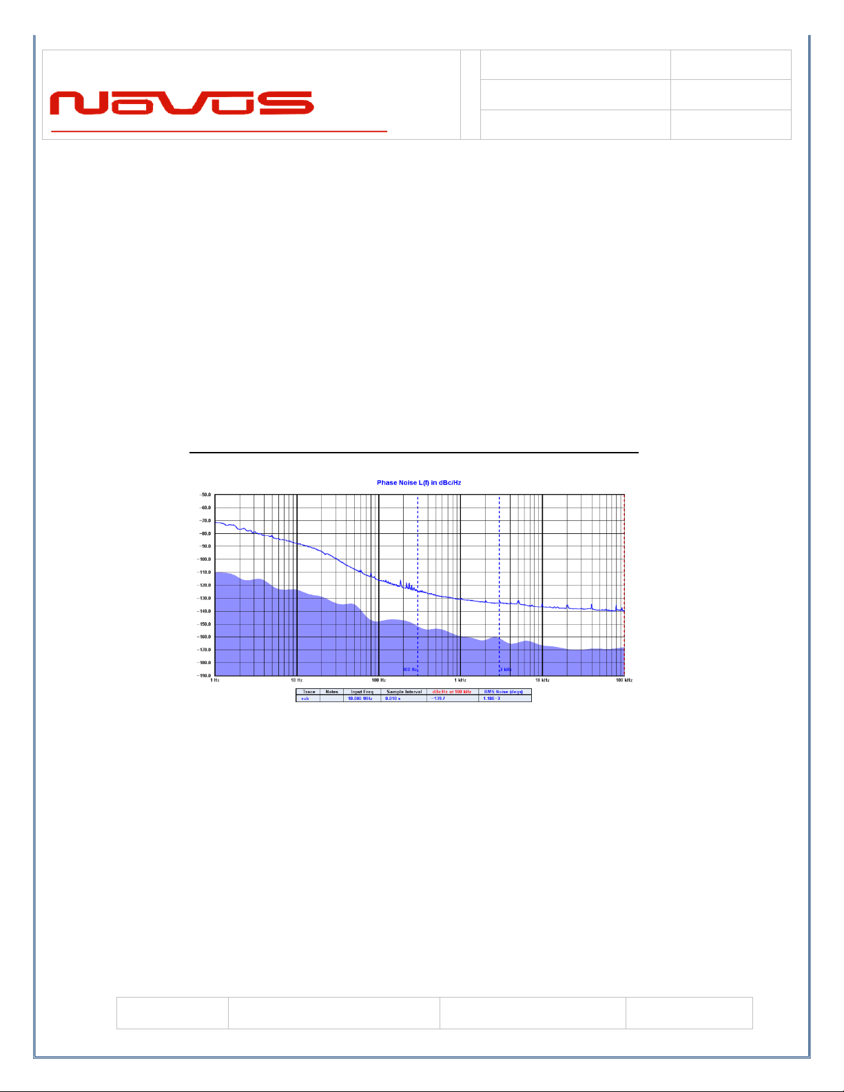
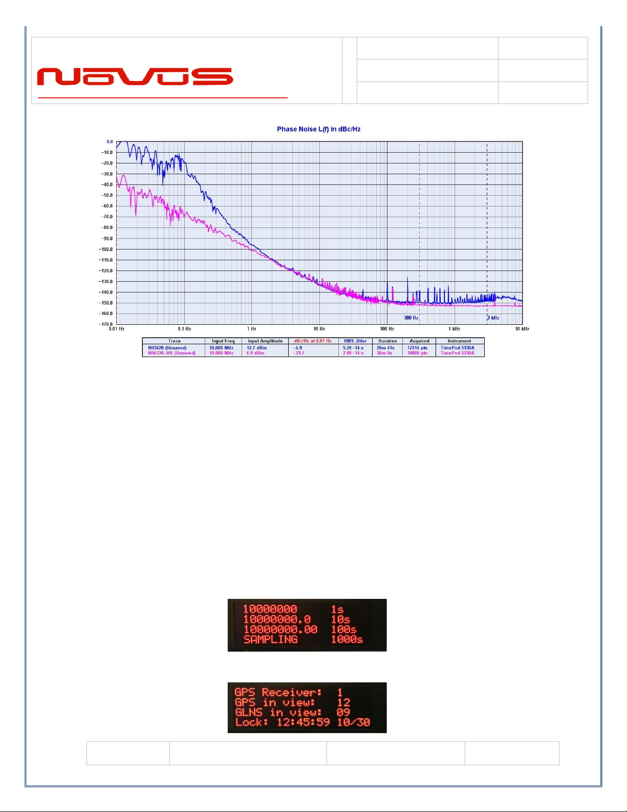
Phase Noise Performance........................................................................................23
Controls and indicators .............................................................................................23
Channel Status- Front panel LED’s .......................................................................23
Oven- LED front Panel..........................................................................................24
Digital Display (Optional).......................................................................................24
Time/Date/Lock Status..........................................................................................24
GNSS/GPS Status................................................................................................25
UTC Mode.............................................................................................................25
GMT offset............................................................................................................26
Channel Status .....................................................................................................26
Next and Select Buttons........................................................................................26
RS232 NMEA / Alert –DB9 Male (Optional).........................................................27
Rear Panel - Outputs ................................................................................................28
Channel 1 through 10 output connectors –BNC or SMA.......................................28
PPS –SMA (with GPS locking option) ..................................................................28
Alert –BNC-SMA..................................................................................................29
Power In................................................................................................................29
Antenna Connection (with GNSS option only).......................................................29
Functional Description (Base NR2310D-OG)............................................................31
Outputs.................................................................................................................31

USERS GUIDE
NR2310D-O/G
REVISION
M
DATE
071720
Page #:
3
www.novuspower.com
Built-in Test...............................................................................................................31
Power Supplies.....................................................................................................31
Specifications............................................................................................................33
Technical Specifications........................................................................................33
Environmental and Mechanical .............................................................................34
LIMITED HARDWARE WARRANTY.........................................................................35

USERS GUIDE
NR2310D-O/G
REVISION
M
DATE
071720
Page #:
4
www.novuspower.com
Summary
Summary of Configuration Options
A multi-channel based reference for very demanding telecommunications,
precision scientific research and calibration. The multi-use platform can be
configured with several performance options:
1. a range of stability options
2. high reliability (full redundancy is offered with the new NR2300 line)
3. display and user interface
4. local and remote monitoring via RS232
5. Ethernet port to allow remote monitoring and control

USERS GUIDE
NR2310D-O/G
REVISION
M
DATE
071720
Page #:
5
www.novuspower.com
The Time Base
Novus crystal-based frequency reference products are based upon either
TCXO or OCXO technology. Temperature compensated crystal oscillators will
normally use an AT cut crystal and electronically compensate the device with
temperature. An OCXO device uses a SC (stress compensated) crystal and
the part is held at a fixed temperature to minimize temperature drift.
Temperature Compensated Crystal Oscillator (TCXO)
The TCXO implementation results in a temperature stable reference in the
single digit parts per million.
Comparison of AT vs SC Cut Crystal
Over a broad temperature range, an AT cut crystal performs very well and
much easier to compensate electronically. It is also a simpler crystal to

USERS GUIDE
NR2310D-O/G
REVISION
M
DATE
071720
Page #:
6
www.novuspower.com
manufacture than a SC cut device. For applications where a stability of a few
ppm is acceptable, a TCXO can be a cost-effective alternative.
The SC cut results in a much higher Q device and achieves much lower phase
noise than the AT cut. The device is also more sensitive to pressure and
temperature variation and is therefore mounted in a temperature-controlled
hermetic chamber.
Oven-Controlled Crystal Oscillator
An OCXO device affords a reference that is almost two orders of magnitude
more stable than the TCXO. OCXO oven temperature is in the range of 90°C.
The devices heat-up and become stable within ~ 5 minutes.
OCXO Frequency Error from Cold Start
Typical OCXO
-2.00E+02
-1.50E+02
-1.00E+02
-5.00E+01
0.00E+00
5.00E+01
1
13
25
37
49
61
73
85
97
109
121
133
145
157
169
181
193
205
217
229
241
Error in Hz
Time in seconds
Frequency Error 1 to 250 seconds

USERS GUIDE
NR2310D-O/G
REVISION
M
DATE
071720
Page #:
7
www.novuspower.com
Atomic Oscillator
Another type of time base is an atomic reference. These devices use a change
in atomic state of an isotope of Cesium or Rubidium for stability. Instead of a
stability of ±50 ppb/year for a typical OCXO - stability of ±1 ppb/year is very
common.
Atomic sources are very complex and while a very stable source, phase noise
performance may not be acceptable for many applications.
RUBIDIUM SOURCE TYPICAL PHASE NOISE PERFORMANCE
For applications requiring the stability of an atomic source but also requiring
low phase noise, a low phase noise OCXO is disciplined to an atomic source.
The phase noise for the NR2110-R/O has phase noise improved by well over
20 dB by this technique.

USERS GUIDE
NR2310D-O/G
REVISION
M
DATE
071720
Page #:
8
www.novuspower.com
RUBIDIUM SOURCE WITH OCXO –TYPICAL PHASE NOISE PERFORMANCE
GNSS/GPS Disciplined Oscillator (GPSDO)
When the stability of an atomic or crystal source is not sufficient a GNSS
disciplined source is an option. A GNSS receiver is installed and timing
information from the GNSS is used to discipline the timing device. Timing
accuracy to a ~E-12 is readily achievable.
The GNSS is used to provide timing for a control loop that modulates the
OCXO to bring it in alignment with the PPS timing information. A GNSS timing
source has considerable short-term instability due to the numerous radio
effects - multi-path, signal weakness, etc. In order to develop a stable
reference, the GNSS timing waveform is used to discipline a low noise source
with a Kalman Filter. A good example of the improved jitter performance of a
Kalman Filter is shown below:

USERS GUIDE
NR2310D-O/G
REVISION
M
DATE
071720
Page #:
9
www.novuspower.com
KALMAN FILTER PERFORMANCE
The control loop that modulates the OCXO frequency can become very
complex. In its simplest form, the GNSS clock is used to create a DDS that is
then used in what is basically a PLL to develop an error signal to correct the
OCXO frequency. However, the GNSS synthesized clock is modulated by the
radio transmission artifacts which have very low frequency content. Designing
a loop to deal with sub-1 Hz noise is a challenge.
More advanced loops take on the task of controlling the OCXO frequency with
the PPS with sophisticated signal processing techniques. The improvement in
performance for low-frequency content can be dramatic for close-in phase
noise. The following phase noise curve is an example of a conventional PLL
structure versus a signal processing loop. Close-in phase noise is reduced by
more 20 dB.

USERS GUIDE
NR2310D-O/G
REVISION
M
DATE
071720
Page #:
10
www.novuspower.com
.
Dual-Time Base Frequency Verification (option)
GNSS locked references find application in laboratories where the integrity of
the source must be beyond question. With a GNSS locked source, there could
be a source malfunction that could cause the source to be in error. To be able
to detect a problem, the dual-time base literally adds a second GNSS receiver
and an embedded frequency counter to measure the accuracy of the primary
reference. In some applications, a second antenna is installed, or a splitter can
be used to drive both time-base references from a single antenna.
The average frequency of each gate can be monitored at this screen, allowing
the user to see the most recent sample from the 1, 10, and 100 second gate.

USERS GUIDE
NR2310D-O/G
REVISION
M
DATE
071720
Page #:
11
www.novuspower.com
GNSS Receiver
The 26 channel GNSS receiver and companion elements generate the GNSS
PPS and NMEA serial link. The serial link conforms to NMEA 0183 protocol.
GPS, GLONASS, QZSS, SBAS, Active Anti-Jamming and Advanced Multipath
Mitigation Functions.
Supports concurrent GPS, GLONASS, SBAS and QZSS. Galileo Ready.
Sensitivity
GPS
Tracking: -161 dBm
Hot Start: -161 dBm
Warm Start: -147 dBm
Cold Start: -147 dBm
Reacquisition: -161 dBm
GLONASS
Tracking: -157 dBm
Hot Start: -157 dBm
Warm Start: -143 dBm
Cold Start: -143 dBm
Reacquisition: -157 dBm
TTFF (Time to First Fix)
Hot Start: <5 sec (@-130 dBm)
Warm Start: 35 sec (@-130 dBm)
Cold Start: 40 sec (@-130 dBm)
・Active Anti-Jamming
・Advanced Multipath Mitigation
The receiver needs at least four satellite vehicles (SVs) visible to obtain an
accurate 3-D position fix. When travelling in a valley, or built-up area, or under
heavy tree cover, you will experience difficulty acquiring and maintaining a
coherent satellite lock. Complete satellite lock may be lost, or only enough
satellites (3) tracked to be able to compute a 2-D position fix, or a poor 3D fix
due to insufficient satellite geometry (i.e. poor DOP). It may not be possible to

USERS GUIDE
NR2310D-O/G
REVISION
M
DATE
071720
Page #:
12
www.novuspower.com
update a position fix inside a building or beneath a bridge. The receiver can
operate in 2-D mode if it goes down to seeing only three satellites by assuming
its height remains constant. But this assumption can lead to very large errors,
especially when a change in height does occur. A 2-D position fix is not
considered a good or accurate fix; it is simply “better than nothing”.
The receiver’s antenna must have a clear view of the sky to acquire satellite
lock. Remember, it is the location of the antenna that will be given as the
position fix. If the antenna is mounted on a vehicle, survey pole, or backpack,
allowance for this must be made when using the solution. The GNSS receiver
provides power for the LNA in the antenna. The unit was designed to provide
3.5 Vdc < 40 mA of current.
To measure the range from the satellite to the receiver, two criteria are
required: signal transmission time and signal reception time. All GPS satellites
have several atomic clocks that keep precise time and are used to time-tag the
message (i.e. code the transmission time onto the signal) and to control the
transmission sequence of the coded signal. The receiver has an internal clock
to precisely identify the arrival time of the signal. Transit speed of the signal is
a known constant (the speed of light), therefore: time x speed of light =
distance.
Once the receiver calculates the range to a satellite, it knows that it lies
somewhere on an imaginary sphere whose radius is equal to this range. If a
second satellite is then found, a second sphere can again be calculated from
this range information. The receiver will now know that it lies somewhere on
the circle of points produced where these two spheres intersect.
When a third satellite is detected and a range determined, a third sphere
intersects the area formed by the other two. This intersection occurs at just two
points. A fourth satellite is then used to synchronize the receiver clock to the
satellite clocks.

USERS GUIDE
NR2310D-O/G
REVISION
M
DATE
071720
Page #:
13
www.novuspower.com
In practice, just four satellite measurements are sufficient for the receiver to
determine a position, as one of the two points will be totally unreasonable
(possibly many kilometers out into space). This assumes the satellite and
receiver timing to be identical. In reality, when the receiver compares the
incoming signal with its own internal copy of the code and clock, the two will no
longer be synchronized. Timing error in the satellite clocks, the receiver, and
other anomalies mean that the measurement of the signal transit time is in
error. This, effectively, is a constant for all satellites since each measurement
is made simultaneously on parallel tracking channels. Because of this, the
resulting ranges calculated are known as “pseudo-ranges”.
To overcome these errors, the receiver then matches or “skews” its own code
to become synchronous with the satellite signal. This is repeated for all
satellites in turn, thus measuring the relative transit times of individual signals.
By accurately knowing all satellite positions and measuring the signal transit
times, the user’s position can be accurately determined.

USERS GUIDE
NR2310D-O/G
REVISION
M
DATE
071720
Page #:
14
www.novuspower.com
PPS
The PPS (one Pulse Per Second) relationship with the NMEA data is shown
below:
The serial data timing is for the next rising edge of the PPS pulse.
There are a number of attributes for the PPS that can be controlled via the
RS232 port with the radio. However ,when the Rubidium option is chosen, the
PPS generated by the Rubidium is used and can’t be programmed.
PPS Availability
There is a TCXO that is used to maintain the PPS in the event of GNSS loss.
The radio can be programmed to either have the PPS stop when GNSS lock
occurs or continue with the stability of the internal TCXO. The TCXO has a
stability shown below.

USERS GUIDE
NR2310D-O/G
REVISION
M
DATE
071720
Page #:
15
www.novuspower.com
For applications requiring a more stable PPS –a source such as an OCXO or
atomic reference should be considered. The PPS can also be enabled or
disabled based upon a calculated accuracy.
Cable Delays
The unit can be programmed to compensate for PPS errors due to cable
length. A compensation factor of +/-100000 ns can be used.
Pulse Width
The pulse width can be programmed from 1 to 500ms.
Factory Default Settings
PPS on when estimated accuracy is within 1 usec.
Pulse width is 100ms.

USERS GUIDE
NR2310D-O/G
REVISION
M
DATE
071720
Page #:
16
www.novuspower.com
Output Drive
Connecting a PPS to a load is problematic at best. Connecting a 10 MHz sine
to many devices is routine and the understanding of matching load and cable
impedances is well understood. The problems arise when connecting a PPS to
a load in the same manner as a simple sine wave. A CMOS device will not
drive a 50 Ohm load to required voltage levels. A PPS pulse with a rise and fall
time of 5 ns is a much greater problem for a cable than a simple sine wave at
10 MHz. The 5ns edge requires almost an order of magnitude more bandwidth
than a 10 MHz signal even though most consider the PPS to be a 1 Hz signal.
Novus PPS drive is configurable at the factory for 5 or 3.3 VDC CMOS logic
levels with drive capability to handle up to a 50 Ohm load. The PPS drive must
be established at the time ordering.
PPS Accuracy
15ns(1σ) (@-130 dBm)
50ns(1σ) (@-150 dBm)
The nominal accuracy of a PPS signal that is directly from the radio is on the
order of 25 ns rms. The signal will also have ~5 ns of jitter. The jitter is due to
the characteristics of the transmission channel - multi-path and other radio
effects. The long-term accuracy of the PPS is excellent. There are numerous
reference documents produced by NIST that define accuracy.
For those applications where the 5 ns of jitter is unacceptable, there is a more
stable source. To solve the jitter problem, a stable oscillator is locked to the
PPS and the output of the oscillator is then counted down to 1 Hz to have jitter
level that is dominated by the oscillator and associated electronics. Normally, a
Kalman Filter is used to discipline the oscillator and the resulting performance
is a function of the design and the quality of the oscillator. PPS jitter can be
improved from the 5 ns range to less than 200 ps.
PPS Holdover
PPS holdover is concerned with the stability of the PPS when GNSS lock is
lost. The circuitry discussed to improve jitter also improves holdover. If the
oscillator is an OCXO - then a PPS drift of 5 to 10 ppb/day is achievable (<

USERS GUIDE
NR2310D-O/G
REVISION
M
DATE
071720
Page #:
17
www.novuspower.com
1ms). A Rubidium source can be used to achieve drift rate well over an order
of magnitude better than the OCXO.

USERS GUIDE
NR2310D-O/G
REVISION
M
DATE
071720
Page #:
18
www.novuspower.com
NMEA - RS232
The serial NMEA data is provided on the DB9 connector.
The baud rate for the NMEA port is selectable. Communication speed can be
changed into 4800, 9600, 19200, 38400, 57600 or 115200 bps. In case of
using low baud rate, please adjust size of output sentence by NMEAOUT
command and CROUT command to output all sentence within one second.

USERS GUIDE
NR2310D-O/G
REVISION
M
DATE
071720
Page #:
19
www.novuspower.com
What information is sent from the radio and how often, can be selected. The
NMEA sentence format:

USERS GUIDE
NR2310D-O/G
REVISION
M
DATE
071720
Page #:
20
www.novuspower.com
The receiver supports eight standard NMEA output sentences (GGA, GLL,
GNS, GSA, GSV, RMC, VTG and ZDA) per NMEA standard 0183 Version 4.10
(June, 2012). By default, the RMC, GNS, GSA, ZDA, GSV and TPS sentences
will be output every second. The sentences can be independently enabled and
disabled using the $PERDCFG,NMEAOUT and/or $PERDAPI,CROUT
command described later in this document, as well as using differing
transmission rates.
The NMEA sentence descriptions throughout the document are for reference
only. The sentence formats are defined exclusively by the copyrighted
document from NMEA.
There is considerable detail available from the Novus website download page:
Receiver Control Information.
Table of contents
Other Novus Receiver manuals

Novus
Novus NVPT-A121VT User manual

Novus
Novus NVPT-414V-II User manual

Novus
Novus NR2310-O/G User manual

Novus
Novus NR3700-O/G User manual

Novus
Novus NVPT-111VT User manual

Novus
Novus PICOPOD NR7000 User manual

Novus
Novus NVPT-A122VRH User manual

Novus
Novus NVPT-A151VR-HD User manual

Novus
Novus NR2110-OG User manual

Novus
Novus N4430-O-G User manual