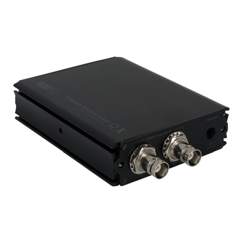
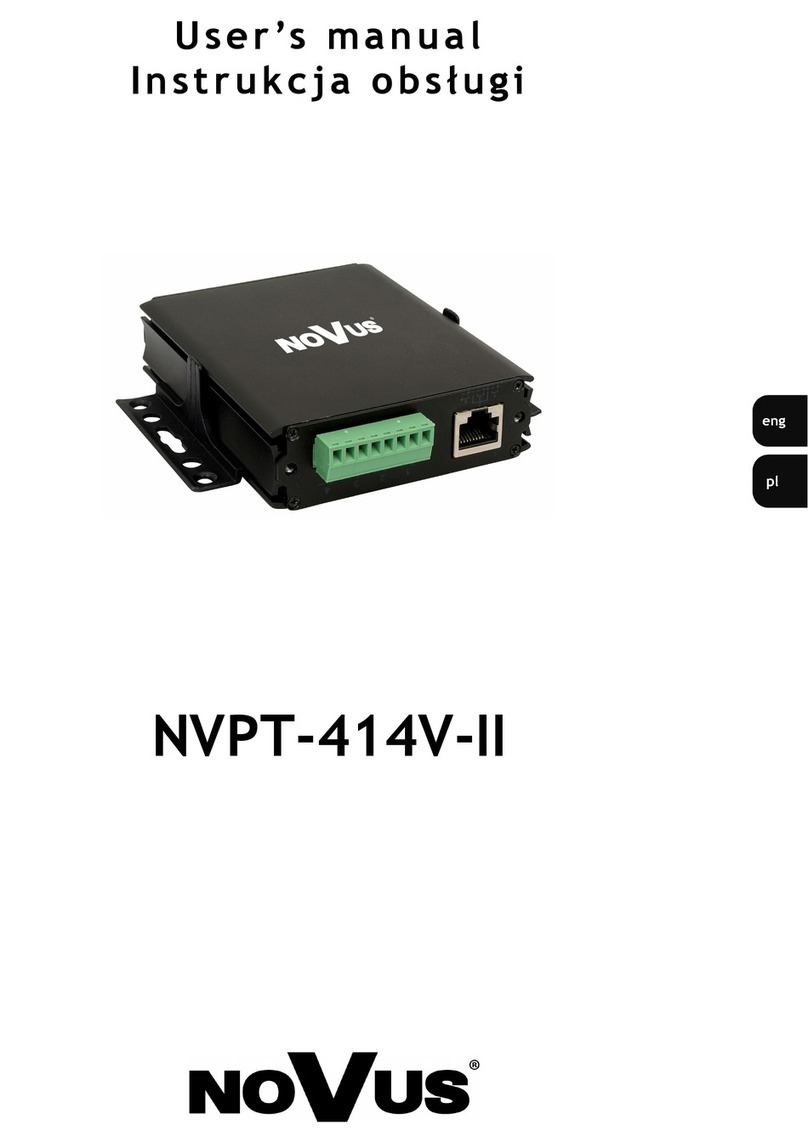
Novus NVPT-111VT User manual

NVPT-111VT
NVPT-111VTP
NVPT-414V
u s e r ’s m an u al
i n s t r u k c ja obsł u g i

NVPT-111VT, NVPT-111VTP, NVPT-414V - user's manual, ver. 2.1
All rights reserved © NOVUS Security Sp. z o.o.
2
INFORMATION
EMC (89/336/EEC) and LVD (73/23/EEC) Directives
CE Marking
Our products are manufactured to comply with requirements of the following directives
and national regulations implementing the directives:
• Electromagnetic compatibility EMC 89/336/EEC with further amendments
• Low-voltage LVD 73/23/EEC with further amendments. This directive applies to electrical
equipment designed for use with a voltage rating of between 50VAC and 1000VAC as well as 75VDC
and 1500VDC.
WEEE 2002/96/EC Directive
Information for users who want to get rid of electrical and electronic appliances
This product is marked according to the European Directive on Waste Electrical and
Electronic Equipment (2002/96/EC) and further amendments. By ensuring this product
is disposed of correctly, you will help to prevent potential negative consequences for
the environment and human health, which could otherwise be caused by inappropriate waste
handling of this product.
The symbol on the product, or the documents accompanying the product, indicates that this appliance
may not be treated as household waste. It shall be handed over to the applicable collection point for the
waste electrical and electronic equipment for recycling purpose. For more information about recycling
of this product, please contact your local authorities, your household waste disposal service or the shop
where you purchased the product.
2002/95/EC RoHS Directive
Out of concern for human health protection and friendly environment, we assure that our
products falling under RoHS Directive regulations, regarding the restriction of the use of
hazardous substances in electrical and electronic equipment, have been designed
and manufactured in compliance with the above mentioned regulation. Simultaneously,
we claim that our products have been tested and do not contain hazardous substances
whose exceeding limits could have negative impact on human health or natural environment.
Information
The device, as a part of professional CCTV system used for surveillance and control, is not designed
for self installation in households by individuals without technical knowledge.
The manufacturer is not responsible for any defects or damages resulting from improper,
or inconsistent with user’s manual, installation of the device in the system.

NVPT-111VT, NVPT-111VTP, NVPT-414V - user's manual, ver. 2.1
All rights reserved © NOVUS Security Sp. z o.o.
3
WARNINGS AND PRECAUTIONS
ATTENTION!
THE KNOWLEDGE OF THIS USER’S MANUAL IS AN INDESPENSIBLE
CONDITION OF A PROPER TRANSCEIVER OPERATING. YOU ARE KINDLY
REQUESTED TO FAMILIARIZE YOURSELF WITH THIS MANUAL BEFORE
STARTING THE DEVICE.
THE MANUAL SHOULD BE KEPT FOR FUTURE USE.
CAUTION!
THE COVER MUSTN’T BE TAKEN OFF.
ANY SELF-REPAIRS MUSTN’T BE EXECUTED.
ALL REPAIRS CAN BE EXECUTED ONLY BY QUALIFIED STAFF
OF THE AUTHORISED NOVUS SERVICE.
INFORMATION
All the data included in this manual are up to date at the moment of printing this manual. Novus
Security Sp. z o.o. reserves the right to amend this manual. The producer reserves the right to modify
parameters of the device and change its design without notice.

NVPT-111VT, NVPT-111VTP, NVPT-414V - user's manual, ver. 2.1
All rights reserved © NOVUS Security Sp. z o.o.
4
SPECIFICATION
1. SPECIFICATION
Notice: Maximum transmission distances are valid when only one pair is used. When more than one pair
in the cable is used maximum distances might be slightly shorter.
Notice: Maximum transmission distances are given for total cable length, twisted-pair plus possible
coaxial cable used e.g. as a patch-cords. The above distances, are given for camera monitor
connection. When DVR, multiplexer or quad is also used distance might be slightly shorter.
Notice: It is impossible to extend the above transmission distances by cascade connection of those passive
devices. In order to achieve longer distances active devices must be used.
Notice: With transmission over long distances slight image brightness and sharpness loss might be
noticeable. It's a normal phenomenon and it can't be considered as a device malfunction.
Model NVPT-111VT NVPT-111VTP NVPT-414V
Type Passive transmitter / receiver
Video Input / Output 1 x BNC, V
p-p
, 75Ω1 x BNC, V
p-p
, 75Ω4 x BNC, V
p-p
, 75Ω
Bandwidth
12 MHz
Transmission distance
color signal
Up to 400 m (only passive devices),
Up to 1200 m (with passive transmitter and active receiver
NVPT-A111VRH)
Transmission distance b/
w signal
Up to 600 m (only passive devices),
Up to 2000 m (with passive transmitter and active receiver
NVPT-A111VRH)
Dimensions
(mm) 60 (L) x 20 (W)
x 21(H)
20(L) x 21(W)
x 280(H)
(with 230mm coaxial
cable)
110(L) x 25(W)
x 78(H)
Weight
60 g 100 g 200 g
Case
ABS, black
Cable recommended
CAT 5 UTP, 0.5 mm
2

NVPT-111VT, NVPT-111VTP, NVPT-414V - user's manual, ver. 2.1
All rights reserved © NOVUS Security Sp. z o.o.
5
FEATURES
2. FEATURES
NVPT-111VT
Single-channel video transceiver for twisted-pair;
The passive device – no power supply required;
Connectors: 1 x BNC male, 2-pin screw terminal, RJ45;
Video transmission distances: b/w signal up to 600m and color signal up to 400m using only
passive devices or 1200m and 2000 using passive transmitter and active receiver
NVPT-A111VRH;
Built-in impedance coupler and noise filter serve as the additional protection against interference.
NVPT-111VTP
Single-channel video transceiver for twisted-pair;
The passive device – no power supply required;
Connectors: 1 x BNC male, 2-pin screw terminal, RJ45;
Video transmission distances: b/w signal up to 600m and color signal up to 400m using only
passive devices or 1200m and 2000 using passive transmitter and active receiver
NVPT-A111VRH;
Built-in impedance coupler and noise filter serve as the additional protection against interference;
230mm coaxial cable, ideal to connect with the image processors which have multi-BNC connectors
(multiplexer, DVR, matrix switcher)
NVPT-414V
Four-channel video transceiver for twisted-pair;
The passive device – no power supply required;
Connectors: 4 x BNC male, 8-pin screw terminal, RJ45; ;
Video transmission distances: b/w signal up to 600m and color signal
up to 400m using only passive devices or 1200m and 2000 using passive transmitter and active
receiver NVPT-A111VRH;
Built-in impedance coupler and noise filter serve as the additional protection against interference;

NVPT-111VT, NVPT-111VTP, NVPT-414V - user's manual, ver. 2.1
All rights reserved © NOVUS Security Sp. z o.o.
6
INSTALLATION
3. INSTALLATION
NVPT-111VT / NVPT-111VTP
NVPT-111VT / NVPT-111VTP transceivers utilize only one pair of wires for video transmission.
Please pay attention to proper polarization while making connections. Pins described as "+" from
a transmitter should be connected to pins described as a "+" on a receiver.
Devices are equipped with screw terminal and RJ-45 connector as well.
While making connection user can choose convenient connector type. It is possible to "mix" connector
types while making connection as long the proper polarization is kept.
8 1
RJ-45 connector view with a pin description Screw terminal view with pin description
Pin 7 <----> "+"
Pin 8 <----> "-"
+
++
+
-
--
-

NVPT-111VT, NVPT-111VTP, NVPT-414V - user's manual, ver. 2.1
All rights reserved © NOVUS Security Sp. z o.o.
7
INSTALLATION
NVPT-414V
NVPT-414V transceivers utilize one pair of wires for one video channel transmission. Please pay
attention to proper polarization while making connections. Pins described as "+" from a transmitter
should be connected to pins described as a "+" on a receiver.
Each channel in transmitter should be connected to corresponding channel in receiver (1st to 1st, 2nd to
2nd and so on).
Devices are equipped with screw terminal and RJ-45 connector as well.
While making connection user can choose convenient connector type.
It is possible to "mix" connector types while making connection as long the proper polarization is kept.
It is also possible to "mix" devices types, 4 and 1 channel as long the proper polarization is kept.
Pin 1 <----> "+" channel 1
Pin 2 <----> "-" channel 1
Pin 3 <----> "+" channel 2
Pin 6 <----> "-" channel 2
Pin 4 <----> "+" channel 3
Pin 5 <----> "-" channel 3
Pin 7 <----> "+" channel 4
Pin 8 <----> "-" channel 4
RJ-45 and clamp connector view with
a pin description
1 8

NOVUS Security Sp. z o.o.
ul. Puławska 431, 02- 01 Warszawa
tel.: (22) 546 0 700, fax: (22) 546 0 719
www.novuscctv.com
2007-09-24
This manual suits for next models
2
Table of contents
Other Novus Receiver manuals

Novus
Novus NR3700-O/G User manual

Novus
Novus PICOPOD NR7000 User manual

Novus
Novus NVPT-A121VT User manual

Novus
Novus NR2110-OG User manual

Novus
Novus NVPT-414V-II User manual

Novus
Novus NVPT-A122VRH User manual

Novus
Novus NVPT-A151VR-HD User manual

Novus
Novus NR2310-O/G User manual

Novus
Novus N4430-O-G User manual

Novus
Novus NR2310D-O/G User manual
Popular Receiver manuals by other brands

DX Engineering
DX Engineering DXE-RFS-SYS-4P manual

Denon
Denon AVR-485S brochure

Pioneer
Pioneer MVH-390BT owner's manual

Multiplex
Multiplex Hitec Optima D instruction manual

JVC
JVC KD-AVX11 - EXAD - DVD Player Installation & connection manual

Kenwood
Kenwood VRS-N8100 - AV / Digital Multimedia Receiver instruction manual