Novus NR2310-O/G User manual

USERS MANUAL
NR2310-O/G
REVISION
H
DATE
7/17/20
Page #:
1 of 21
www.novuspower.com
NR2310-O/G
10MHz Frequency Reference, OCXO, GNSS-Locked, 10-Channel
All information provide herein is the property of Novus Power Products LLC. The
information included may be reproduced without the permission of Novus Power
Products LLC for the purpose of operating the equipment.

USERS MANUAL
NR2310-O/G
REVISION
H
DATE
7/17/20
Page #:
2 of 21
www.novuspower.com
Table of Contents
Overview............................................................................................................................. 3
Crystal - The Time Base..................................................................................................... 6
GNSS Receiver................................................................................................................. 10
Typical Acceptance Test Performance Data..................................................................... 11
Typical Phase Noise Performance.................................................................................... 12
Controls and Indicators..................................................................................................... 13
Channel Status - Front Panel LEDs.............................................................................. 13
Alert –Front Panel LED............................................................................................... 13
Oven –Front Panel LED............................................................................................... 13
Rear Panel......................................................................................................................... 14
Channel 1 through 10 –BNC........................................................................................ 14
Alert - BNC................................................................................................................... 14
Antenna - SMA............................................................................................................. 14
Built-in Test.................................................................................................................. 15
Power Supplies.............................................................................................................. 15
Technical Specifications................................................................................................... 17
Performance.................................................................................................................. 17
Environmental and Mechanical .................................................................................... 18
8.0 Appendix A –Receiver Communication Specification.............................................. 21

USERS MANUAL
NR2310-O/G
REVISION
H
DATE
7/17/20
Page #:
3 of 21
www.novuspower.com
Overview

USERS MANUAL
NR2310-O/G
REVISION
H
DATE
7/17/20
Page #:
4 of 21
www.novuspower.com
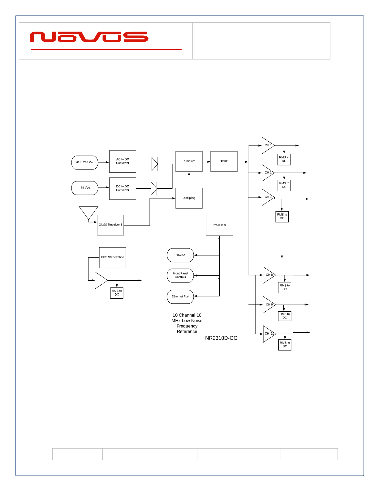
The NR2310-O/G is a GNSS-locked OCXO 10 MHz frequency reference with
PPS and RS232. The unit features auto-calibration so that the most recent
coefficients to compensate the OCXO for drift due to aging and/or temperature
are stored and applied to the OCXO during GPS loss-of-lock conditions. These
coefficients are updated after eight hours of continuous GPS locked state. This
effectively eliminates long-term OCXO changes.
The RS232 interface provides access to the NMEA-0183 data from the GPS at a
baud rate of 38.4K. The baud rate can be changed through the RS232 port using
commands described in Appendix A (Output Format Section).
The unit operates from AC power 90 to 240 VAC or optional DC source in the
range -60 to +60 VDC (in three ranges). The DC option can be primary or a
secondary source.
The outputs are 10 MHz sinewave at 13 dBm (1.0 Vrms). The outputs are short
circuit and transient protected.
PPS pulse is a LVCMOS signal and is also short and transient protected. The
PPS has an accuracy of 30 ns rms. The unit may be ordered with the PPS level
at 3.3 or 5 VDC CMOS levels and are capable of driving a 50 Ohm load (units
manufactured. after March 2020).
The GNSS transmits a wealth of data. The information is routinely used for
position and timing. This signal is what is used by all GNSS disciplined oscillators
for master timing.
The first part of the process is acquiring the GNSS satellites and deriving what is
called the PPS signal. This is a pulse that occurs once per second. Most GNSS
receivers will specify an accuracy for the leading edge in the range of ~20 ns
rms. Due to atmospheric conditions, multi-path and other effects, there is
considerable jitter on the pulse. This pulse, with exceptional long-term accuracy
of ~E-12, is the starting point for the GPSDO.
The PPS is used to derive a 10MHz signal. As you can imagine, the algorithms
for the generation of the 10MHz are very sophisticated. You are, in effect,
creating a 10MHz waveform with frequency measured once per second by a
waveform which has considerable jitter.
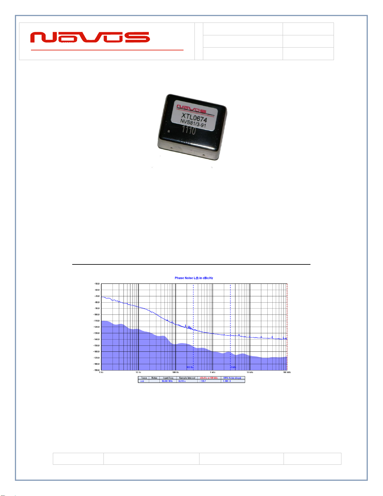
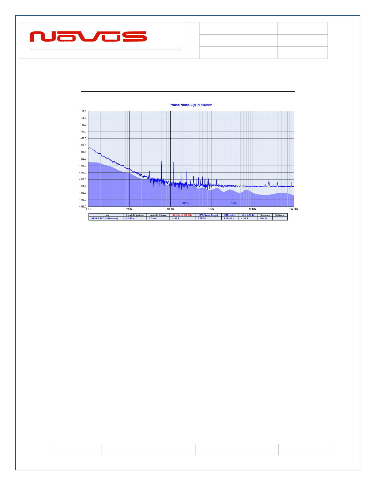
To get a useful frequency reference, the jitter (phase noise) of the frequency
reference must be improved. A very low bandwidth phase locked loop is used to
lock a high performance 10 MHz OCXO to the synthesized disciplined 10 MHz.

USERS MANUAL
NR2310-O/G
REVISION
H
DATE
7/17/20
Page #:
5 of 21
www.novuspower.com
By virtue of having a very low bandwidth, the high frequency jitter is dramatically
reduced. There are numerous tradeoffs - speed of acquisition, phase error,
stability, cost, etc. It is a complex feedback loop and as such, there are many
solutions. Noise on the final output is also affected by the noise in the system.
Noise from power supplies and other circuits can easily sum with the output
signal. Care has been taken throughout the design to achieve a high-quality
signal.
The phase noise of the output is now largely dominated by the voltage-controlled
oscillator. The oscillator is typically a crystal oscillator and the quality of that
device can vary significantly. The NR2310-O/G uses an oven-controlled oscillator
to provide an unlocked stability of under ±50 ppb/year.
The calibration feature continually monitors the correction coefficients developed
through GNSS timing information. These are sampled multiple times per day and
stored in non-volatile memory and in the event of a GPS loss, the saved
coefficients are applied to the OCXO. This effectively eliminates long-term
crystal drift.
The NR2310-O/G also incorporates built-in test to monitor critical parameters
such as the OCXO oven, power supplies and other functions. The built-in test
drives a front panel indicator and status is available via the RS232 port.
The GPS lock status is provided by a front panel indicator and via the RS232
port.
The NR2310-O/G draws less than 10 Watts of power.
The output of the OCXO is buffered and amplified. The buffering is completely
fault protected and is followed by ESD protection circuitry. The output is also
monitored for signal presence.
In addition to the signal presence built-in test, there is circuitry to determine if the
oven within the OCXO has failed. This is a very subtle failure as there would
appear to be a sine wave - but without a functional oven, the temperature stability
would be poor. If a failure is detected, the Alert LED will be activated and the
status relay will be opened. During the first fifteen minutes of operation, an alert
may occur as the oven brings the crystal up to temperature. This is normal and
will stop after approximately fifteen to thirty minutes of operation.

USERS MANUAL
NR2310-O/G
REVISION
H
DATE
7/17/20
Page #:
6 of 21
www.novuspower.com
Crystal - The Time Base
Novus crystal-based frequency reference products are based upon either TCXO
or OCXO technology. Temperature compensated crystal oscillators will normally
use an AT cut crystal and electronically compensate the device with temperature.
An OCXO device uses a SC (stress compensated) crystal and the part is held at
a fixed temperature to minimize temperature drift.
The TCXO implementation results in a temperature stable reference in the single
digit parts per million. An OCXO device affords a reference that is almost two
orders of magnitude more stable than the TCXO.
COMPARISON OF AN AT VERSUS A SC CUT CRYSTAL

USERS MANUAL
NR2310-O/G
REVISION
H
DATE
7/17/20
Page #:
7 of 21
www.novuspower.com
Over a broad temperature range, an AT performs very well and much easier to
compensate electronically. It is also a simpler crystal to manufacture than a SC
cut device. For applications where a stability of a few ppm is acceptable, a TCXO
can be a cost-effective alternative.
The SC cut results in a much higher Q device and achieves much lower phase
noise than the AT cut. The device is also more sensitive to pressure and
temperature variation and is mounted in temperature controlled hermetic
chamber.
OCXO oven temperature is in the range of 90°C. The devices heat-up and
become stable within ~ 5 minutes.
OCXO FREQUENCY ERROR FROM COLD START

USERS MANUAL
NR2310-O/G
REVISION
H
DATE
7/17/20
Page #:
8 of 21
www.novuspower.com
Typical OCXO
Another alternative for a frequency reference is an atomic reference. These
devices use a change in atomic state of an isotope of Cesium or Rubidium for
stability. Instead of a stability of ±50 ppb/year for a typical OCXO- stability of ±1
ppb/year is very common.
Atomic sources are very complex and while a very stable source, phase noise
performance may not be acceptable for many applications.
TYPICAL PHASE NOISE PERFORMANCE FOR A RUBIDIUM REFERENCE
For applications requiring the stability of an atomic source but also requiring low
phase noise a low phase noise OCXO is disciplined to an atomic source. The
phase noise for the NR2310-R/O has phase noise improved by well over 20 dB
by this technique.

USERS MANUAL
NR2310-O/G
REVISION
H
DATE
7/17/20
Page #:
9 of 21
www.novuspower.com
TYPICAL PHASE NOISE PERFORMANCE –RUBIDIUM WITH OCXO
When the stability of an atomic or crystal source is not sufficient, a GNSS
disciplined reference is an option. A GNSS receiver is installed and timing
information from the GNSS is used to discipline the timing device. Timing
accuracy to a few ppb is readily achievable.

USERS MANUAL
NR2310-O/G
REVISION
H
DATE
7/17/20
Page #:
10 of 21
www.novuspower.com
GNSS Receiver
The receiver and companion elements generate the GNSS sine wave, PPS and
NMEA serial link. The serial link conforms to NMEA 0183 protocol. The 26
channel, high-sensitivity, high-accuracy multi-GNSS receiver supports TRAIM,
GPS, GLONASS, QZSS, SBAS, Active Anti-Jamming and Advanced Multipath
Mitigation Functions.
Typical Antenna Specs:
Frequency Band 1574 –1607 MHz
Antenna Gain 2 dBic @ 90°
Amplifier Gain @ 3.0Vdc: 26dB (typ)
Polarization RHCP
Out-of-band Rejection >60dBc @ f0 ± 50MHz
Impedance 50Ω
VSWR 2.0 Max
DC Input 2.8V - 6V
Noise Figure <2.0dB
Power Consumption 25mA (typ)

USERS MANUAL
NR2310-O/G
REVISION
H
DATE
7/17/20
Page #:
11 of 21
www.novuspower.com
Typical Acceptance Test Performance Data
Date 6/7/2019 Model NR2310-OG
Tech MM Serial 23191284 Actual
Count
(sec)
Frequency
Deviation
ppb
Frequency
Deviation
ppb
110000000.000 0.043 10000000.000 0.011
CH1 Ch2 CH3 CH4 CH5 210000000.000 0.048 10000000.000 0.012
0.962 0.958 0.958 0.955 0.958 3 10000000.000 0.047 10000000.000 0.023
CH6 CH7 CH8 CH9 CH10 410000000.000 0.042 10000000.000 0.018
0.955 0.944 0.940 0.933 0.940 5 10000000.000 0.043 10000000.000 0.020
610000000.000 0.042 10000000.000 0.017
±15ppb 7 10000000.000 0.048 10000000.000 0.018
810000000.001 0.052 10000000.000 0.015
2.52 V PW 100 ms 9 10000000.000 0.045 10000000.000 0.007
10 10000000.000 0.042 10000000.000 0.018
Cal Exp Date 11 10000000.000 0.047 10000000.000 0.018
9/19/2019 12 10000000.000 0.043 10000000.000 0.016
9/18/2019 13 10000000.000 0.048 10000000.000 0.018
14 10000000.000 0.049 10000000.000 0.019
15 10000000.001 0.051 10000000.000 0.021
16 10000000.000 0.046 10000000.000 0.021
17 10000000.000 0.045 10000000.000 0.028
18 10000000.000 0.036 10000000.000 0.016
19 10000000.000 0.038 10000000.000 0.014
20 10000000.000 0.036 10000000.000 0.013
21 10000000.000 0.036 10000000.000 0.009
22 10000000.000 0.033 10000000.000 0.007
23 10000000.000 0.030 10000000.000 0.017
24 10000000.000 0.025 10000000.000 0.026
25 10000000.000 0.025 10000000.000 0.020
26 10000000.000 0.035 10000000.000 0.016
27 10000000.000 0.028 10000000.000 0.010
28 10000000.000 0.026 10000000.000 0.021
29 10000000.000 0.023 10000000.000 0.020
30 10000000.000 0.024 10000000.000 0.020
Frequency Specification Limit
Equipment
Frequency Counter
Tektronics 2024B
Model
Agilent 53230a
PPS @ 200Ω
Oscilloscope
Frequency (unlocked)
Amplitude
Novus- Reference Group
201 N Forest Ave Suite 225
Independence, MO 64050
866 984 6887
Frequency (locked)
-4.000
-3.000
-2.000
-1.000
0.000
1.000
2.000
3.000
4.000
135791113 15 171921 23 25 2729
Deviation ppb
count (seconds)
Frequency Locked
-15
-10
-5
0
5
10
15
1357911 13 15 17 19 21 23 25 27 29
Deviation ppb
count (seconds)
Frequency Unlocked

USERS MANUAL
NR2310-O/G
REVISION
H
DATE
7/17/20
Page #:
12 of 21
www.novuspower.com
Typical Phase Noise Performance
The NR2310-O/G delivers a low phase noise, which can be seen in the sample
production test below.
NR2310-O/G Phase Noise Measurement

USERS MANUAL
NR2310-O/G
REVISION
H
DATE
7/17/20
Page #:
13 of 21
www.novuspower.com
Controls and Indicators
Channel Status - Front Panel LEDs
A local fault will cause the indicator to go from green to red. A channel fault will
not cause a general alert but will illuminate red on the channel indicator.
Alert –Front Panel LED
There are numerous critical circuits in the unit. These are monitored and a failure
of any of these will initiate an alert condition. The ALERT LED on the front panel
will go from green to flashing red and the alert relay will open. The alert relay is
accessed by a BNC connector on the rear panel. The normal operating state is
the relay will be closed.
Oven –Front Panel LED
The GPSDO incorporated into NR2310-O/G monitors the oven in two different
ways. For units shipped before February 2016, the front panel OVEN LED was
used to indicate oven and GPS lock status:
Oven LED GREEN, Constant Oven Good, GNSS lock
GREEN, Flashing Oven Good,GNSS unlock
RED Oven Fail
After February 2016 (serial number 15160751 or greater)
Oven LED GREEN Constant Oven Good,GNSS Lock
RED Flashing Oven Fail, Lock Status Fail
Basically, the method of monitoring the lock status was changed to monitor the
NMEA data string and the control loop voltage. If the NMEA string indicated lock
and the control loop voltage was within the bounds for normal values, the loop
was locked. The control loop voltage will track a range of failures that keep the
PLL from locking.
Since the NR2310-O/G is a GNSS locked reference, during power-on, the OVEN
LED will flash during tracking, and until a GNSS lock status is achieved. This can
take up to thirty minutes –typically < 10 minutes.

USERS MANUAL
NR2310-O/G
REVISION
H
DATE
7/17/20
Page #:
14 of 21
www.novuspower.com
Rear Panel
STATUS
CH1 CH2 CH 3 CH4 CH5 CH6 CH7 CH8 CH9 CH10
Channel 1 through 10 –BNC
Output from each of the ten channels: 10Mhz, 1 Vrms, 50Ω BNC connectors.
Each output is fault and electrostatic discharge protected. Each output is
independent and any output can be faulted for an indefinite period of time with no
permanent damage.
Each output is connected to a monitor circuit that detects a local fault on the
output. The fault status is indicated on the front panel and on the LCD when in
the channel status mode. The fault status and the protection on each output
facilitates installation and helps prevent damage during installation. A channel
fault will not activate an ALERT state and the status relay will not be opened.
Alert - BNC
Connects to the status relay. Contacts rated at 20 VDC/VAC, 0.5 Amps. Contacts
are closed during normal operation. Open relay indicates failure.
Antenna - SMA
SMA female antenna connection. Provides internal 3.3VDC power at 25mA max.
The Novus NA103A pole mount antenna or the Novus NA106 magnetic mount
antenna are recommended for optimal performance.

USERS MANUAL
NR2310-O/G
REVISION
H
DATE
7/17/20
Page #:
15 of 21
www.novuspower.com
Novus NA103A Novus NA106
Built-in Test
The built-in test monitors the following:
Power Supplies: All power supplies are monitored. If a supply fails to
meet test limits, an alert is generated.
Channel Faults: If a channel fault is detected, an indication is given for the
individual channel, but an alert is not generated.
Power Supplies
The unit is designed to accept power in the range 90 to 264VAC, 50 to 60 Hz.
This allows global application. The design is such that no action need be taken to
operate from global power types. This feature alleviates installation damage that
occurs in designs that require an input power switch mode be used.
There is an EMI filter between the internal power supply and the available power
being used. This filter minimizes the electrical noise from entering the circuitry
and negatively impacting noise performance. Also, in most applications, the
equipment that surrounds this unit is sensitive and the filter also reduces noise
that could impact the performance of other equipment.

USERS MANUAL
NR2310-O/G
REVISION
H
DATE
7/17/20
Page #:
16 of 21
www.novuspower.com
The demands on the power supplies are two-fold - maximum efficiency and
minimum noise. Maximum efficiency reduces power dissipation in the unit.
Temperature impacts reliability and stability. To achieve maximum efficiency, the
primary converter is a switching converter with an efficiency of approximately
90%.
High efficiency of switching converters is well known and holds a major position
in the power supply industry. But one of the problems with a switching converter
is noise. By its nature, a switching power supply must use fast rise and fall times
of the switching elements. These fast edges generate high frequency noise. The
power supply chosen has a noise level that is more than 50dB below primary. To
further reduce noise, the power supply is in its own enclosure and is followed by
a noise filter. The filtered power is then used by width bandwidth linear regulators
to further reduce noise.

USERS MANUAL
NR2310-O/G
REVISION
H
DATE
7/17/20
Page #:
17 of 21
www.novuspower.com
Technical Specifications
Performance
Output
10 MHz,1.0 Vrms ±0.2, into 50 Ohms, 10 channels, Sine, BNC
Harmonic Distortion
< -30 dBc
First Year Freq Stability
± 50 ppb (unlocked)
Temperature Stability
± 10ppb (unlocked)
Daily Aging OCXO
± 5 ppb/day (unlocked)
Yearly Aging
± 50 ppb (unlocked)
Allan Deviation
< 1E-11 @300 seconds
Phase noise
1 Hz
-95 dBc/Hz
10 Hz
-120 dBc/Hz
100 Hz
-145 dBc/Hz
1 kHz
-150 dBc Hz
PPS
Amplitude for 1PPS
3.3 VDC CMOS (5 VDC option)
Pulse width for 1PPS
Programmable 1 to 500ms in 1 ms steps
Rise time for 1PPS
<10 ns (faster edge available)
Jitter
GNSS-PPS < 10ns
Connector
SMA
Load Impedance
50 Ohm
Location
rear
Remote interface & control
Protocol
RS232 NMEA-0183
Connector
DB-9
Location
Rear panel
Protocol
Bit plus stop
Standard Baud Rates
Selectable 4800, 9600, 19200, 38400, 57600 or 115200 bps
GNSS receiver
GPS L1 C/A, GLONASS L1OF, QZSS L1 C/A, SBAS L1 C/A
(Ready): Galileo E1B/E1C, QZSS L1S
Channels
26 channels (GPS, GLONASS, QZSS, SBAS)
Sensitivity
GPS
Tracking: -161 dBm
Hot Start: -161 dBm
Warm Start: -147 dBm
Cold Start: -147 dBm
Reacquisition: -161 dBm
GLONASS

USERS MANUAL
NR2310-O/G
REVISION
H
DATE
7/17/20
Page #:
18 of 21
www.novuspower.com
Tracking: -157 dBm
Hot Start: -157 dBm
Warm Start: -143 dBm
Cold Start: -143 dBm
Reacquisition: -157 dBm
With Novus recommended antenna
Antenna with LNA
Antenna Power
3.5 VDC, < 35 mA (on center conductor) (factory configurable to 5
VDC)
Frequency
1574-1607 MHz
Nominal Gain
2 dBic
Amplifier Gain
26 dB
Noise Figure
< 2.0 dB
Out of Band Rejection
Fo±50MHz=60 dBc, Fo±60 MHz
DC Current
Environmental and Mechanical
Operating Temperature
0 to 50°C non-condensing
Storage Temperature
-40 to 70°C
Height
1RU (~1.73”)
Width
19.0 inches
Depth
12.0 inches
AC input
90 to 250 VAC, 50/60hz, less than 10 watts
This document is copyright © July 24, 2020 Novus Power Products LLC. All rights
reserved. This document is provided for information purposes only; contents are subject
to change without notice. It is not warranted to be error-free, nor subject to any other
warranties or conditions including implied warranties and conditions of merchantability or
fitness for a particular purpose.

USERS MANUAL
NR2310-O/G
REVISION
H
DATE
7/17/20
Page #:
19 of 21
www.novuspower.com
LIMITED HARDWARE WARRANTY
Novus Power Products (hereinafter Novus) warrants its products to the original end user (“original
purchaser”) and warranty is not transferrable. Novus guarantees that the NOVUS hardware products that
you have purchased from NOVUS are free from defects in materials or workmanship under normal use
during the LIMITED WARRANTY PERIOD. The LIMITED WARRANTY PERIOD starts on the date of
shipment and for the period of 1 (one) year to be free from defects caused by faulty materials or poor
workmanship, provided:
(a) NOVUS is notified in writing by Buyer of such defect prior to the expiration of the warranty period, and
(b) after receiving return authorization –RMA- from NOVUS, the defective item is returned with
transportation prepaid to NOVUS, Independence, Missouri, with transportation charges prepaid by Buyer
…see RMA policy in Terms and conditions, and
(c) NOVUSs’ examination of such unit shall disclose to its satisfaction that such defect(s) exist and have not
been caused by misuse, neglect, improper installation, improper storage, unauthorized modifications,
inadequate maintenance, operation outside the environmental specifications for the product, repair
alteration, or accident. NOVUS assumes no risk or liability for results of the use of products purchased from
it, including but without limiting the generality of the foregoing: (1) the use in combination with any electrical
or electronic components, circuits, systems, assemblies or any other materials or substances; (2)
unsuitability of any product for use in any circuit or assembly. Removal or tampering with tamper-proof label
on merchandise will void warranty coverage unless with the written authorization from NOVUS
(d) an evaluation fee will be charged to Buyer to cover inspection and testing costs for any item returned by
Buyer under this paragraph which is found to be within specifications and/or otherwise not the responsibility
of NOVUS under the terms and conditions of this paragraph or any other part of this Agreement..
Your dated sales or delivery receipt is your proof of the purchase date. You may be required to provide
proof of purchase as a condition of receiving warranty service. You are entitled to hardware warranty service
according to the terms and conditions of this document if a repair to your NOVUS product is required during
the limited warranty period. Our obligation at NOVUS is limited to repair or replace products which prove to
be defective.
Should Novus be unable to repair or replace the product within a reasonable amount of time, the customer’s
alternate remedy shall be a refund of the purchase price upon return of the product to Novus. The liability of
NOVUS under this warranty is limited to replacing, repairing or issuing a credit, at its option, for any such
item returned by Buyer under the terms of this warranty.
EXCLUSIONS: The above warranty shall not apply to defects resulting from improper or inadequate
maintenance by the customer, customer-supplied software or interfacing, unauthorized modification or
misuse, operation outside of the environmental specifications for the product or improper site preparation
and maintenance (if applicable). For probes, cables, antennas and accessories, the warranty period is 90
(ninety) days.
PRODUCT SPECIFICATIONS: Published specifications whether contained herein or in any other materials
or documents distributed to Buyer by Novus do not become final or binding on NOVUS until approved by
NOVUS. NOVUS expressly reserves the right to change or modify specifications at any time without prior
notice.
WARRANTY LIMITATIONS: NOVUS MAKES NO OTHER WARRANTY, EITHER EXPRESSED OR
IMPLIED, WITH RESPECT TO THIS PRODUCT. NOVUS SPECIFICALLY DISCLAIMS THE IMPLIED
WARRANTIES OF MERCHANTABILITY OR FITNESS FOR A PARTICULAR PURPOSE.
IN ALL CIRCUMSTANCES NOVUS’ MAXIMUM LIABILITY IS LIMITED TO THE PURCHASE PRICE OF
THE PRODUCTS SOLD. NOVUS SHALL NOT, UNDER ANY CIRCUMSTANCES BE LIABLE UPON A
CLAIM OR ACTION IN CONTRACT, TORT, INDEMNITY OR CONTRIBUTION OR OTHER CLAIMS
RELATING TO THE PRODUCTS IT SELLS WHICH EXCEEDS THIS LIABILITY LIMIT. NOVUS SHALL
NOT BE LIABLE FOR THIRD PARTY CLAIMS FOR DAMAGES AGAINST THE CUSTOMER, OR FOR
MALFUNCTION, DELAYS, INTERRUPTION OF SERVICE, LOSS OF BUSINESS, LOSS OR DAMAGE TO
EXEMPLARY DAMAGES, WHETHER OR NOT NOVUS HAS BEEN MADE AWARE OF THE POSSIBILITY
OF SUCH CLAIMS OR DAMAGES.

USERS MANUAL
NR2310-O/G
REVISION
H
DATE
7/17/20
Page #:
20 of 21
www.novuspower.com
.
LIMITATION OF REMEDIES: REGARDLESS OF WHETHER ANY REMEDY SET FORTH HEREIN FAILS
OF ITS ESSENTIAL PURPOSE, IN NO EVENT WILL NOVUS BE LIABLE TO YOU FOR ANY SPECIAL,
CONSEQUENTIAL, INDIRECT OR SIMILAR DAMAGES, INCLUDING, WITHOUT LIMITATION, DAMAGES
FOR LOSS OF BUSINESS PROFITS, BUSINESS INTERRUPTION, LOSS OF DATA OR BUSINESS
INFORMATION (OR OTHER PECUNIARY LOSS) ARISING OUT OF THE USE OF OR INABILITY TO USE
THE HARDWARE SUPPLIED THEREWITH EVEN IF NOVUS OR ANYONE ELSE HAS BEEN ADVISED
OF THE POSSIBILITY OF SUCH DAMAGES, OR FOR ANY CLAIM BY ANY OTHER PARTY. EXCLUDED
DAMAGES SHALL INCLUDE, BUT ARE NOT LIMITED TO: COSTS OF REMOVAL AND INSTALLATION,
LOSSES SUSTAINED AS THE RESULT OF INJURY TO ANY PERSON, OR DAMAGE TO PROPERTY.
EXCLUSIVE REMEDIES: THE REMEDIES PROVIDED HEREIN ARE THE CUSTOMERS’ SOLE AND
EXCLUSIVE REMEDIES. IN NO EVENT SHALL NOVUS BE LIABLE FOR ANY DIRECT, INDIRECT,
SPECIAL, INCIDENTAL, OR CONNSEQUENTIAL DAMAGES, WHETHER BASED ON CONTRACT,
TORT, OR ANY OTHER LEGAL THEORY.
Other Novus Receiver manuals

Novus
Novus NVPT-A122VRH User manual

Novus
Novus NVPT-414V-II User manual

Novus
Novus NVPT-A121VT User manual

Novus
Novus NR2110-OG User manual

Novus
Novus NVPT-A151VR-HD User manual

Novus
Novus NR2310D-O/G User manual

Novus
Novus NVPT-111VT User manual

Novus
Novus PICOPOD NR7000 User manual

Novus
Novus N4430-O-G User manual

Novus
Novus NR3700-O/G User manual