Dat a upload
Sta rt
Wire Mapp ing
RJ11 BNC
RJ4 5 CAT6
Testi ng...
Cab le ope n or too s hort !
12345678G
M:
R: 3 4 5 6 7 8 G
W i r e M a p :R e m o t e
12345678G
M:
R:
1 2 3 4 5 6 7 8 G
12X45678G
M:
S:
1 2 X 4 5 6 7 8 G
pin 3:broken
123XX678G
M:
R:
1 2 3 X X 6 7 8 G
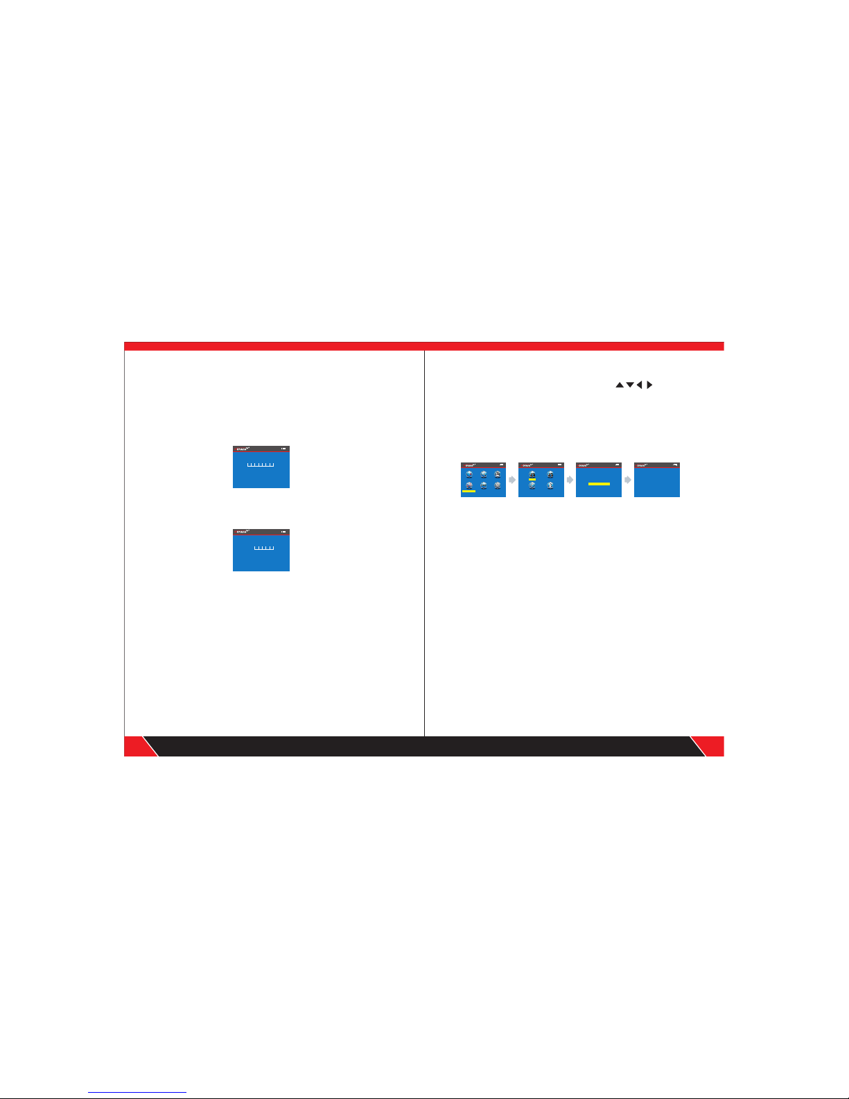
a.Cable line-to-line test ( eg: Network cable):
After entering main menu, move the cursor button to cable on-off test.
Then press OK; at this time, choose network cable, press OK, it
will enter into test the network cable menu. And after that, choose START
and connect the RJ45, the result will show you directly; but you also can
export the data and the tested result will into the TF card, the following
interface is shown indicating test is in process:
Test result 1: Unload or the cable not connected well
If the cable not inserts the main tester interface, it will show you this:
At this time, press to return to the main menu, and then press “ENTER”
key for re-test.
Test result 2: Short circuit
If there is short circuit with the cable and terminal, it will show as below:
(Short circuit with 3 and 6)
At this time, press to return to the main menu, and then press “ENTER”
key for re-test.
Test result 3: correct connection
If the device connects corrected, the tester can check remote identifier (R),
or local port (S) cables. If Verify the tested cable with remote ( R) or local
port (S), it can test STP network cable , and the picture will show you as
below :
R = Remote identifier's foot for RJ 45
S= Local foot of RJ45 port for scan
M= Local foot for RJ45 main interface
G = STP network cable
If you press it means back to the last menu and press OK means test
again or back to the main menu for re-test.
Test result 4: open circuit (Local test)
When local test and meet open circuit, it will show as below:
In the figure, “X” shown in “3” position, indicates there is open circuit.
Note: Because network cable is made of pair cores, if there is open circuit,
it will show faults in pairs, just as above "4" &" 5". it means either "4" pin or
"5" pin exists an open circuit, or both "4" and "5" exist an open circuit.
Test result 5: open circuit (Remote test)
In the figure, “X” shown in “4” and “5” pin position, indicates there is open
circuit in “4” and “5” pin of the remote pin.
09 10
Your excellent helper in cable test! Your excellent helper in cable test!
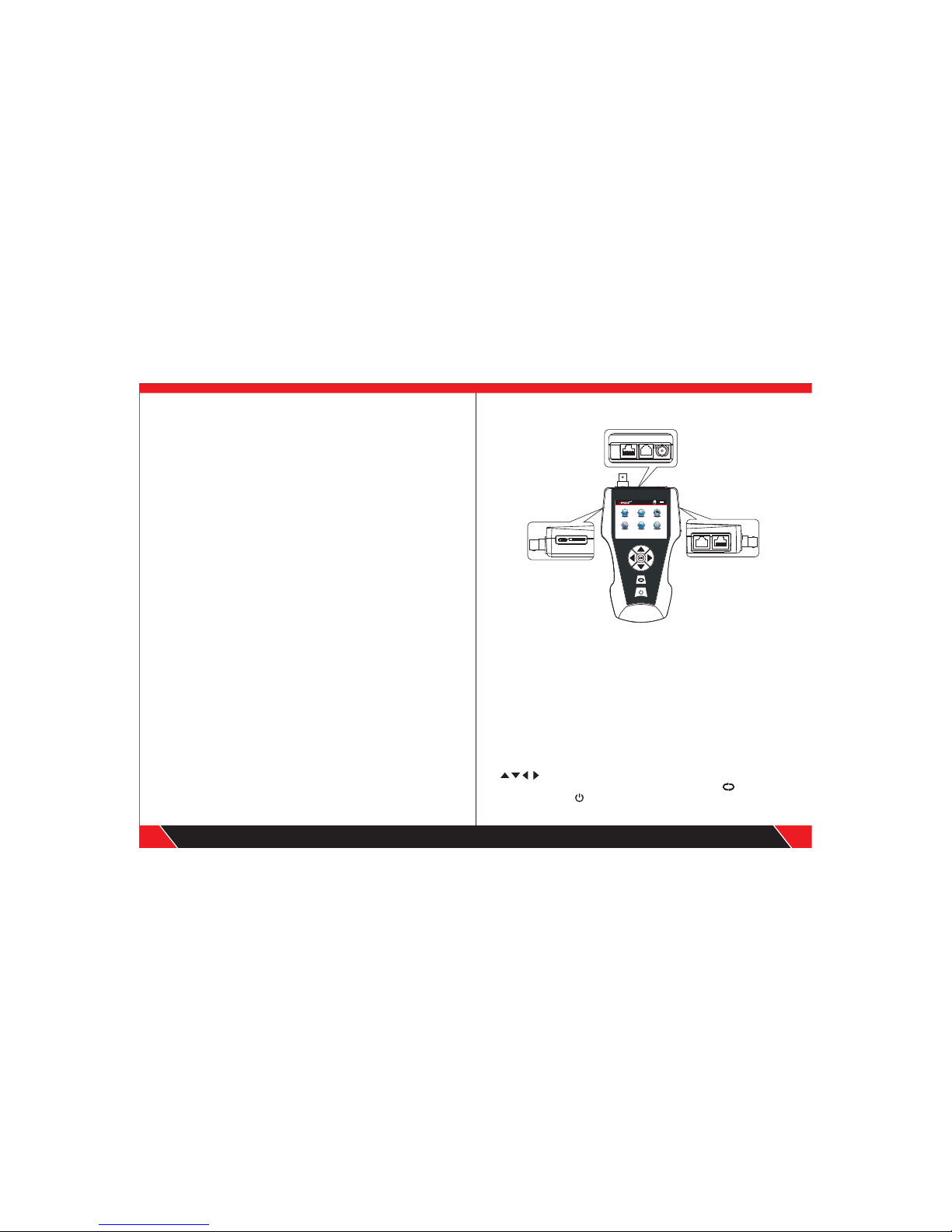
Wire Ma pping Sc an Cab le
Set
P i n g
Menue
POE Te st
Cabl e Leng th
RJ45 Wire M appin g R J45 Wi re Mappi ng
RJ4 5 Wir e Mapping
RJ4 5 Wir e Mapping
R J 4 5 Wi r e m a p p i n g
Tes t mode : Main +Remo te
Cab le cond itio n: go od
Tes t mod e:lo cal
R J 4 5 Wi r e m a p p i n g
R J 4 5 Wi r e m a p p i n g
pin 45:broken
Tes t mode :loca l