NRD Alphaboost AB-TC-1 Owner's manual

NRD USA / 2937 Alt Boulevard / PO Box 310 / Grand Island, NY 14072-0310
PHONE7167737634/FAX7167737744/EMAIL[email protected]/WEBwww.nrdllc.com
NRDAsiaPte.Ltd/114LavenderStreet#08‐90CTHub2Singapore338729
PHONE+6566791707/EMAIL[email protected]/WEBwww.nrdllc.com
- 1 -
Alphaboost_Manual-1/19
Installation / Operation / Maintenance
Staticmaster Alphaboost
Model AB-TC-1 & AB-TC-1B
Contents
Alphaboost™ System - General Description Page 2
Model: AB-TC - Control System Page 2
Model: AB-ABH - Ionizing Head Page 3
Model: 2U500 – Staticmaster® Ionizer Page 3
Model: AB-TC-1B – Alphie Page 3
Installation Page 4
AB-ABH Ionizing Head Installation Page 3
2U500 Staticmaster® Installation Page 4
AB-TC Controller Installation Page 4
Operation Page 4
2U500 Staticmaster® Ion Source Page 5
Cleaning Page 5
IEC Indications Page 5
Specifications Page 5
Warranty Page 6

NRD USA / 2937 Alt Boulevard / PO Box 310 / Grand Island, NY 14072-0310
PHONE7167737634/FAX7167737744/EMAIL[email protected]/WEBwww.nrdllc.com
NRDAsiaPte.Ltd/114LavenderStreet#08‐90CTHub2Singapore338729
PHONE+6566791707/EMAIL[email protected]/WEBwww.nrdllc.com
- 2 -
Alphaboost_Manual-1/19
Please Observe The Following
NOTICE
Please review the information in this manual prior to operating the Alphaboost™ in a work environment.
NOTICE
Please keep this document in a convenient place to refer to as a guide.
Alphaboost™ System - General Description
The Alphaboost™ in-tool ionizer is designed for control of static electricity in precision weighing balances and
scales. It utilizes a Staticmaster® Model 2U500 Alpha source to generate air ions and the ambient air flow along
with a modest acceleration voltage (called the Boost Voltage) in order to deliver the ions to the object(s) to be
neutralized. The system Model AB-TC includes; (1) controller, (1) head, (1) 2U500, (1) BF3 EZ Mount.
Connections are done by coaxial cable with high reliability MHV coaxial connectors.
Model: AB-TC - Controller
The AB-TC controller (see figure below) is used to create the waveform to drive the ions away from the ionizing
head. It is factory preset for
ON time for each polarity of the Boost Voltage
The amplitude of the ionizer Boost Voltage
The Duty Cycle of the Boost Waveform
The controller includes a readout of the duty cycle (Balance) setting of the controller with a resolution of 1%. While
the setting of the timing is preset at the factory, it can be observed as the green LED flashes. The red LED indicates
a failure of the controller, either by high voltage going out of regulation or polarity switching of the source stopping.
The most likely cause of this alarm is a short circuit at the ionizing head caused by an external object. Such a short
is not damaging to the controller.
Auxiliary Connector
The rear connector provides optional control and monitoring signals which can be used for a variety of purposes.
The Pin-outs of the connector are as follows:
G1: Ground
G2: Ground
NC: No function, spare
A: Alarm Output
R: Remote shutdown
O: HV Monitor Output. Source impedance 1 GW so monitor with a 1 MW probe results in 1000:1 attenuation of
signal. (±2.4 V max)
Boost Output
Balance
Read Out
Powe
r
Switch
DC Powe
r
Input
–
24 VDC
Red LED
Ground Connecto
r
Green LED
A
uxiliary Connector

NRD USA / 2937 Alt Boulevard / PO Box 310 / Grand Island, NY 14072-0310
PHONE7167737634/FAX7167737744/EMAIL[email protected]/WEBwww.nrdllc.com
NRDAsiaPte.Ltd/114LavenderStreet#08‐90CTHub2Singapore338729
PHONE+6566791707/EMAIL[email protected]/WEBwww.nrdllc.com
- 3 -
Alphaboost_Manual-1/19
Model: AB-ABH - Ionizing Head
The Ionizer head works with the Staticmaster® model 2U500 Alpha source (sold separately). The Boost Output of
the AB-TC Controller connects up to 4 ionizing heads when using the Splitter model AB-SPL (sold separately).
AB-ABH Ionizing Head AB-SPL 1 to 4 Splitter
Model: 2U500 – Staticmaster® Ionizer
The model 2U500 Staticmaster® is a small, self-powered ion producing device which contains 500 µCi of 210Po.
All NRD ion sources are encapsulated in precious metals by means of a special patented process. This results in a
static eliminator which resists oxidation, solvents, heat, cold and vibration.
Dimensions:
AB-TC-1B Alphie Assembly
The Alphie assembly includes:
AB-TC Controller
2U500 Staticmaster®
AB-ABH - Ionizing Head
AB-TC – Controller
Base

NRD USA / 2937 Alt Boulevard / PO Box 310 / Grand Island, NY 14072-0310
PHONE7167737634/FAX7167737744/EMAIL[email protected]/WEBwww.nrdllc.com
NRDAsiaPte.Ltd/114LavenderStreet#08‐90CTHub2Singapore338729
PHONE+6566791707/EMAIL[email protected]/WEBwww.nrdllc.com
- 4 -
Alphaboost_Manual-1/19
Installation
Installation of the Alphaboost™ Ionization System involves mounting and wiring the components in an arrangement
that satisfies the environment and power requirements of your application. Procedures may vary according to your
applications need. The Alphaboost™ Ionization System is intended to be used in an Analytical Balance application.
In such an application, the ionizer can easily provide enough output to discharge samples placed on the analytical
balance weighing pan. The Alphaboost™ controller is to be placed near the Analytical Balance(s) in a convenient
and visible position.
Note: the Alphaboost™ Ionization System is not to be connected to a power source while being installed or
serviced.
AB-ABH Ionizing Head Installation
1. Apply double sided tape to metal electrode on the AB-ABH ionizing head.
2. Attach the AB-ABH ionizing head to the outside of top panel of the Analytical Balance Draft Chamber.
Center metal electrode, as close as possible, over the weighing pan.
3. Attach BF3 EZ Mount to inside of top panel of the Analytical Balance. Center under metal electrode on
AB-ABH ionizing head.
2U500 Staticmaster® Installation
The 2U500 Staticmaster slides into the BF3 EZ Mount that is attached inside the Analytical Balance.
AB-TC Controller Installation
1. Locate the AB-TC Controller in a accessible and visible position that is within reach of the two (2) meter
cable of the AB-ABH Ionizing Head.
2. Connect the AB-ABH Ionizing Head cable to the Boost Output connection on back of the AB-TC
Controller. If connecting multiple AB-ABH Ionizing Heads, use AB-SPL Splitter. A maximum of four (4)
AB-ABH Ionizing Heads can be connected to one (1) AB-TC Controller.
3. Connect the AB-TC Controller to a proper ground using ground connector on back of the controller.
Without being connected to a proper ground, the AlphaBoost will exhibit an uncontrolled offset.
4. Connect the supplied 24V power supply to the power input on back of the AB-TC Controller. The AB-TC
Controller requires 24V @ <200mA to operate.
Operation
Follow the steps below to correctly power the Alphaboost™ System.
Analytical Balance
top panel
Metal
Electrode
BF3 EZ Moun
t
(included)
2U500
Staticmaster
(sold separately)
Double sided
tape
AB-ABH
Ionizing Head
A
B-ABH
Ionizing Head

NRD USA / 2937 Alt Boulevard / PO Box 310 / Grand Island, NY 14072-0310
PHONE7167737634/FAX7167737744/EMAIL[email protected]/WEBwww.nrdllc.com
NRDAsiaPte.Ltd/114LavenderStreet#08‐90CTHub2Singapore338729
PHONE+6566791707/EMAIL[email protected]/WEBwww.nrdllc.com
- 5 -
Alphaboost_Manual-1/19
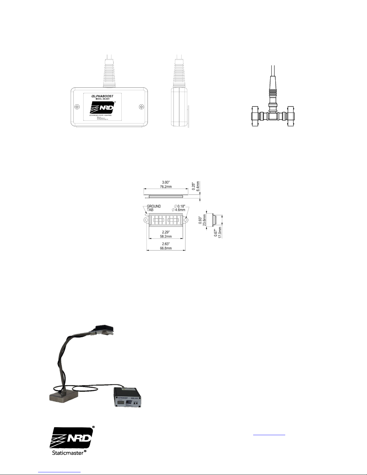
1. Ensure the AB-ABH Ionizing Head(s) are connected to the AB-TC Controller according to guidelines in
the installation section.
2. Plug the controller into a properly grounded outlet and turn power switch, located on the back of the unit, to
“ON”.
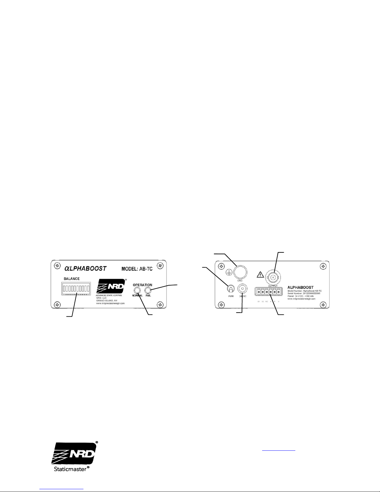
3. The green LED on the front of the AB-TC Controller should be on. If the red LED is on, or no LEDs are
on, this indicates a problem. Check for loose connections and if problem continues contact NRD, LLC for
assistance.
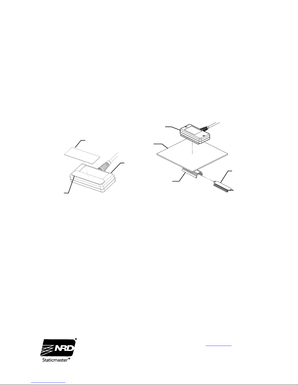
2U500 Staticmaster Ion Source
To maintain peak performance it is recommended to replace the 2U500 Staticmaster annually. Notification will be
given prior to the end of each year. Upon arrival of a replacement, change out the 2U500 Staticmaster and send the
old 2U500 to NRD LLC.
Cleaning
Use only a diluted IPA solution and a cleanroom-compatible cloth to clean any accumulated dirt on the controller or
ionizing head(s). Change cloth frequently to ensure that the dirt is completely removed. Do not use any solvents
that may damage the powder coat finish of the controller.
IEC Indications
High Voltage – the rear panel output of the AB-TC Controller is via an MHV connector. The voltage on this
connector can be as high as ±2400V. Note that the source impedance is in excess of 1MW so no harm or discomfort
will come to the operator by touching the contact.
The voltage source on the board is much lower impedance and, as such, contact with high voltage section of the
circuit board would be painful. This instrument uses high voltages that can cause personal injury. Before servicing,
shut down the instrument and disconnect the instrument from line power. It is recommended that the AB-TC
Controller not be opened.
The MHV connector on the chasis and the mating cable connector are both rated at 5000V. The RG 59 cable used
to connect the AB-TC Controller to the AB-ABH Ionizing Head is rated at a working voltage of 2400V.
Rear Panel Auxiliary Connector signals do not exceed 10V and require only insulation of connections to protect
against 10V.
Note: if the equipment is used in a manner not specified by the manufacturer, the protection provided by the
equipment may be impaired.
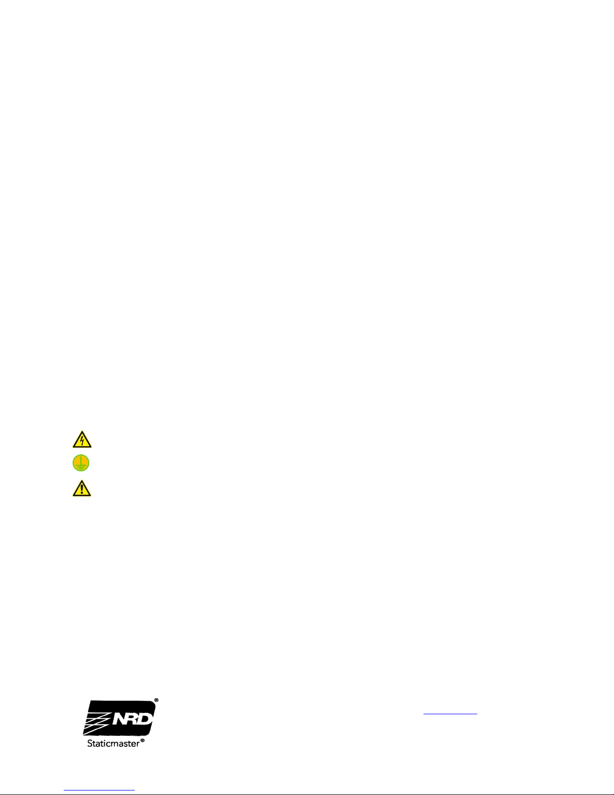
- This symbol means that there is high voltage present at this connector.
- This symbol means that it is necessary to connect this binding post to ground for proper operation of this
instrument.
- This symbol means that in order to have safe and proper operation of the device, the user should read the
manual.
Specifications:
Ionization Source: 500 µCi of 210Po. (provides full ionization performance for 12 months)
Boost: ±2400 V, Output from Model AB-TC via MHV connector.
Operating Period: 500 ms
Balance Voltage: Factory preset
Operating Range: AB-ABH Ionizing Head, 0° C to 80° C
AB-TC Controller, 5° C to 50° C
Power Requirement: 24 V DC, <200 mA (provided by 100 - 240 V inline power supply)
Offset Voltage: Factory preset
Alarm Condition: Positive or Negative Boost out of regulation by 5% or actual output ceases to
cycle.
Alarm Output: User Selectable either contact closure or pull up voltage to +5 V (user option).

NRD USA / 2937 Alt Boulevard / PO Box 310 / Grand Island, NY 14072-0310
PHONE7167737634/FAX7167737744/EMAIL[email protected]/WEBwww.nrdllc.com
NRDAsiaPte.Ltd/114LavenderStreet#08‐90CTHub2Singapore338729
PHONE+6566791707/EMAIL[email protected]/WEBwww.nrdllc.com
- 6 -
Alphaboost_Manual-1/19
Either positive or negative logic (user option). Output on rear panel terminal
strip connector.
Dimensions: AB-ABH Ionizing Head 3.5” x 1.8” x 0.8”
BF3 EZ Mount 2.4” x 1.1” x 0.5”
AB-TC Controller 6.5” x 4.3” x 1.9”
Warranty
Limited Warranty
N
RD expressly warrants that for a period of one (1) year
from the time of purchase, the device will be free of
defects in material (parts) and workmanship (labor).
Within the warranty period, the device will be tested,
repaired, or replaced at discretion of NRD, free of
charge. Any device under warranty should be shipped
prepaid to the NRD factory. Call Customer Service at
(716) 773-7634 for a Return Authorization number and
shipping instructions. Include a copy of your original
packing slip, invoice, or other proof of purchase date.
If the device is out of warranty, NRD LLC will quote
repair charges necessary to bring your device up to
factory standards.
Warranty Exclusions
The forgoing express warranty is made in lieu of all
other product warranties, expressed and implied,
including merchantability and fitness for a particular
purpose that is specifically disclaimed. The express
warranty will not apply to defects or damage due to
accidents, neglect, misuse, alterations, operator error, or
failure to properly maintain, clean or repair products.
Limit of Liability
The user shall determine the suitability of the product
for their intended use, and the user assumes all risk and
liability whatsoever in connection therein.
This manual suits for next models
3
Table of contents
Other NRD Other manuals