NSB FAN NEO User manual

Instruction
Model: NEO
Manual

Contents page
Contents page Page
Safety precaution and warnings ........................................................
Parts and accessories ........................................................
Installation procedures ........................................................
........................................................
Circuit diagram / Installation procedures ...........................................
Fan blades installation procedures.
Remote control ........................................................
Power supply connections / Maintenance ..........................................
........................................................
How to use balancing kit ........................................................
1
2
3 - 6
7
8
9
10
11
12
Important: Read before installation.
1. Turn off the electrical mains at the circuit breaker fuse box before installation.
3. Use only a 220-240V~50Hz power supply.
4. The appliance must be permanently connected to the electricity supply through a
double pole switch having a contact separation of at least 3mm in all poles.
5. Do not connect an appliance to a dimmer switch or a ceiling fan regulator.
6.
Ensure the safety wire is looped across the ceiling fan mounting hook hole and secure
the safety
wire to the down rod.
7. Ceiling fan mounting hooks must be able to withhold a minimum weight of 50
pounds.
8. Ceiling fan must be mounted at a minimum height of 8.2 feet / 2.5 meters of
9. Do not install ceiling fans at the area(s)/place(s) near/at:
a) Chemicals and alkali.
b) Flammable area(s) such as gas, or/and electric cooker.
c) Oily area(s).
d) Wet and high humidity areas for example shower areas.
e) High vibration/impact and continuously exposed to direct sunlight or
wind.
10. Do not place any object(s) in the path of the fan blades.
11. When all electrical connections are done, store all wires neatly.
12. Make sure all screw(s) and nut(s) and connections are tightened till snug.
Safety Precautions.
Warnings
This product is designed to use only those parts supplied with this product and/or
accessories not designated for use with this product may result in personal injury(s)
and/or property damage(s).
1
accessories designated specifically for use with this product. Using parts and/or

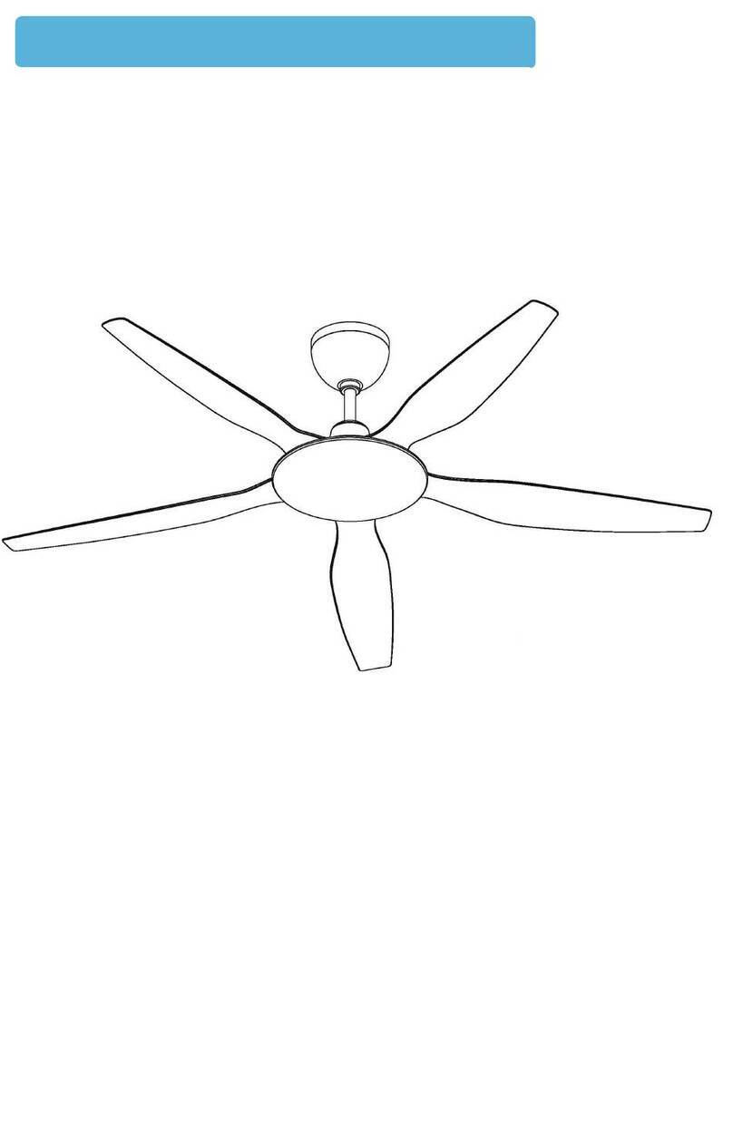
Parts and accessories
2
ALL PICTURES SHOWN ARE FOR ILLUSTRATION PURPOSES ONLY. THE ACTUAL PRODUCT MAY VARY DUE TO PRODUCT ENHANCEMENT.
Remote control (1pc)
Rubber pulley flap
(1pc)
Down rod(1pc)
Connector (1pc)
Canopy(1pc)
Canopy screw
(1pc)
Coupling cover(1pc)
Coupling cover
screw(1pc)
Bolt(4pcs)
Nut(s)(4pcs)
Clevis pin(4pcs)
Washer(s)(4pcs)
Spring washer(s)(4pcs)
Receiver(1pc)
Balancing weight
(2pcs)
Balancing clip(1pc)
Fan blade(s)(5pcs)
Fan blade screw(s)(15pcs)
Coupling joint(1pc)
Bottom motor cover(1pc)
Motor assemble(1pc)

IMPORTANT: SWITCH OFF ELECTRICAL MAINS AT THE
MINIATURE CIRCUIT BREAKER BOX.
Installation procedures
Step 1 - Assembly canopy and coupling cover through the down rod.
Step 2 - Remove both sets of clevis pins, nuts, washers, and bolts from the motor
and assemble the joint. Route all wires from the motor assembly through
the down rod. Place down rod to coupling with bolts, washers, nuts, and
tighten them firmly then insert the clevis pins.Step 2 -
3
ALL PICTURES SHOWN ARE FOR ILLUSTRATION PURPOSES ONLY. THE ACTUAL PRODUCT MAY VARY DUE TO PRODUCT ENHANCEMENT.

Step 3 - Remove the clevis pin, nut, washer, and spring washer, from the bolt, and
Installation procedures
4
ALL PICTURES SHOWN ARE FOR ILLUSTRATION PURPOSES ONLY. THE ACTUAL PRODUCT MAY VARY DUE TO PRODUCT ENHANCEMENT.
remove the bolt and rubber pulley from the down rod. Place rubber pulley
onto ceiling fan hook, insert flap to rubber pulley, and align holes. Push the
bolt from one side of the flap through the rubber pulley to the other side of
the flap. Place washer, and spring washer through the bolt, tighten the nut,
and push the clevis pin into the hole found on the threaded end of the bolt.

Installation procedures
Step - 4 Tie safety wire across the hook as shown
Step 5 - Firmly screw the safety wire with the spring washer onto the down rod
5
ALL PICTURES SHOWN ARE FOR ILLUSTRATION PURPOSES ONLY. THE ACTUAL PRODUCT MAY VARY DUE TO PRODUCT ENHANCEMENT.

Step 6 - Wire up wires as shown
Installation procedures
6
ALL PICTURES SHOWN ARE FOR ILLUSTRATION PURPOSES ONLY. THE ACTUAL PRODUCT MAY VARY DUE TO PRODUCT ENHANCEMENT.
To MOTOR
Red
Pink
Gray
EARTH(Green/Yellow)
NEUTRAL
(Blue)
LIVE
(Brown)

Circuit diagram
Installation procedures
Step 7 - Tighten the canopy with the screw provided. Leave a gap of 3mm - 5mm
between the canopy and the ceiling.
7
ALL PICTURES SHOWN ARE FOR ILLUSTRATION PURPOSES ONLY. THE ACTUAL PRODUCT MAY VARY DUE TO PRODUCT ENHANCEMENT.
RECEIVER
MOTOR
RED
BLACK
RED RED
PINK PINK
GRAY GRAY
L
NYELLOW/GLEEN
YELLOW/GLEEN
BLUE
WHITE
BLUE
WHITE
Leave a 3mm to 5mm gap
between the ceiling and the canopy.

Fan blades installation procedures
Step 8 - Tighten the fan blades with the screws provided. Each blade uses 3 pieces of
screws and 3 washers.
Step 9 - Ensure screws (15pcs) for securing fan blades are tightly screwed. Each
fan blade requires 3 screws and 3 washers.
8
ALL PICTURES SHOWN ARE FOR ILLUSTRATION PURPOSES ONLY. THE ACTUAL PRODUCT MAY VARY DUE TO PRODUCT ENHANCEMENT.
1
2

2 X 1.5V AAA batteries are provided. Insert batteries into the remote control.
Remote control
1) Switch o
Switch on the power supply to the fan.
ff the power supply to the fan.
3) Long press on button within 10 seconds.
4) When beep sound is heard, pairing is complete.
9
ALL PICTURES SHOWN ARE FOR ILLUSTRATION PURPOSES ONLY. THE ACTUAL PRODUCT MAY VARY DUE TO PRODUCT ENHANCEMENT.
Fan on / off button
Light on / off button
Timer buttons
1H-Fan off after 1 hour
2H-Fan off after 2 hours
4H-Fan off after 4 hours
6H-Fan off after 6 hours
8H-Fan off after 8 hours
Speed 1 low speed
Speed 9 high speed
The pairing of remote control and receiver

Power supply connections
Reminder
MCB Fuse box
on/off switch
Maintenance
Due to the fan’s natural movement, connections may get loose after a period of usage,
to ensure proper and safe usage, it is highly recommended to inspect and tighten
all connections every 6 months.
Cleaning your fan periodically will prolong its new appearance. Basic cleaning
procedures are as follows:
1) Use only water. NO detergent, corrosive acidic solution.
2) Use only a soft damp cloth to clean the fan.
3) No lubricating oil on the fan’s spare parts.
10
ALL PICTURES SHOWN ARE FOR ILLUSTRATION PURPOSES ONLY. THE ACTUAL PRODUCT MAY VARY DUE TO PRODUCT ENHANCEMENT.
: USE ONLY NSB FAN, SPECIFIC REMOTE CONTROL TO CONTROL
FAN’S SPEED. DO NOT CONNECT THE FAN TO THE DIMMER
SWITCH OR WALL REGULATOR.

NEO
AC
11
ALL PICTURES SHOWN ARE FOR ILLUSTRATION PURPOSES ONLY. THE ACTUAL PRODUCT MAY VARY DUE TO PRODUCT ENHANCEMENT.
220V-240V~50Hz
More than 1 meter from the wall
2.5 meters above the ground

How to use balancing kit
PREFACE
Fan wobble, may be due to irregular
fan blades and/or fan blades
holder. Improper assembly may
also cause the ceiling fan to wobble.
This balancing kit can be used to
rectify wobbling problems.
Dynamic blade balancing kit for ceiling fan.
.
holders are bent and that none of the fan blades are out of position. A correction
to the motor housing.
can be made by bending the fan blade holder back into position gently.
4. Use a measuring tape to check the blade tracking. Put yard tape up against
the ceiling vertically and against the outside leading edge of a fan blade. Note
the distance of the ceiling. Turn the blades slowly and carefully by hand to check
the remaining blades. If the fan blades are not in alignment, the blade holder
may be gently bent up or down to be in line with other fan blades.
5. Please take note that the above-mentioned method of fan blade correction is
not applicable to all fan blade holders.
After following all steps and if the wobbling problem is not solved, a dynamic balancing
kit is needed to rectify the problem. Please follow the procedures listed below:
• Turn on the ceiling fan and adjust the speed control (usually high speed) setting to
the speed which created the greatest wobble.
• Turn off the ceiling fan, select one of the blades, and place the balancing clip on it,
halfway between the fan blade holder and the tip of the fan blade.
• Turn on the ceiling fan, and see if the wobble improves or worsens. Turn off the fan
again and move the balancing clip to another fan blade and test again. Repeat this
process with all fan blades and then note the fan blade that causes least wobble.
• Move the balancing clip to the fan blade which shows the least wobble or shows the
most improvement. Move the balancing clip in and outward on this fan blade and
improvement.
• Remove the balancing clip and stick the balancing weight on top of the fan blade,
along the center line near the point where the clip was positioned.
Caution: stay clear of fan blades, if the balancing clip for any reason is not secure
may cause injury(s).
12
ALL PICTURES SHOWN ARE FOR ILLUSTRATION PURPOSES ONLY. THE ACTUAL PRODUCT MAY VARY DUE TO PRODUCT ENHANCEMENT.

13

14

NSB FAN
NSB Home Appliances Sdn Bhd
Careline number: -
1300 880 672 (NSB)
www.nsb.com.my
If technical assistance is required, please contact NSB FAN customer service.
Table of contents
Other NSB FAN Fan manuals

NSB FAN
NSB FAN CUPID Installation and operating instructions

NSB FAN
NSB FAN Ovio+ 60 User manual

NSB FAN
NSB FAN KELLY Installation and operating instructions

NSB FAN
NSB FAN TEEGA User manual

NSB FAN
NSB FAN X LED User manual

NSB FAN
NSB FAN ALOHA User manual

NSB FAN
NSB FAN ANISE Installation and operating instructions

NSB FAN
NSB FAN JUMBO User manual

NSB FAN
NSB FAN Jaya Deluxe User manual

NSB FAN
NSB FAN MOORE User manual