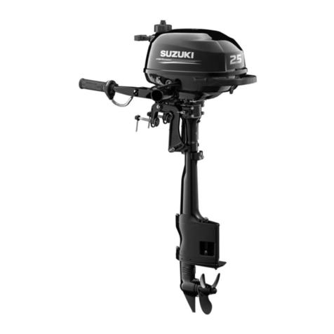
NSK Primado 2 User manual

Total Surgical System
Motor
OM-SE0029E 001

1
Read these precautions carefully and use only as intended or instructed.
Safety instructions are intended to avoid potential hazards that could result in personal injury or damage to the device. Safety instructions are classified as
follows in accordance with the seriousness of the risk.
This product is the Motor used with our surgical control unit Primado2.
Prior to use, read this Operation Manual carefully and understand operating precautions, operating methods and maintenance guidelines so that you can use it
for many years to come through a correct use. Keep this Operation Manual within easy reach.
Precautions for handling and operation
Class
Degree of Risk
DANGER
Hazard that could result in personal death or serious injury if the safety instructions are not correctly
followed.
WARNING Hazard that could result in serious injury or damage to the device if the safety instructions are not correctly
followed.
CAUTION
Hazard that could result in light or moderate injury or damage to the device if the safety instructions are
not correctly followed.
NOTICE General product specification information highlighted to avoid product malfunction and performance
reduction.

2
Intended Use
The Primado 2 is an AC-electrically powered total surgical system that is intended for cutting, drilling, sawing, and otherwise manipulating soft tissue,
hard tissue, bone, bone cement, prosthesis, implant, and other bone related tissue in a variety of surgical procedures, including but not limited to Cranial
(Craniofacial/Maxillofacial), ENT, Endoscopic/Arthroscopic, Neuro, Orthopedic, Spinal, and General surgical procedures.
DANGER
Do not use this system in a room where there is danger of explosion or in the vicinity of flammable substances. It is especially important not to use this
system on a patient to whom a flammable anesthetic agent (dinitrogen monoxide) has been administered.
Never disassemble or modify the product. Personal injury, electric shock or fire may result.
WARNING
When operating the product always consider the safety of the patient.
This is a medical system ; do not allow anybody to use it other than surgeons who are familiar with the procedures. Use this system in accordance with its
intended use and proper method of use.
This product may be affected when used in rooms with electromagnetic interference and portable or mobile RF communication equipments. Do not use this
product around any equipment that generates electromagnetic waves such as an ultrasonic generator and electrical scalpel. In case equipment generating
electromagnetic waves are used around this product, turn off the Control Unit.

3
CAUTION
U.S. Federal law restricts this device to sale by or on the order of a licensed physician.
The applicable Attachment/Handpiece for cutting implants is Metal Cutting Handpiece 200.
Be sure to read this manual prior to use to become completely familiar with the function of each part.
The Motor (separately sold) is not sterilized before delivery. Therefore, be sure to sterilize it prior to use.
Be sure to operate the Attachment/Handpiece connected to Motor and Control Unit prior to use. Even if only a slightly abnormal condition such as vibration,
abnormal sound, and heat generation is detected, stop use and contact your dealer.
Do not subject this product to strong impacts such as dropping it on the floor. Personal injury, abnormal heating and fire may result caused by the internal
damage.
Do not disconnect the Motor Cord from the Motor. It may cause failure.
Do not clean the product with solvents such as thinner or benzine solution. Discoloration or deformation may result.
Regarding the operation time of the Motor, follow the specification table in Step “7. Specifications”. Continuous use of the Motor for a prolonged period
might cause overheating, which can cause an accident.
The temperature of the Motor and Control Unit mounting parts may reach up to 60˚C depending on the environment.
NOTICE
The user shall be responsible for maintenance and operation.

4
1-1 Motor
P200-HMH, P200-SMH, P200-BMH
P200-HMH-HS, P200-SMH-HS, P200-BMH-HS (Motor with Hand Control)
1) Hand Switch* 2) Adjustable Lever*
3) Safety Lock* 4) Motor Cord Plug * Motor with Hand Control only.
2)
1) 3)
ON
OFF 4)
1Part Names

5
1-2 Wire Pin Driver
P200-WPD
1) Trigger (Upper) (A) 2) Safety Lock 3) Trigger (Lower) (B)
4) Mounting/Removal Button 5) Motor Cord Plug
2)
3)
1) 4) 5)

6
2-1 Connection to the Control Unit
By matching the mark on the Motor Cord Plug and the mark on the Motor Connector (A or B) at the
front of the Control Unit, plug the Motor into the Connector all the way.
2How to Connect Each Component
* To disconnect the Motor, hold the Motor Cord Plug and pull it out with a straight movement.
Fig. 1
Refer to the Operation Manuals of Primado2 and Attachments/Handpieces.
CAUTION
There are two Motor Connectors. By connecting two Motors to the two connectors,
you can select the one you want to use by the Motor Select Button of the Control
Unit. (However, both Motors cannot be operated simultaneously.) The selected
Motor can be confirmed in the Main Panel of the Control Unit. Refer to the Operation
Manual of the Control Unit for detail.
CAUTION
Mark
Mark
Motor Cord Plug

7
Whenever you use two Motor Connectors alternately, be sure to confirm which Motor is under operation.
Connect or disconnect the Motor Cord only after turning OFF the Control Unit.
Do not connect the Motor to Control Units other than Primado2. Otherwise, it could deform the Motor Connector and cause failure.
If the Motor Cord cannot be connected to the Control Unit easily, do not insist. Deformation or cracks might occur. A foreign substance
might be obstructing the connection or the connection portion might be deformed. Contact your dealer.
Whenever connecting/disconnecting the Motor with Hand Control and Wire Pin Driver, be sure to turn OFF the Control Unit.
When connecting/disconnecting the Motor, do not rotate the Motor Cord Plug. Otherwise, the inside pins might become damaged,
leading to failure.
Do not connect/disconnect the Motor Cord with wet hands; otherwise, an electric shock might occur.
CAUTION

8
2-2 Mounting of the Attachment/Handpiece
P200-HMH and P200-HMH-HS Attachments/Handpieces
<Mounting>
1) Push the Attachment/Handpiece into the Motor straight.
2) Rotate the Attachment/Handpiece rightward or leftward so that the Alignment Pin of the Motor
(Fig. 2) matches the hole of the Attachment/Handpiece with a clicking sound to connect firmly.
<Removing>
Pull out the Attachment/Handpiece from the Motor straight. Fig. 2
Attachment /
Handpiece
Motor
Alignment Hole Alignment Pin
Whenever mounting/removing the Attachment/Handpiece, be sure to switch OFF the Safety Lock of the Wire Pin Driver/Motor with Hand
Control.
Prior to mounting/removing the Attachment/Handpiece, remove the Bur or Blade. Otherwise, injury might occur.
After mounting the Attachment/Handpiece, confirm that the Attachment/Handpiece and Motor are connected properly.
CAUTION

9
P200-SMH and P200-SMH-HS Attachments/Handpieces
<Mounting>
1) Push the Attachment/Handpiece into the Motor straight.
2) Align the ' ' Symbol of the Attachment/Handpiece and ' ' Symbol of the
Motor (Fig. 3), then push the Attachment/Handpiece in until it clicks to connect firmly.
<Removing>
Pull out the Attachment/Handpiece from the Motor straight.
P200-BMH and P200-BMH-HS Attachments/Handpieces
<Mounting>
1) Push the Attachment/Handpiece into the Motor straight.
2) Rotate the Attachment/Handpiece rightward or leftward so that the Alignment Pin of the Motor
(Fig. 4) matches the hole of the Attachment/Handpiece with a clicking sound to connect firmly.
3) Tighten the Removal Ring of the Attachment/Handpiece manually to fix it firmly.
<Removing>
Loosen the Removal Ring and pull out the Attachment/Handpiece from the Motor straight.
Fig. 3
Fig. 4
Attachment /
Handpiece
Motor
Symbol
Symbol
CLOSE
OPEN
Attachment / Handpiece
Motor
Alignment Hole Alignment Pin

10
P200-WPD Attachments/Handpieces
<Mounting>
Insert the Attachment straight into the Motor until it clicks.
<Removing>
Pull the Attachment straight out while pressing the Mounting/Removal Button
of the Motor.
Fig. 5
Motor
Attachment /
Handpiece Mounting / Removal
Button

11
Follow the check list below before use. If any abnormalities are found, stop using the product immediately and contact your dealer.
1) Check for any abnormalities or damage on the outer surface and for any damage or deformation on the Pins in the Motor Cord Plug.
2) Check that the Motor can be securely connected to the Control Unit.
3) Check the following points before operating the Motor.
Ř:KHWKHUWKH$GMXVWDEOH/HYHURIWKH+DQG6ZLWFKVOLGHVVPRRWKO\
Ř:KHWKHUWKH6DIHW\/RFNVRIWKH+DQG&RQWURODQG:LUH3LQ'ULYHUVOLGHVPRRWKO\
4) Depress the Pedal of the Foot Control to check for any abnormal vibration, noise or heating in the Motor. Check in the Main Panel of the Control Unit that the
rotational speed can reach the maximum speed you have set.
5) Check that Forward, Reverse, and Oscillate (P200-WPD only) Modes operate normally.
6) Mount the Attachment/Handpiece to the Motor to check their secure connection.
* If any abnormalities are found, stop using the product immediately and contact your dealer.
* Operate the product if none of the above abnormalities are present.
* When checking Attachments/Handpieces before treatment, refer to the Operation Manual of each Attachment/Handpiece.
3Check before Operation

12
This can be done in three ways: by the Motor with Hand Control, the Primado2 Wire Pin Driver or the Foot Control.
4Operation
The Motor with Hand Control and the Primado2 Wire Pin Driver can also be operated by the Foot Control. Connect it with the Foot Control
and depress the Pedal. The Motor will work in the normal mode of the Foot Control, regardless of the Hand Control.
If operating the Motor only with the Motor with Hand Control and the Primado2 Wire Pin Driver, it is recommended to disconnect the Foot
Control from the Control Unit. Alternatively, set the Foot Control to OFF by the Foot Control ON/OFF Button (to disable the Foot Control).
Refer to the Operation Manuals of Primado2 and Attachments/Handpieces.
The Hand Switch of the Motor with Hand Control and the Pedal of the Foot Control are variable. The rotational speed increases/
decreases within the preset rotation range, depending on the extent/duration of depressing.
CAUTION

13
When using the Motor with Hand Control
1) Confirm that the Safety Lock of the Hand Control is OFF.
2) Slide the Adjustable Lever to the desired length.
3) Hold the Hand Switch and slide the Safety Lock to ON (Fig. 6).
4) Depress the Hand Switch to start the Motor. When the Hand Switch is depressed or released, there
is a short alarm sound.
When the Reverse Mode has been selected, the Bur rotates in reverse. During the reverse rotation in
this Mode, the alarm continues to sound.
OFF ON
Fig. 6
When operating the Safety Lock, be sure to hold the lever with your finger. If operating it without holding the lever, the lever might
inadvertently be depressed when the Safety Lock is being turned ON/OFF, thereby triggering a rotation of the Motor. This might cause an
accident.
CAUTION
Adjustable Lever
Safety Lock

14
When using the Primado2 Wire Pin Driver
1) Confirm that the Safety Lock is working ( / ).
2) Release the Safety Lock of the Wire Pin Driver from LOCK and switch it to Reverse OFF (FWD/ ) or
Both ON (FWD/REV).
Ř ,QWKH5HYHUVH2))(FWD/ ) Mode, when depressing the lower Trigger (B) of the Wire Pin Driver,
the Attachment/Handpiece rotates forward. When depressing the Trigger or releasing it, a short
alarm sounds. In this Mode, the upper Trigger (A) is locked, and therefore the Trigger cannot be
depressed (i.e., it cannot be put into operation).
Ř,QWKH%RWK21):'5(90RGH
- When depressing the lower Trigger (B), the Attachment/Handpiece rotates forward. When depressing the Trigger or releasing it, a short alarm
sounds. When depressing the upper Trigger (A), the Attachment/Handpiece rotates in reverse. During the reverse rotation, the alarm continues to
sound.
- When depressing both the upper (A) and lower(B) Triggers simultaneously, the forward and reverse rotations of the Attachment/Handpiece are
repeated alternately (i.e., the rotation direction oscillates). The rotation direction changes at every 360 degrees of rotation. If one of the Triggers has
been depressed earlier, it will take priority in the function and rotation direction. When the other Trigger is depressed with the first Trigger already
functioning, the forward and reverse rotations will start to alternate: namely, Oscillate Mode will start.
㹀
㸿
Fig. 7
Safety Lock

15
When Using the Foot Control
1) When depressing the Pedal of the Foot Control, the Motor starts to operate. When depressing the
Pedal or releasing it, a short alarm sounds.
2) In the Reverse Mode, the Bur starts rotating in reverse. During this reverse rotation, the alarm
continues to sound.
Trigger
Upper (A)
Lower (B)
Upper and Lower depressed simultaneously (A B)
Rotation Direction
Reverse Rotation
Forward Rotation
Oscillation (Forward and reverse rotations are repeated alternately)
Fig. 8
The Wire Pin Driver operates in the rotation direction set not by the Control Unit but by the Wire Pin Driver.
CAUTION
Pedal

16
3) Push the Foot Control Button (Multiple Model: blue, silver and green buttons; Single Model: silver button) to set the Control Unit to the pre-determined
function. For any further information, refer to " 6-4 Setting Up the Foot Control " in Primado2 Operation Manual.
Fig. 9
Before using the Foot Control Button, be sure to confirm what function is assigned to that Button in the Sub Panel.
CAUTION
Foot Control Button (Blue) Foot Control Button
(Silver)
Foot Control Button
(Green)
Pedal

17
5-1 Preparation prior to washing
1) Remove the Attachment/Handpiece from each Motor.
2) Disconnect the Motor Cord from the Control Unit.
3) Check for any damage or deterioration on the outer surface of each Motor or Motor Cord, and for any deformation or loss of each connecter pin.
5-2 Cleaning
1) Wipe stains off the surface of the Motor (including the Motor Cord) thoroughly using a lint-free cloth moistened with neutral detergent for medical use or
a non-metallic brush.
2) Remove the detergent solution using a lint-free cloth moistened with distilled, deionized or demineralized water.
Perform cleansing and sterilization after every use.
Be sure to clean and sterilize the Motor after use. Unremoved blood may result in product failure due to the internal blood coagulation.
In order to prevent infection, put on a mask, rubber gloves and a pair of protection goggles.
CAUTION
5Cleaning / Sterilization

18
5-3 Washing and disinfecting
The Motor can be washed via Thermo Disinfector.
If a Thermo-Disinfector is not available, proceed to “5-4 Sterilization” below.
The following conditions are recommended for Thermo Disinfector: (It is recommended to use a thermo disinfector compatible with ISO 15883)
a. Cleaning: at 45˚C for 3 minutes
b. Intermediate rinse: At least 1 minute (using distilled, deionized or demineralized water)
c. Thermal disinfecting: at 93˚C for 5 minutes (using distilled, deionized or demineralized water)
d. Drying: at least 10 minutes
Prior to use of a Thermo Disinfector, read the Thermo Disinfector Operation Manual carefully.
Do not use a chlorinated cleaner.
Do not clean the Motor by an ultrasonic cleaning apparatus.
After cleaning and prior to sterilization, check the Motor in the same method as in Step “3. Check before Operation”.
The P200-WPD is made out of aluminum, therefore take special precaution to always use a PH neutral detergent compatible with
aluminum, when washing it in a Thermo Disinfector.
CAUTION

19
1) Place it in a Primado Sterilization Cassette.
2) Autoclave under the following conditions;
Ř3UHYDFXXP$XWRFODYHDWņ&IRUPLQXWHVRUORQJHU
Ř*UDYLW\GLVSODFHPHQW$XWRFODYHDWņ&IRUPLQXWHVRUORQJHU
5-5 Storage
Store the sterilized Motor in a place where it can be kept sterile until the next use.
5-4 Sterilization
We verify the validity of sterilization in the following conditions.
The sterilization parameters are indicated for sterilization and immediate use only.
Do not soak the Motor into water, or failure might occur.
The Motor is not suitable for EOG sterilization.
Sterilize the Motor after each patient.
Do not clean the Motor by a washer sterilizer.
The Motors do not require lubrication. Never lubricate them.
When cleaning or sterilizing Attachments/Handpieces, refer to the Operation Manual of each Attachment/Handpiece.
CAUTION
Table of contents
Other NSK Engine manuals
Popular Engine manuals by other brands
Briggs & Stratton
Briggs & Stratton 10T600 Series Illustrated parts list
Briggs & Stratton
Briggs & Stratton 100900 Operating and maintenance instructions

Kohler
Kohler KDI 2504 M-MP owner's manual
Siemens
Siemens SIMOTICS S-1FT2 operating instructions
Briggs & Stratton
Briggs & Stratton 217800 Series Illustrated parts list
Bison
Bison 170F user manual
SIMONINI FLYING
SIMONINI FLYING Victor 2 Operator's manual
Sauer Danfoss
Sauer Danfoss DH Series Assembly and Test Procedures
Maverick
Maverick LX10-3S100 Instruction

Robin
Robin EH18V OHV Service manual

Jet Central
Jet Central Rabbit Operation and maintenance manual

Robin America
Robin America Engine EX40 parts manual

