NSK VOLVERE i7 User manual


1
English
Table of Contents
1. Users and Indications for Use..................................................................................................................2
2. Precautions for handling and operation ...................................................................................................2
3. Package Contents..................................................................................................................................6
4. Parts Names..........................................................................................................................................7
4-1 Control Unit.....................................................................................................................................7
4-2 Foot Control ....................................................................................................................................7
5. Preparations for Use ..............................................................................................................................8
5-1 Connecting the Power Cord..............................................................................................................8
5-2 Connecting the Foot Control.............................................................................................................8
5-3 Connecting the Motor Handpiece......................................................................................................8
5-4 Attaching / Removing the Handpiece.................................................................................................8
5-5 Attaching / Removing a Bur..............................................................................................................9
6. Check Before Use ................................................................................................................................10
7. Operation Procedure............................................................................................................................10
7-1 Operation......................................................................................................................................10
7-2 Control Sounds and Operation Sounds............................................................................................11
7-3 Memory Function ..........................................................................................................................11
7-4 Protection Circuit...........................................................................................................................11
8. Post-use Maintenance .........................................................................................................................12
8-1 Cleaning and Replacing the Chuck .................................................................................................12
8-2 Cleaning the Control Unit, Motor Handpiece, and Foot Control ..........................................................13
9. Maintenance .......................................................................................................................................13
9-1 Disconnecting and Connecting the Motor and Motor Cord................................................................13
9-2 Replacing the Carbon Brush...........................................................................................................13
10. Periodical Maintenance Checks ............................................................................................................14
11. Troubleshooting ...................................................................................................................................14
11-1 Errors .........................................................................................................................................14
11-2 Problems and Solutions ...............................................................................................................15
12. Specifications......................................................................................................................................16
12-1 Specifications..............................................................................................................................16
12-2 Classification of Equipment ..........................................................................................................17
13. Symbols..............................................................................................................................................17
14. Warranty .............................................................................................................................................17
15. Option Parts List ..................................................................................................................................17
16. Spare Parts List ...................................................................................................................................18
17. Disposing of the Product ......................................................................................................................18
Thank you for purchasing the VOLVERE i7.
Please read this Operation Manual carefully before use for operating instructions and care and maintenance guidelines
so that you can use it for many years to come through correct use. Keep this Operation Manual within easy reach of
users for future reference.
English
English

2
DANGER
• Never disassemble or modify the product. Doing so may lead to injury, electric shock, or fire.
• Do not handle the Power Cord or other cords with wet hands. Doing so may lead to electric shock.
• If you notice deformation or partial discoloration in the exterior of the Control Unit or Motor Handpiece, cease
operation immediately and contact your Authorized NSK Dealer. Failure to do so may lead to electric shock or fire.
• Do not use or leave the product in locations subject to high temperatures, such as areas subject to strong direct
sunlight, cars left under hot sun, next to fires, or near a heater. Doing so may lead to overheating or ignition due
to malfunctions in the internal circuitry.
• Do not pass the cords near a gas burner. Doing so may cause the cords to burn and become damaged. Damaged
cords must be replaced with new cords rather than being repaired, as they may cause fires or electric shock due
to a short circuit.
• Please read these precautions carefully and use only as intended or instructed.
• Safety indicators are intended to avoid potential hazards that could result in personal injury or damage to the
product.
Safety instructions are classified as follows in accordance with the seriousness of the risk.
Hazard that could result in personal death or serious injury if the safety instructions are not
correctly followed.
DANGER
Hazard that could result in serious injury or damage to the device if the safety instructions are
not correctly followed.
WARNING
Hazard that could result in light or moderate injury or damage to the device if the safety
instructions are not correctly followed.
CAUTION
General product specification information highlighted to avoid product malfunction and
performance reduction.
NOTICE
Class Degree of Risk
Users: Dental Technicians and Dentists
Indications for Use: For use in Dental Laboratories for cutting and polishing.
1Users and Indications for Use
2Precautions for handling and operation

3
English
WARNING
• This product is only for use in Dental Laboratory work. Do not use it for medical treatment.
• The system may present a possibility of malfunction when used in the presence of an electromagnetic
interference wave. Do not install the system in the vicinity of any device which emits magnetic waves. Turn off the
Main Power of the system as an ultrasonic oscillation device or an electrode knife is located close to the vicinity
of use.
• Use of an E-type Handpiece from a manufacturer other than NSK may lead to reduced rotation/torque
performance or generation of heat. Pay attention when using such a handpiece.
• Never use a Power Cord other than a genuine NSK Power Cord. Doing so may lead to an inability to maintain
quality.
• Do not use the product adjacent to or stacked with another device. If it is necessary to use the product adjacent
to or stacked with another device, verify that the product and the other device operate correctly before using
them.
• If the product overheats or smells of burning, immediately turn the power OFF, disconnect the Power Cord, and
contact your Authorized NSK Dealer.
• If you notice vibrations, generation of heat, abnormal sounds, or problems with the power supply, etc., cease
operation immediately and refer to "11. Troubleshooting".
If an inspection indicates that the cause of the problem is a part that cannot easily be replaced or the cause of
the problem cannot be identified, contact your Authorized NSK Dealer.
• Keep away from explosive substances and flammable materials.
• Conform to the allowable rotation speed specified by the manufacturer or distributor of the bur. Failure to do so
may lead to injury due to the bur breaking and scattering or the Motor Handpiece vibrating violently.
• Do not use burs that are unstable, bent, damaged or have wear on the shank. Doing so may lead to injury due to
the bur breaking or suddenly releasing from the chuck, etc.
• When using a disk, use it at as low a rotation speed as possible to prevent it from scattering due to breaking, etc.
• Since a grindstone may be unbalanced, even if new, make sure to perform dressing before using it. Using an
unbalanced grindstone may lead to injury due to it breaking and scattering.

4
CAUTION
• The product must be used by a person certified to perform dentistry, such as a Dental Technician or Dentist, in a
dental clinic, hospital or other dental institution.
• When using the product, for health and safety purposes, wear eye protectors, use a grindbox and a vacuum
system, etc.
• Read this Operation Manual before use to fully understand the product functions.
• Do not subject the product to strong shocks (such as by dropping it). Doing so may lead to electric shock or
malfunction.
• Clean the Motor Handpiece on a timely basis. For information on cleaning, refer to "8. Post-use Maintenance" in
this Operation Manual.
• Do not place the product next to a heat source such as a heater. Doing so may lead to discoloration or
deformation.
• Do not lubricate the Motor Handpiece. Doing so might cause it to generate heat or malfunction.
• Do not clean, soak, or wipe the product with electrolyzed oxidizing water (acidic water or strongly acidic water),
strongly acidic or alkaline agents, solutions including chlorine, or solvents such as benzine or thinner.
• Do not use the product in locations where static electricity is emitted, as this may damage its protective
mechanisms.
• Do not expose to water or liquids.
• Use the Control Unit in an environment between 0 and 40 °C and with no condensation. Condensation may lead
to electric shock due to a short circuit.
• When a bur is rotating, do not turn the bur lock ring in the OPEN direction. Doing so will cause the Motor
Handpiece to break. Replace a bur only after rotation has completely stopped.
• When using a bur with a large cutting blade (4 mm or larger in diameter), use it at as low a rotation speed as
possible.
• Avoid using the product with loads that will cause the protection circuit to operate where possible. Failure to do
so may cause motor heat generation, bur damage and early wear in the Motor Handpiece.
• If disinfectant, water, or saline, etc. becomes attached to the Control Unit or Motor Handpiece, turn the power
OFF, wipe them clean with a damp cloth, and then wipe them well with a dry cloth.
• Do not cover the air vents on the rear of the product.
• Make sure to perform periodic inspections of the product and its parts.
• It is recommended that you prepare a spare product just in case it breaks during use, etc.
• Portable and mobile RF communication devices may affect the operation of this product.
• If accessories or cables other than those sold as replacement parts by the manufacturer are used, the EMC
performance of the product may be reduced (emissions may increase or immunity may decrease).
• Turn the Power OFF after use. When not using the product for an extended period of time, disconnect the Power
Cord from the outlet.
• Install the product so that the Power Cord can be disconnected from the outlet immediately if a problem occurs,
to cut it off from the commercial power supply. Do not place any objects within 15 cm of the Power Cord.
• When disconnecting the Power Cord, hold the cord by its plug and pull the plug out. Holding and pulling the cord
may snap the wiring in the cord.
• When attaching a bur, confirm that there is no debris or foreign material on the shank. If foreign material, etc.
enters the chuck, the bur may break or the chuck may weaken.
• Users are responsible for the operational control, maintenance and continual inspection of the product.
• When the product has not been used for a long time, perform an operational check for abnormalities such as
rattling, vibrations, abnormal sounds, and generation of heat.

5
English
NOTICE
• Keep a cutting bur or test bur attached even when the product is not in use.
• Units to be send back to manufacturer in case of breakdown.
• No special training is required for this device.
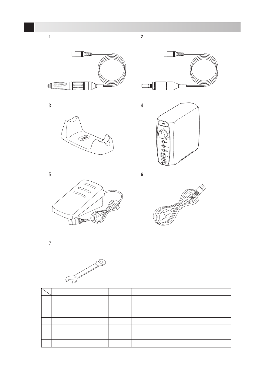
6
1
2
3
4
5
6
7
Name
Motor Handpiece
E-Type Motor
Handpiece Stand
Control Unit
Foot Control
Power Cord
Spanner Wrench
Remarks
Included in the Standard Set "VOLVERE i7 RM"
Included in the Standard Set "VOLVERE i7 E"
-
-
-
-
-
Quantity
1
1
1
1
1
1
1
3Package Contents
7
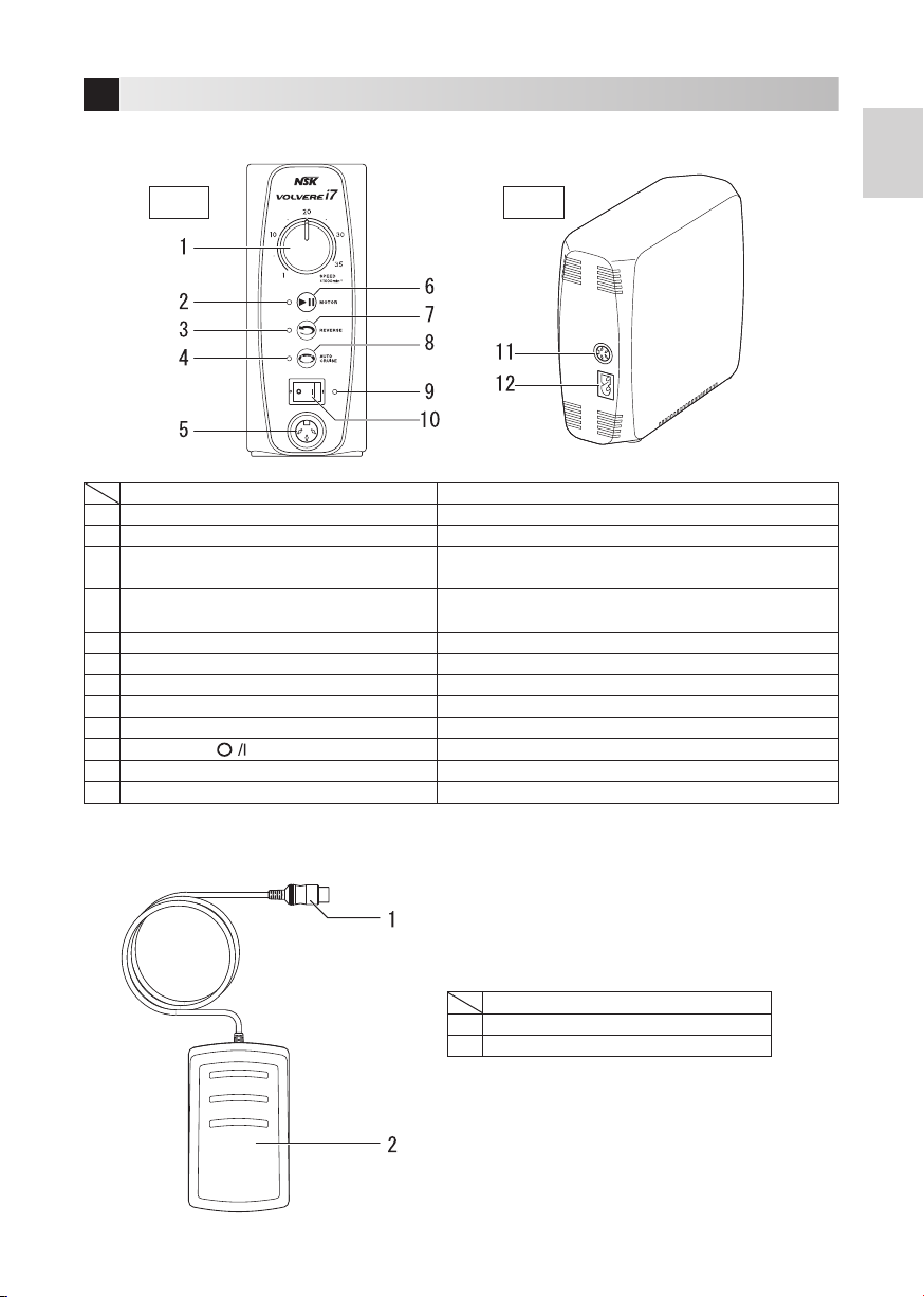
English
4-1 Control Unit
Name Function
1 Speed Control Knob (SPEED) Adjusts the bur rotation speed.
2 ON-OFF LED Turns on when the bur rotation is activated.
3 REVERSE LED Turns on when rotating in reverse. Turns off when rotating in
the forward direction.
4 AUTO CRUISE LED Turns on when the product is in the auto cruise standby mode.
Flashes when the auto cruise function is operating.
5 Motor Cord Socket Connect the Motor Handpiece here.
6 ON-OFF Key (MOTOR) Switches the bur rotation on and off.
7 Forward/Reverse Selector Key (REVERSE) Switches the rotation direction of the bur.
8 AUTO CRUISE Key (AUTO CRUISE) Switches to the auto cruise standby mode.
9 Power LED Turns on when the power is turned ON.
10 Power Switch ( ) Switches the power ON and OFF.
11 Foot Control Cord Socket Connect the Foot Control here.
12 Inlet Connect the Power Cord here.
4Parts Names
4-2 Foot Control
Name
1 Foot Control Cord Plug
2 Control Pedal
Front Rear

8
Fig. 1
Fig. 2
Fig. 3
Positioning
5-1 Connecting the Power Cord
Align the shape of the Power Cord Plug with the inlet on the rear of the
Control Unit, and fully insert it (Fig. 1).
When disconnecting the Power Cord, firmly grip the Control Unit and the
Power Cord plug, then pull the plug straight out.
5-2 Connecting the Foot Control
Align the positioning of the Foot Control Cord Plug (the mark) with the
Foot Control Cord Socket on the rear of the Control Unit, and fully insert it
(Fig. 2).
When disconnecting the Foot Control cord, firmly grip the Control Unit and
the Foot Control Cord Plug, then pull the plug straight out.
5-3 Connecting the Motor Handpiece
Align the positioning of the Motor Handpiece cord plug with the Motor
Cord Socket on the front of the Control Unit, and fully insert it (Fig. 3).
When disconnecting the Motor Handpiece cord, firmly grip the Control
Unit and the Motor Handpiece cord plug, then pull the plug straight out.
5Preparations for Use
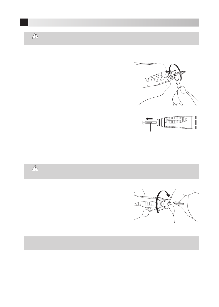
5-4 Attaching / Removing the Handpiece
•When disconnecting a cord, make sure to grip it by the plug. Removing by pulling the cord may
cause it to break.
CAUTION
•Attach or disconnect the Handpiece only after the power has been turned OFF and the bur has
completely stopped rotating.
•After attaching the Handpiece, make sure the Handpiece is securely connected to the Motor.
CAUTION
Motor Handpiece (VOLVERE i7 RM)
Removing:
Turn the bur lock ring of the Handpiece from the LOCK position
further towards the LOCK direction (Fig. 4).
Attaching:
Turn the bur lock ring of the Handpiece in the OPEN direction.
•This product can also be connected to motors for NSK VOLVERE Vmax (GX35RM & SCD, GX35M
& SCD).
NOTICE
Fig. 4

9
Fig. 6
Fig. 7
English
5-5 Attaching / Removing a Bur
Removing:
1) Turn the bur lock ring in the OPEN direction shown in the Fig. 7
until it clicks to open the chuck.
2) Pull out the bur.
Attaching:
1) Fully insert the bur.
2) Turn the bur lock ring in the LOCK direction shown in the Fig. 7 until it clicks to close the chuck.
After attaching the bur, pull it back and forth to confirm that it is connected securely.
E-type Motor (VOLVERE i7 E) (Example: Attaching / Removing a VR-EB)
Removing:
Firmly grip the front of the motor and the rear of the Handpiece (option),
and pull them straight out (Fig. 6).
Attaching:
Insert the Handpiece (option) straight into the insertion area of the
motor.
•Do not touch the bur when it is rotating. Doing so may cause injury.
•Never turn the bur lock ring while a bur is rotating.
•Do not rotate the motor without a bur inserted. Doing so may cause the damage to the
Handpiece.
CAUTION
•When attaching the Handpiece to the motor, the screw-
in may suddenly become tight. This is because the motor
transmission clutch of the Motor Handpiece is misaligned. In
this case, forcibly tightening the screw will cause the motor to
break. Loosen the screw, rotate the chuck of the handpiece
or the bur to align the motor transmission clutch, and then
tighten the screw again (Fig. 5).
CAUTION Transmission clutch
Handpiece Motor
Fig. 5
Insertion area
Handpiece Motor
•When the bur lock ring is in the OPEN position, the product will beep and the Motor Handpiece
will not operate.
NOTICE

10
7-1 Operation
1) Insert the Power Cord into a commercial outlet.
2) Switch the Power Switch to the ON (I) position.
The product beeps twice, and the Power LED turns blue.
3) Rotate the bur.
The following two methods are available.
Using the Foot Control
1) Set the Speed Control Knob to a speed within the allowable rotation speed of the bur.
2) Depress the control pedal.
The rotation speed can be finely adjusted according to how far the pedal is pressed down.
To stop rotation of the bur, remove your foot from the control pedal.
Using the Control Unit
1) Turn the Speed Control Knob all the way counterclockwise to set the motor to the minimum speed.
2) Press the ON-OFF Key.
The ON-OFF LED turns on, and the bur rotates.
3) Adjust the rotation speed using the Speed Control Knob.
Adjust the rotation speed within the allowable rotation speed of the bur.
4) To stop rotation of the bur, press the ON-OFF Key again.
Other Functions
Reversing the Bur Rotation
Press the Forward / Reverse Selector Key only after the bur has stopped rotating. The REVERSE LED turns on,
and the bur rotation is switched to Reverse. The bur normally rotates clockwise, and rotates counterclockwise
when Reverse is selected.
To return to forward rotation, press the Forward / Reverse Selector Key again.
Auto Cruise Function
1) Press the AUTO CRUISE Key when the bur has stopped rotating.
The AUTO CRUISE LED turns on, and the product enters the auto cruise standby mode.
2) Depress the Control pedal of the Food Control, and maintain the desired speed (for approx. 2 seconds).
The product beeps twice, and the AUTO CRUISE LED flashes blue. Auto cruise is enabled, and the bur rotates
at the same speed even if you release your foot from the Control pedal.
3) Take either of the following three steps to stop the bur rotation.
• Depress the Control Pedal again
• Press the AUTO CRUISE Key
• Press the ON-OFF Key
The auto cruise standby mode is retained in either case.
4) To cancel the auto cruise standby mode, press the AUTO CRUISE Key again.
7Operation Procedure
6Check Before Use
Inspect the product before use. If you notice a problem such as vibrations, heat generation, or abnormal sounds during
an inspection or use of the product, cease operation immediately and contact your Authorized NSK Dealer.

11
English
7-2 Control Sounds and Operation Sounds
Description LED Sound Remarks
1 Power ON Turns on Two beeps -
2 Button operations Turn on/turn off One beep -
3 Overload warning - Keeps beeping Refer to 7-4 to disable the
overload notification function.
4Auto Cruise ON Flashes Two beeps -
Auto cruise standby mode Turns on One beep -
7-3 Memory Function
The product memorizes its status when the power is turned OFF. That status is recalled the next time the power is
turned ON.
7-4 Protection Circuit
If you operate the motor with a load exceeding the limit or when the
bur
cannot rotate, the product will emit beeps
(overload notification function). The beeping will stop when the load is reduced, but if the overlaod continues the
protection circuit will automatically stop the power supply to the motor to prevent danger and damage to the product.
Disabling the Overload Notification Function (Beeping)
Press and hold the Auto Cruise Key during rotation to disable the overload notification sound.
To activate the notification sound again, repeat the same procedure.
•When the overload notification function is disabled, take care of heat generation due to the motor
overload.
CAUTION
12
8-1-3 Attaching the Chuck
1) Turn the bur lock ring or lever to the OPEN position.
2) Insert the bur in the chuck, then insert the chuck until it stops.
3) Turn the chuck clockwise with your finger until it stops (Fig. 10).
Then lock the bur lock ring to securely hold the bur.
•Neglecting to clean the chuck for a long time is very dangerous because wax, gypsum, etc., will
accumulate in the chuck, causing the bur to be insecure and causing runout.
CAUTION
8-1 Cleaning and Replacing the Chuck
8-1-1 Removing the Chuck
1) Turn the bur lock ring to the OPEN position.
2) Turn the chuck counterclockwise with the spanner wrench
included with the product (Fig. 8).
3) Remove the chuck (Fig. 9).
8-1-2 Cleaning the Chuck
In order to maintain the precision of the chuck, remove it regularly for cleaning with an ultrasonic cleaner, etc. It
is recommended that the chuck is cleaned at least once a week to ensure the product performance and safety.
8Post-use Maintenance
Loosen
Fig. 8
Chuck
Fig. 9
•Make sure to turn the power of the Control Unit OFF before performing maintenance. Failure to
do so may cause unexpected injury.
CAUTION
•Apply a thin layer of oil to the chuck before insertion.
NOTICE
Until it stops
Fig. 10

13
English
•If disinfectant, water, or saline, etc. becomes attached to the Control Unit, Motor Handpiece, or
Foot Control, turn the power OFF. Then wipe wipe them clean with a damp cloth, and wipe them
well with a dry cloth.
CAUTION
8-2 Cleaning the Control Unit, Motor Handpiece, and Foot Control
1) Turn the power of the Control Unit OFF.
2) Remove the Power Cord from the Control Unit.
3) Wipe the surface of the Control Unit, Motor Handpiece, and Foot Control with a damp cloth, and then wipe
them with a cloth dampened with rubbing alcohol, etc.
9-1 Disconnecting and Connecting the Motor and Motor Cord
Loosen the joint nut at the rear of the motor, and remove the motor
cord.
To connect, align the + marks of the motor and the joint nut. Insert
the pins completely and tighten the joint nut (Fig. 11).
•If connected inversely, the motor will rotate in the reverse direction.
CAUTION
9-2 Replacing the Carbon Brush
Replace the carbon brush when it has worn.
1) Remove the motor cord.
2) Use a flat-head screwdriver to remove the screws securing the
carbon brush (Fig. 12).
3) Screw the Carbon Brush Remover Screw (included with
replacement carbon brushes) into the screw hole two or three
times. Then remove the carbon brush by pulling the remover screw
(Fig. 13).
4) Insert the new carbon brush.
5) Use the screws removed in step 2) to secure the carbon brush.
6) Attach the motor cord.
* Refer to the Spare Parts List for information on replacement
carbon brushes.
9Maintenance
molded + markings molded + markings
Joint Nut
Fig. 11
Fig. 12
Fig. 13
Carbon Brush
Remover
Screw

14
Perform a periodic inspection on the product every three months based on the following inspection chart. If you notice
a problem with an item for inspection, contact your Authorized NSK Dealer.
Item for Inspection Description
Rotation Attach a bur to the Motor Handpiece, and rotate the Motor Handpiece. Check whether
there is a problem such as abnormal vibration, noise, or generated heat.
10 Periodical Maintenance Checks
Error Description of Error Cause Solution
ON-OFF LED flashes
Notification sound Overcurrent error The motor is subject to
unexpected load.
Remove your foot from the control
pedal or press the ON-OFF Key to
stop rotation.
REVERSE LED flashes
Notification sound
Internal overheat
error
Even if the load is less than the
overload threshold, the internal
temperature of the motor
rises when the load is applied
continuously to the motor for
an extended period of time. In
this case, the motor will stop to
protect the power supply.
Wait for the internal temperature to
drop, and depress the control pedal
or press the ON-OFF Key.
AUTO CRUISE LED
flashes
Notification sound
Overvoltage error
The motor will stop to protect the
motor if overvoltage is applied to
it.
Turn the power OFF and then ON
again. If the error is not resolved,
contact your Authorized NSK Dealer.*
ON-OFF LED and
REVERSE LED flash
Notification sound
System error
If system data cannot be loaded
when the power is turned ON,
key operations are disabled.
Turn the power OFF and then ON
again. If the error is not resolved,
contact your Authorized NSK Dealer.*
*Cannot be fixed at dental clinics, etc.
11-1 Errors
If the Motor Handpiece stops because a problem occurs due to a malfunction, overload, or misuse, etc., the problem
status of the Control Unit is automatically detected, and the user is notified of the error via the display area (lights)
and notification sounds (beeps).
If an error is displayed, check the following table and perform the solution indicated.
11 Troubleshooting

15
English
11-2 Problems and Solutions
If a problem is detected, check the following before requesting a repair. If none of the following apply, or if the
symptom is not resolved after performing the indicated solution, a failure of the product is suspected. Contact your
Authorized NSK Dealer.
<Control Unit/Motor Handpieces>
Problem Cause Solution
The Power LED does not turn on when
the Power is turned ON. Is the Power Cord fully inserted? Insert the Power Cord fully into the
power supply outlet and inlet.
The Power LED turns on, but the bur
does not rotate.
The motor rotates with the ON-OFF
Key, but not with the Foot Control.
Turn the power OFF, and perform the
procedure indicated in “Operation
Procedure” again. If the problem is not
resolved, the Foot Control requires an
inspection. Contact your Authorized
NSK Dealer.*
The motor does not rotate with the
ON-OFF Key or the Foot Control.
Turn the power OFF, and perform the
procedure indicated in “Operation
Procedure” again. If the problem is
not resolved, the Control Unit and Foot
Control require an inspection.
Contact your Authorized NSK Dealer.*
Is the Power turned ON while
depressing the Foot Control?
Remove your foot from the Foot
Control, and then press it down again.
Rotation cannot be adjusted with the
Speed Control Knob.
When Using the Control Unit
Rotation does not change by turning
the Speed Control Knob.
Turn the power OFF, and perform the
procedure indicated in “Operation
Procedure” again. If the problem is not
resolved, the Control Unit requires an
inspection. Contact your Authorized
NSK Dealer.*
When Using the Foot Control
Rotation does not change by adjusting
the speed.
The rotation direction does not switch.
The rotation direction does not change
when the Forward/Reverse Selector
Key is operated.
The auto cruise function does not
work.
When the product is in the auto cruise
standby mode, the auto cruise function
does not work by operating the Foot
Control.
*Cannot be fixed at dental clinics, etc.

16
12-1 Specifications
<Control Unit> <Motor Handpiece>
Product Name VOLVERE i7 CONTROL UNIT Model VOLVERE i7 RMS
Model NE315 Speed 1,000min-1 - 35,000min-1
Rated input AC 100 V to AC 240 V, 50/60 Hz, 60 VA Dimensions 145 mm (L) × ø24.5 mm
Rated output DC 35 V 0.5 A Cord length 1.2 m
Dimensions 69 mm (W)×185 mm (D)×167 mm (H) Weight 245 g
Weight 930 g Remarks Combination of UHR45C and
GX35RM-B & SCD
<E-type Motor>
Model GX35EM-B & SCD
Speed 1,000min-1 - 35,000min-1
Dimensions 109.3 mm (L) × ø24.5 mm
Cord Length 1.2 m
Weight 170 g
<Foot Control>
Model FC-76
Dimensions 80 mm (W) × 136 mm (D) × 60 mm (H)
Cord length 2 m
Weight 221 g
Temperature Humidity Pressure
Operating conditions 0 - 40 °C 30 - 75% RH -
Transport/storage conditions -10 - 50 °C 10 - 85% RH 500 hPa - 1060 hPa
12 Specifications
<Handpiece>
Problem Cause Solution
The handpiece does not run while the
bur lock ring is in the LOCK position.
Entry of foreign matter in the ball
bearings or seizure. Contact your Authorized NSK Dealer.*
Heat is generated during rotation.
Entry of foreign matter in the ball
bearings, causing wear of the
bearings.
Contact your Authorized NSK Dealer.*
Vibration or noise occurs during
rotation.
Entry of foreign matter in the ball
bearings, causing wear of the
bearings.
Contact your Authorized NSK Dealer.*
A bent bur is used. Replace the bur.
Run out of the bur is heavy.
Dust may be stuck in the chuck. Clean the inside of the chuck.
The chuck is worn. Replace the chuck.
The ball bearings are worn. Contact your Authorized NSK Dealer.*
The bur comes out. The chuck is loose. Tighten the chuck securely.
*Cannot be fixed at dental clinics, etc.

17
English
Consult operation instructions. Class II equipment Manufacturer
Mandatory conformance mark on many products placed on the market in the European Economic Area
Follow the waste of electric and electronic equipment (WEEE) Directive (2012/19/EU) for product and
accessory disposal.
TUV Rhineland of North America is a Nationally Recognized Testing Laboratory (NRTL) in the United States
and is accredited by the Standards Council of Canada to certify electro-medical products with Canadian
National Standards.
Serial number Protected against vertically falling water drops
NSK products are warranted against manufacturing errors and defects in materials. NSK reserves the right to
analyze and determine the cause of any problem. Warranty is voided should the product be not used correctly or
for the intended purpose or has been tampered with by unqualified personnel or has had non NSK parts installed.
Replacement parts are available for seven years beyond discontinuation of the model.
14 Warranty
13 Symbols
15 Option Parts List
Model Order Code Remarks
VR-EB H1062 E-Type Handpiece
12-2 Classification of Equipment
• Type of protection against electric shock:
– Class II equipment
• Degree of protection against ingress of water as detailed in the current edition of IEC 60529 :
– Foot Control: IPX1 (Protected against vertically falling water drops)
• Degree of safety of application in the presence of a flammable anesthetic mixture with air or with oxygen or nitrous
oxide:
– Equipment NOT suitable for use in the presence of a flammable anesthetic mixture with air or with oxygen or
nitrous oxide.
• Mode of operation:
– Continuous Operation

18
Disposing of the Product
17
In order to avoid the health risks of operators handling the disposal of medical equipment, as well as the risks of
environmental contamination caused thereof, a surgeon or a dentist is required to confirm the equipment is sterile. Ask
specialist firms who are licensed to dispose of specially controlled industrial wastes, to dispose the product for you.
Model Order Code Remarks
FC-76 Z1082 Foot Control
GX35RM-B & SCD E1179 VOLVERE i7 Motor with Cord
GX35EM-B & SCD E1180 VOLVERE i7 E-type Motor with Cord
UHR45C H203002 Ring Type Handpiece
GX35SCD-B E1179061 VOLVERE i7 Straight Cord
Carbon Brush E023011S Pack of 2
Chuck-2.35A H203A180A -
16 Spare Parts List

19
Deutsch
Inhaltsverzeichnis
1. Benutzer und Anwendungshinweise ......................................................................................................20
2. Sicherheitsanweisungen für die Handhabung und Bedienung .................................................................20
3. Verpackungsinhalt ...............................................................................................................................24
4. Bezeichnungen der Teile.......................................................................................................................25
4-1 Steuereinheit.................................................................................................................................25
4-2 Fußschalter...................................................................................................................................25
5. Vorbereitungen vor der Verwendung......................................................................................................26
5-1 Anschließen des Netzkabels...........................................................................................................26
5-2 Anschließen des Fußschalters ........................................................................................................26
5-3 Anschließen des Motorhandstücks..................................................................................................26
5-4 Anbringen und Entfernen des Handstücks.......................................................................................26
5-5 Anbringen und Entfernen eines Fräsers...........................................................................................27
6. Überprüfung vor der Verwendung..........................................................................................................28
7. Bedienvorgang.....................................................................................................................................28
7-1 Bedienung ....................................................................................................................................28
7-2 Steuerungs- und Betriebssignaltöne ...............................................................................................29
7-3 Speicherfunktion ...........................................................................................................................29
7-4 Schutzschaltung............................................................................................................................29
8. Wartung nach der Verwendung.............................................................................................................30
8-1 Reinigen und Austauschen des Spannfutters...................................................................................30
8-2 Reinigen von Steuereinheit, Motorhandstück und Fußschalter...........................................................31
9. Wartung..............................................................................................................................................31
9-1 Trennen und Verbinden von Motor und Motorkabel...........................................................................31
9-2 Austausch der Kohlebürsten...........................................................................................................31
10. Regelmäßige Wartungsprüfungen .........................................................................................................32
11. Problembehandlung.............................................................................................................................32
11-1 Fehler.........................................................................................................................................32
11-2 Probleme und Lösungen ..............................................................................................................33
12. Technische Daten ................................................................................................................................34
12-1 Spezifikationen............................................................................................................................34
12-2 Geräteklassifikation .....................................................................................................................35
13. Symbole..............................................................................................................................................35
14. Garantie..............................................................................................................................................35
15. Zubehörliste ........................................................................................................................................35
16. Ersatzteilliste .......................................................................................................................................36
17. Entsorgung des Produkts......................................................................................................................36
Vielen Dank, dass Sie sich für die VOLVERE i7 entschieden haben.
Lesen Sie diese Bedienungsanleitung mit Anweisungen zur Bedienung, Handhabung und Wartung vor der Benutzung
sorgfältig durch, sodass Sie das Produkt durch eine ordnungsgemäße Benutzung über viele Jahre benutzen können.
Bewahren Sie diese Bedienungsanleitung als künftige Referenz in greifbarer Reichweite der Benutzer auf.
Deutsch
Table of contents
Languages:
Other NSK Engine manuals


Popular Engine manuals by other brands


Interpump
Interpump RS500 operating instructions

Germany Motions
Germany Motions TWINMOT T5 instruction manual

SEW-Eurodrive
SEW-Eurodrive DRS 315 operating instructions

Beninca
Beninca YAK 20 OM Series manual

Carter
Carter CBM 6.5 H.P. - 196cc Owner's/operator's manual

LinMot
LinMot P01-23-HP-SSCP installation guide


