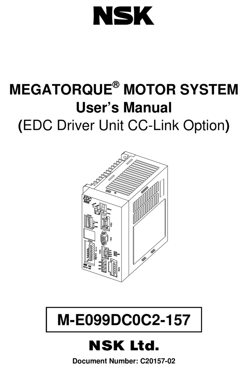
NSK MEGATORQUE MOTOR SYSTEM User manual

Megatorque®Motor System
User’s Manual
(Supplement to the EDC Driver Unit System)
EC-T
Document Number: C20169-03

Limited Warranty
NSK Ltd. warrants its products to be free from defects in material and/or workmanship which NSK
Ltd. is notified of in writing within, which comes first, one (1) year of shipment or 2400 total
operation hours. NSK Ltd., at its option, and with transportation charges prepaid by the claimant,
will repair or replace any product which has been proved to the satisfaction of NSK Ltd. to have a
defect in material and/or workmanship.
This warranty is the sole and exclusive remedy available, and under no circumstances shall NSK
Ltd. be liable for any consequential damages, loss of profits and/or personal injury as a result of
claim arising under this limited warranty. NSK Ltd. makes no other warranty express or implied,
and disclaims any warranties for fitness for a particular purpose or merchantability.
Copyright 2009 by NSK Ltd., Tokyo, Japan
All rights reserved.
No part of this publication may be reproduced in any form
or by any means without permission in writing from NSK
Ltd.
NSK Ltd. reserves the right to make changes to any
products herein to improve reliability, function or design
without prior notice and without any obligation.
NSK Ltd. does not assume any liability arising out of the
Application or use of any product described herein; neither
does it convey any license under its present patent nor the
rights of others.
Patents issued and patents pending.
“MEGATORQUE” is a registered trademark of NSK Ltd. in
Japan and that of NSK Corp. in the United States of America.

— i —
Contents
1. Introduction ------------------------------------------------------------ 1-1
1.1. Precaustions for Use ----------------------------------------------------------------1-1
2. Reference Number and Coding --------------------------------- 2-1
2.1. PN Series Megatorque Motor-------------------------------------------------------2-1
2.2. EDC Driver Unit for PN Series Megatorque Motor ----------------------------2-1
2.3. Cable Set --------------------------------------------------------------------------------2-3
2.4. HandyTerminal -------------------------------------------------------------------------2-3
3. Name of Each Part--------------------------------------------------- 3-1
4. Combination of Motor and Driver Unit--------------------------- 4-1
5. Motor Specifications------------------------------------------------- 5-1
6. Externel Dimensions------------------------------------------------- 6-1
6.1. PN Series Megatorque Motor-------------------------------------------------------6-1
6.2. Driver Unit -------------------------------------------------------------------------------6-2
7. Driver Unit Specifications------------------------------------------- 7-1
8. Installation-------------------------------------------------------------- 8-1
8.1. Environmental Conditions of Motor------------------------------------------------8-1
8.2. Coupling Load to the Motor ---------------------------------------------------------8-1
8.3. Comfirmations of Use Conditios ---------------------------------------------------8-2
Appendix 1: How to Check Motor Condition----------------------A-1

— 1-1 —
1.Introduction
This is the supplementary of the instruction manual “EDC Driver Unit System (Document
Number: C20158).” This supplement describes the Megatorque Motor System composed of the
EDC Driver Unit and the PN series Megatorque Motor. Please refer to the above mentioned
instruction manual (Document No.C20158) for items not described in this document.
1.1. Precautions for Use
!Warning
:
Be sure not to activate the dynamic brake in the following conditions.
Otherwise the dynamic brake circuit may break and the Motor will
enter in a “free run” state, leading to possible injuries.
◊ Do not activate the dynamic brake in normal operations. Stop the Motor by a control
command, not by the dynamic brake. The dynamic brake is an auxiliary function to
stop the Motor immediately in an emergency. In the middle of operation, an alarm, a
warning or the “Emergency stop” input activates the dynamic brake.
• Warnings that initiate “Servo-off” state are “A3” (Software thermal), “C0”
(Position command/Feedback error), “C5” (Field bass error), “F5” (Program
error), and “F8” (Automatic tuning error).
◊ The load inertia to a Motor must be 70 times or less than the Motor inertia (100 times
for the PS1, PS3 and PN2 type Motors). In case of an indexing operation, a position
command shall be 360 degrees or less, while the maximum speed for continual rotation
must be 0.5 sec-1 or less.
(However, there may be a possibility to exceed the above limits in some cases. Please
consult NSK when you require a close investigation on the limits.)
◊ For the PN4180 Motor, be sure to stop the Motor for 20 minutes or longer when you
stop it by the dynamic brake.
!Caution: When the Motor is continually accelerating a high inertial load with high
acceleration, the system constantly outputs a high torque exceeding
the rated torque, and thus likely to activate the warning “A3” (Software
thermal). In such a case take a remedy to decrease the load inertia or
to lower the speed.

— 2-1 —
2. Reference Number and Coding
2. 1. PN Series Megatorque Motor
Fig.2-1: PN Motor
Megatorque Motor
PN Series
M-PN 2 012 K N 201
Motor size code
Notor maximum troque [N・m]
KN: Standard Motor
Design number
2. 2. EDC Driver Unit for PN Series Megatorque Motor
Fig. 2-3: EDC Driver Unit for PN2012 type Motor
EDC Driver Unit
M-EDC
–
PN2012 A B 5 02
–
01
Motor model
Design serial number 02: standard
Power voltage: A: 200 to 230 [VAC] (single phase)
C: 100 to 115 [VAC] (single phase)
Position sensor B: Absolute position sensor Function code: 5: Standard specification
C:CC-Link(Optioanl)
-02: Bundled with connectors, fixing
brackets and an English manual.
-01: Bundled with connectors, fixing
brackets and a Japanese manual.
Default: Not bundled with connectors,
fixing brackets and a manual.
Fig.2-4: EDC Driver Unit for PN3045 types Motor
EDC Driver Unit
M-EDC
–
PN304
5
A B 5 02
–
01
Motor type
Design serial number 02: standard
Power voltage: A: 200 to 230 [VAC] (single phase)
C: 100 to 115 [VAC] (single phase)
Position sensor B: Absolute position sensor Function code: 5: Standard specification
C:CC-Link(Optioanl)
-02: Bundled with connectors, fixing
brackets and an English manual.
-01: Bundled with connectors, fixing
brackets and a Japanese

— 2-2 —
Fig.2-5: EDC Driver Unit for PN4135, and PN4180 types Motor
EDC Driver Unit
M-EDC
–
PN413
5
A B 5 02
–
01
Motor type
Design serial number 02: standard
Power voltage: A: 200 to 230 [VAC] (single phase)
Position sensor B: Absolute position sensor Function code: 5: Standard specification
C:CC-Link(Optioanl)
-02: Bundled with connectors, fixing
brackets and an English manual.
-01: Bundled with connectors, fixing
brackets and a Japanese
2.3. Cable Set
Fig 2-6: Reference number coding of Cable Set
Cable Set for
Megaorque Motor
M-C 004 SCP 03
Example: 002…2m,
004…4m,
008…8m
015…15m
030…30m
Design number
03: Fixed uset ype
13: Flexible type
Cable set for EDC Driver Unit
※The combination with PN2012 becomes it up to 8[m] incable length.
2.4. Handy Terminal
Fig 2-7: Reference number coding of Handy terminal
Handy Terminal M-FHT 21 Handy Terminal serial number

— 3-1 —
3. Name of Each Part
Fig 3-1: PN 2012 type Motor
Mountin
g
surface
Motor connector
Resolver connector
Cover
(Stationary part)
(Rotating part)
Hollow
Rotor
(
Rotatin
g
p
art
)
Fig. 3-2: PN3045, 4135, and 4180 type Motor
Mounting surface
Motor connector
Resolver connector
Cover
(Stationary part)
(Stationary part)
Hollow
Rotor (Rotating part)

— 4-1 —
4. Combination of Motor and Driver Unit
Table4-1: Combination of PN2012 type Motor and Driver Unit
Motor
diameter
[mm]
Motor
reference number
Driver Unit
reference number
¼¼: Code for specification
of bundled items.
Power voltage
[VAC]Cable
reference number Remarks
M-EDC-PN2012AB502-¼¼ 200 to 230
M-EDC-PN2012CB502-¼¼ 100 to 115
• Pulse train
input
M-EDC-PN2012ABC02-¼¼ 200 to 230
ø176 M-PN2012KN201
M-EDC-PN2012CBC02-¼¼ 100 to 115
M-C0¼¼SCP03
(Fixed type cable)
M-C0¼¼SCP13
(Flexible type
cable)
¼¼: Cable length
in meters
01: 1 [m]
02: 2 [m]
03. 3 [m]
04: 4 [m]
05: 5 [m]
06: 6 [m]
07: 7 [m]
08: 8 [m]
• CC-Link
Table4-2: Combination of PN3045, PN4135, PN4180 type Motor and Driver Unit
Motor
diameter
[mm]
Motor
reference number
Driver Unit
reference number
¼¼: Code for specification
of bundled items.
Power voltage
[VAC]Cable
reference number Remarks
M-EDC-PN3045AB502-¼¼ 200 to 230
M-EDC-PN3045CB502-¼¼ 100 to 115
• Pulse train
input
M-EDC-PN3045ABC02-¼¼ 200 to 230
ø210 M-PN3045KN001
M-EDC-PN3045CBC02-¼¼ 100 to 115
• CC-Link
M-EDC-PN4135AB502-¼¼ • Pulse train
input
M-PN4135KN001
M-EDC-PN4135ABC02-¼¼ • CC-Link
M-EDC-PN4180AB502-¼¼ • Pulse train
input
ø280
M-PN4180KN001
M-EDC-PN4180ABC02-¼¼
200 to 230
M-C0¼¼SCP03
(Fixed type cable)
M-C0¼¼SCP13
(Flexible type
cable)
¼¼: Cable length
in meters
01: 1 [m]
02: 2 [m]
03. 3 [m]
04: 4 [m]
05: 5 [m]
06: 6 [m]
07: 7 [m]
08: 8 [m]
09: 9 [m]
10: 10 [m]
15: 15 [m]
20: 20 [m]
30: 30 [m] • CC-Link

— 5-1 —
5. Motor Specifications
Table 5-1: PN series Megatorque Motor
Reference number
Item [Unit] M-PN2012KN201
M-PN3045KN001
M-PN4135KN001 M-PN4180KN001
Motor outside diameter [mm] ø176 ø210 ø280
Maximum output torque [N•m] 12 45 135 180
Rated output torque [N•m] 2 15 45 60
Motor height [mm] 35 85 95 112
Motor hollow diameter [mm] 36 56 50 50
Maximum velocity [s-1] 2 3
Rated velocity [s-1] 1 1
Resolution of position
sensor [Count/rev.] 2 621 440
Absolute position
accuracy [arcsec.] 90 *1,*3
Repeatability [arcsec.] ±2
Allowable axial load [N] 1 000 4500 9500
Allowable radial load [N] 20 *280 160 200
Rotor inertia [kg•m2] 0.0024 0.011 0.057 0.065
Recommended
moment load [kg•m2] 0.02 to 0.24 0.11 to 0.77 0.57 to 3.99 0.65 to 4.55
Mass [kg] 3.7 13 26 31
International protection code IP30 equivalent
Environmental conditions Ambient temperature: 0 to 40[°C] Humidity: 20 to 80 [%],
In door use only. Free from condensation, dust and corrosive gas.
• SI Unit System: 1N = 0.102 kgf. 1N•m = 0.102 kgf•m
*1. This accuracy is guaranteed at the temperature of 25 ±5 [°C].
*2. The use condition must clear the recommended moment load and the maximum radial load of 300[ N].
*3.The cable length of PN2012 becomes it up to 8[m] .
!Caution : Axial load Fa and Moment load M shall be less than the limits specified
in the above table.
Fig. 5-1: Loads applied to a Motor
Table 5-2
:
Dimension A (distance between the bearing and the rotor)
Motor reference
number M-PN2012KN201 M-PN3045KN001 M-PN4135KN001 M-PN4180KN001
A [mm] 16.7 33.8 54.2 54.2
1) When F is an external force
• Axial load: Fa=F+F0
• Moment load: M=0
3) When F is an external vertical load
• Radial force: Fr=F+F0
• Moment load: M=F×(L+A)+F0×(l+A)
2) When F is an external force
• Axial load: Fa=F+F0
• Moment load: M=F×L
F
F0
F
F0
L
F
F0
L
A
l

— 6-1 —
6. External Dimensions
6.1. PN Series Megatorque Motors
!Caution: Bending radius of the outgoing lines of Motor cable (ø7) and resolver
cable (ø7) shall be R30 [mm] or less.
!Caution: Do not use outgoing lines of Motor cable and Resolver cable as a part of
the flexible cable.
!Caution: Do not apply any stress (tension or vibration) to the connecting position
of the outgoing lines and a connector. If not, it may result in a
disconnection or a loose connection.
Fig. 6-1: PN2012 type Motor
Fig. 6-2: PN3045tyoe Motor

— 6-2 —
Fig 6-3: PN4135 type Motor
Fig 6-4: PN4180 type Motor

— 6-3 —
6.2. Driver Unit
Fig.6-5
:
EDC Driver Unit for PN2012 type Motor
Fig. 6-6: CC-Link Compatible EDC Driver Unit for PN2012 type Motor

— 6-4 —
Fig. 6-7 EDC Driver Unit for PN3045, PN4135 and PN4180 Megatorque Motors
Fig. 6-8 CC-Link Compatible EDC Driver Unit for PN3045, PN4135 and PN4180 Megatorque Motors

— 7-1 —
7. Driver Unit Specifications
Table 7-1: EDC Driver Unit
Item PN2012 PN3045 PN4135 PN4180
Rated output [Arms]1.2 4.5 4.5 4.5
Output
current Maximum output [Arms]6.5 14.9 14.9 14.9
Rated capacity [kVA]0.1 0.5 0.9 1.1
Max. capacity [kVA]2.1 4.4 5.0 5.1
Control power source
Power
input Main power source
Single phase 100 to 115 [VAC]
Single phase 200 to 230 [VAC]
Fluctuation of voltage:±10[%] or less
Single phase 200 to 230 [VAC]
Fluctuation of power voltage: ±10[%]
Position sensor resolution [count/rev] 2 621 440
Maximum velocity [s-1]2 3
Positioning operation mode Program operation (256 channels), Pulse train input, RS-232C serial communication command, Jog, Home Return
Pulse train command Photo coupler input: Maximum pulse frequency: 1 [MHz]
Input format: CW/CCW, Pulse and direction, ΦA/ΦB
Electronic gear A/B multiple available (1 000 to 5 242 880 [count/rev])
Input
signal Control input
Photo coupler input (±Common available), 17 input ports, 24 [V] input voltage
Emergency stop, Alarm clear, Over travel limit +/-, Servo ON, Program operation start, Stop,
Internal program 内channel switching (0 to 7), Jog, Jog direction,
(Hold, Velocity override, Integration OFF, Home return start and Home position limit)*1
Position feedback signal
Signal format: ΦA/ΦB/ΦZ line drive, Free resolution setting to ΦA/ΦB available.
Resolution of ΦA/ΦB: • Shipping set: 20 480 [count/rev.] (Quadrupled: 81 920 [count/rev])
• Maximum 1 310 720 [count/rev] (Quadrupled: 5 242 880 [Count/rev])
* The maximum signal frequency is limited to 781 [kHz] and thus the setting of resolution limits the maximum
revolution speed. (Maximum speed: [s-1] = 781 [kHz]/Resolution of ΦA [or ΦB]
Resolution of ΦZ: 80 [count/rev]
Output
signal
Control output
Photo coupler output (±Common available), 7 output ports. Maximum switching capacity: 24 [VDC]/50 [mA]
Driver unit ready, Warning, Over travel limit detection +/- direction, Servo state, Busy, In-position, Target
proximity A
(Target proximity B, Zone A•B•C, Travel limit +/-, Normal, Position error under/over, Velocity error
under/over, Torque command under/over, Thermal loading under/over, Home return complete, Home position
defined)*1
Alarm
Excess error, Program error, Automatic tuning error, Position command/Feedback error, Field bus warning,
Software thermal error, Home position undefined, Main AC line under voltage, Travel limit over, RAM error,
ROM error, System error, Interface error, ADC error, Emergency stop, CPU error, Fieldbus error, Position
sensor error, Absolute position error, Motor cable disconnected, Excess velocity, Resolver excitation amplifier
alarm, Commutation error, Overheat, Main AC line over voltage, Excess current, Control AC line under voltage,
Power module error
Monitors Analog monitor ×2 (Free range and offset setting), RS-232C monitor
Communication RS-232C serial communication (Asynchronous, 9 600 [bps])
Data backup EEPROM (Overwriting and deleting of parameters are limited to 100 000 times.)
Others • Automatic tuning • Function setting to Input/Output port
• Temporal parameter setting by a program operation. • Individual setting of acceleration and deceleration
• Acceleration profiling (Modified sine, Modified trapezoid, Cycloid and Half sine)
Fieldbus CC-Link Ver.1.10 compatible (Optional EDC Driver Unit compatible to CC-Link is required.)
• Ambient temperature
• Storage temperature • Ambient temperature: 0 to 50[℃] • Storage temperature -20 to 70[℃]
Ambient/storage
humidity 90[%] or less (No condensation)
Environ-
ment
Vibration resistance 4.9 [m/s2]
Regeneration Optional dump resistor available when the regeneration current is beyond the capacity of built-in resistor.
(M-E014DCKR1-100, M-E014DCKR1-101) • Connect to R+,R-,SE+ and SE-. (Never short-circuit them.)
Built-in
function Dynamic brake Functions at the state of Power-off, Servo-off and Warning. The command KB terminates the dynamic brake
function. (Refer to “9.2. Glossary of Command and parameter.)
UL UL508C
LVD EN50178
Compatible
safety
regulation CE Marking EMC EMI:EN55011EMS:EN61000-6-2
RS-232C CN1
D-sub 9 pins
Control I/O CN2 Standard: half pitch connector 50 pins
CC-Link compatible: Half pitch 10 pins
Position
sensor CN3 Half pitch connector 14 pins
Motor/Optional
dump resistor CN4 Plastic connector (UL and CE qualified)
Control/Main
power CN5 Plastic connector (UL and CE qualified)
Connectors
CC-Link CN6
Plastic connector 5 pins
Mass [kg] Standard: 1.1
CC-Link compatible: 1.3
Standard: 1.8
CC-Link compatible: 2.0
*1: These functions become effective by changing some functional allocation of control Input/Output.

— 8-1 —
8. Installation
8.1. Environmental Conditions of Motor
Use the Motor in the indoor conditions free from dust and corrosive gas.
The operating ambient temperature of the Motor shall be 0 to 40°C.
The PN type Megatorque Motors are neither dust-proof nor waterproof.
Do not expose the Motor to water or oil from any source.
It is essential to securely fix the Motor to a mounting base of which rigidity is sufficient enough. .
Otherwise, mechanical resonance may occur.
!Warning
:
When fixing the Motor, use bolt holes on its bottom.
The flatness of the mounting surface for the Motor shall be 0.02 mm or less.
The Motor can be mounted vertically or horizontally.
!Caution: Do not connect the outgoing lines of the Motor cable and resolver
cable of the PN2012 type Motor to a moving part. The bending radius
of the outgoing lines shall be 30 mm or less.
8.2. Coupling a Load to the Motor
!Warning
:
Fix the load using the bolt holes on the rotor surface. Be sure to fasten
the bolts firmly.
The table bellow shows the tightening torque of bolt and thread depth for each
Motor type.
Motor type PN2012 PN3045 PN4135 PN4180
Tightening torque [N・m] 5.3 to 6.5 7.8 or less 20 or less 20 or less
Thread depth [mm] 5 to 6.5 6 to 7.5 10 to 11.5 10 to 11.5
!Caution: When using the pinhole on the rotor, please follow the notes below.
Set the tolerance of pin diameter to a lose fit.
Do not apply excessive load or shock to the Motor when inserting the pin to the
pinhole.
The pinhole is simply for positioning of a load to the Motor. Do not use the
pinhole to support the load.

— 8-2 —
8.3. Confirmation of Use Conditions
In case of the Megatorque Motor system, the moment of inertia of load is extremely higher than
that of the rotor. The table bellow shows the allowable moment of inertia for each Motor type.
Table 8-1
:
Allowable moment of inertia for Motor
Motor type Moment of inertia of the rotor
[kg・m2] Allowable moment of inertia
[kg・m2]
PN2012 0.0024 0.24
PN3045 0.011 0.77
PN4135 0.057 3.99
PN4180 0.065 4.55
!Caution: Be sure to confirm the allowable moment load and axial load to the
Motor under the use conditions.
Please refer to “5. Motor Specifications” for the allowable moment load and
axial load for each Motor.

— A-1 —
Appendix 1: How to Check Motor Condition
Examine the resistance and the insulation resistance of the Motor winding to check if the Motor is in
normal condition. It can be regarded as it is normal if all check results are within the specifications.
First, check the winding resistance including the Motor cable. If the result is not satisfactory, check the
Motor only.
1. Resistance check of Motor winding
Fig A-1: Check with the cable set
Fig A-2: Check with the Motor only
Do not turn the rotor while checking the Motor winding.
Table A-1: Checking points
Cable connector Motor connector Result
Phase UV (1) ↔(2)
(U) (V) (1) ↔(2)
(U) (V)
Phase VW (2) ↔(3)
(V) (W) (2) ↔(3)
(V) (W)
Phase WU (3) ↔(1)
(W) (U) (3) ↔(1)
(W) (U)
Table A-2: Resistance specification of Motor winding
Motor type Winding resistance [Ω] Specification
PN2012 15.2
PN3045 1.9
PN4136 2.6
PN4180 3.2
1. ± 30%of the value in the left
2. Variation between each phase UV, VW, and WU
is less than 15%
Please ask NSK for a Motor with special winding specifications or a Cable longer than 4 m.
PN3 or PN4
PN2
(
1
)
(2)
(3)
(4)
(5)
(
6
)
(7)
(8)
(9)
Tester
PN3 or PN4
PN2
(1)
(
3
)
(4)
(2)
Tester

— A-2 —
2. Resistance check of the resolver winding
Fig A-3: Check with the Cable set
Fig A-4: Check with the Motor only
Table A-3: Checking points of the resolver with an absolute position sensor and winding resistance
Cable connector Motor connector Result Specification
INC-A (1) ↔(9)
(INC-A) (INC・COM) A(1) ↔A(4)
(INC-A) (INC・COM)
INC-B (2) ↔(9)
(INC-B) (INC・COM) A(2) ↔A(4)
(INC-B) (INC・COM)
INC-C (3) ↔(9)
(INC-C) (INC・COM) A(3) ↔A(4)
(INC-C) (INC・COM)
1.Resistance
• PN2012: 7.7 ±1 Ω
•PN3 and PN4: 9.8 ±1 Ω
2. Variation between each phase A,
B and C shall be 1.0 Ωor less.
ABS-A (5) ↔(8)
(ABS-A) (ABS・COM) B(1) ↔B(4)
(ABS-A) (ABS・COM)
ABS-B (6) ↔(8)
(ABS-B) (ABS・COM) B(2) ↔B(4)
(ABS-B) (ABS・COM)
ABS-C (7) ↔(8)
(ABS-C) (ABS・COM) B(3) ↔B(4)
(ABS-C) (ABS・COM)
1.Resistance
• PS1 type: 8.3 ±1 Ω
• PS3 type: 9.8 ±1 Ω
2. Variation between each phase A,
B and C shall be 1.0 Ωor less.
* Please ask NSK for the specifications of the Motor with special winding, and the Cable longer than 4 [m].
Fig A-5: Connection of the Motor with the absolute position sensor [Reference only]
PN3 or PN4
PN2
(1)
(2)
(
3
)
(4)
(
5
)
(6)
(7)
(8)
(9)
(10)
(
11
)
(12)
(13)
(14)
Tester
A
(1)
A
(2)
A
(3)
A
(4)
A
(5)
B(1)
B
(
2
)
B(3)
B(4)
B(5)
PN
3orPN4
PN2
Tester
Absolute resolver
Driver unit connector Motor connecter
INC-A
INC-B
INC-C
INC-common
ABS-A
ABS-B
ABS-C
ABS-common
FG (shielded wire)
common
ΦC
ΦB
ΦA
Incremental
resolve
r
ΦA
ΦB
ΦC
common
(1)
(2)
(3)
(5)
(6)
(7)
(8)
(9)
(14)
A(1)
A(2)
A(3)
B(1)
B(2)
B(3)
B(4)
A(4)

— A-3 —
3. Insulation resistance check of Motor winding
!Caution: Disconnect the Motor from the Driver Unit when checking insulation
resistance of the Motor.
!Caution: Checking voltage must be 500[ VDC] or less.
Fig A-6: Check with the Cable
Fig A-7: Check the Motor only
Table A-4: Checking point
Cable connector Motor connector Result
øU – PE (1) ↔ (9)
(U) (PE) (1) ↔ (4)
(U) (PE)
øV – PE (2) ↔(9)
(V) (PE) (2) ↔(4)
(V) (PE)
øW – PE (3) ↔ (9)
(W) (PE) (3) ↔(4)
(W) (PE)
Table A-5: Specification of insulation resistance (Common to all type of Motor)
Specification
With cable 1 [MΩ] or over
Motor only 2 [MΩ] or over
4. Visual check of the Motor and the Cables
Check the Motor for any damage.
Check the cable for any damage on the cable insulation.
PN3 or PN4
PN2
(1)
(2)
(3)
(4)
(5)
(6)
(7)
(8)
(9)
Tester
PN3 or PN4
PN2
(1)
(3)
(4)
(2)
Tester

— A-4 —
(Blank Page)
Other manuals for MEGATORQUE MOTOR SYSTEM
1
Table of contents
Other NSK Engine manuals
Popular Engine manuals by other brands
Crestron
Crestron QMT 5 Series installation guide
Tomahawk
Tomahawk BLACK BLOCK 125-TGW instruction manual
Festo
Festo EMMT-AS Series operating instructions
Briggs & Stratton
Briggs & Stratton Vanguard 50000 Operator's manual

TJERNLUND
TJERNLUND HS-3 manual
ABB
ABB Baldor-Reliancer EC Titanium quick start guide

