NSK NS Series Instruction Manual

2
NSK linear guides are high quality and are
easy to use. NSK places importance on safety
in design. For maximum safety, please follow
precautions as outlined below.
(1) Lubrication
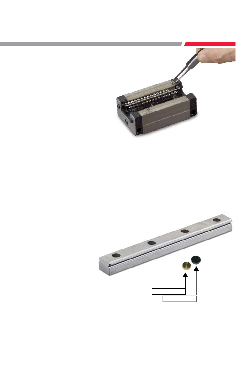
a. Remove the rust preventative rail-coating
before installation. If you are using oil as
a lubricant, consult NSK for compatibility
issues with the pre-packed factory grease.
(2) Handling
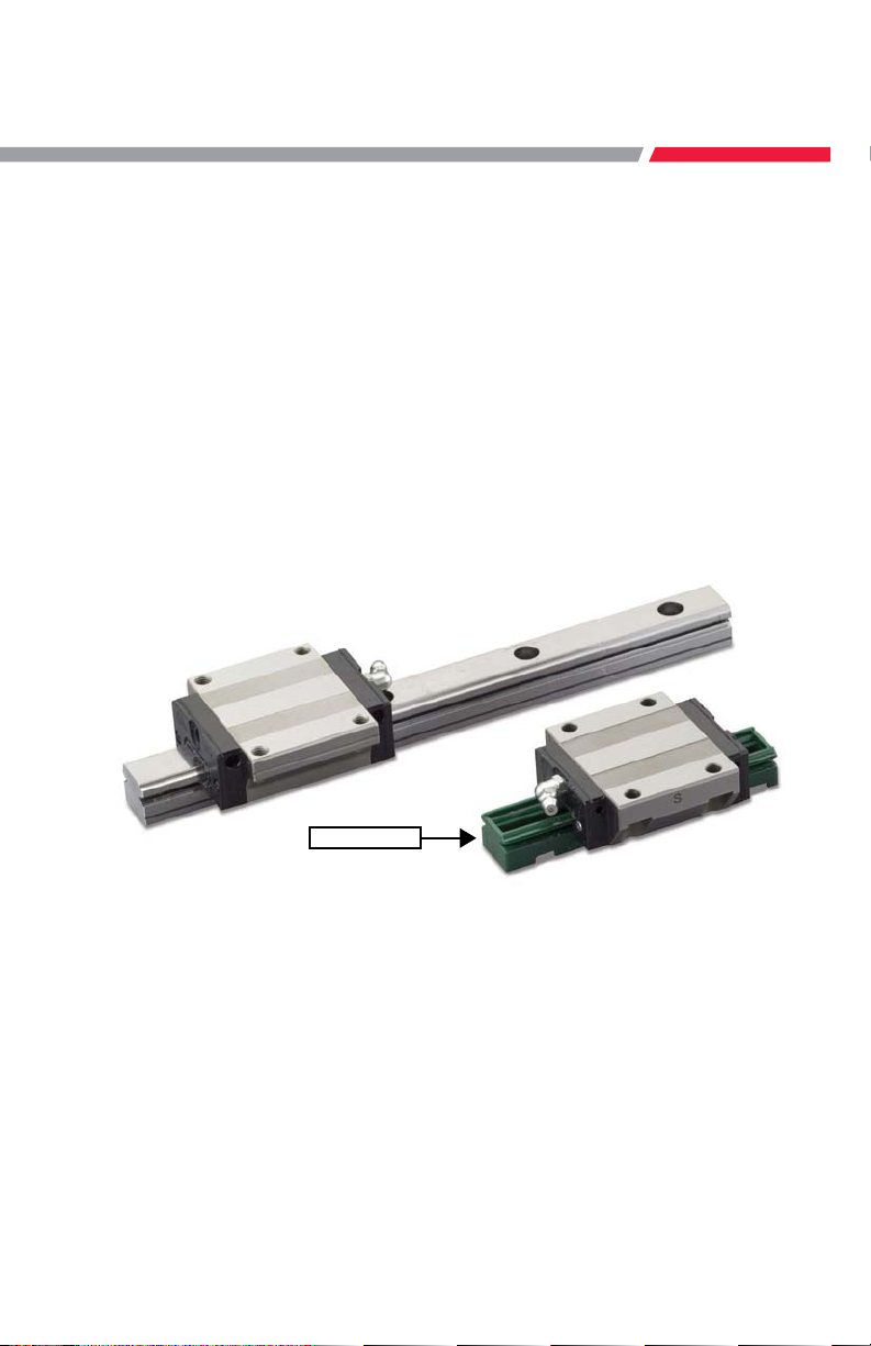
a. Interchangeable ball slides (randomly
matching types between rail and ball
slide) are installed to the provisional rail
when they leave the factory. Handle the
ball slide with care during installation to
the rail.
b. Do not disassemble the guide unless
absolutely necessary.
c. Ball slide will move easily. Make sure that
the ball slide does not disengage from the
rail.
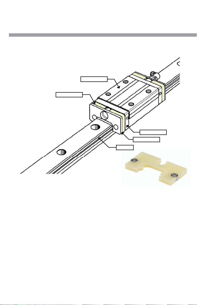
d. Standard end cap is made of plastic and
may break if a direct force is applied.
(3) Precautions in use
a. Make every effort not to allow dust and
foreign objects to enter.
b. The temperature of the place where
linear guides are used should not exceed
80˚C (excluding heat-resistant type linear
guides.) A higher temperature may
damage the plastic end cap.
c. If the user cuts the rail, thoroughly
remove burrs and sharp edges on the cut
surface.
d. When hanging upside-down (e.g. the rail
is installed upside-down on the ceiling
in which the ball slide faces downward),
should the end cap be damaged, causing
the balls to fall out, the ball slide may be
detached from the rail and fall. For such
use, take measures including installing a
safety device.
(4) Storage
a. Linear rail may bend if stored
inappropriately. Place it on a suitable
surface, and store it in a flat position.
Confirm lubrication.
Handle with care.
Do not drop.
Do not disassemble.
Do not contaminate.
Do not hang upside down.
Temperature limitation.
Store in the correct position.
Do not use direct force.
Linear Guide: Handling Precautions

3
Thank you for choosing NSK linear guides. This manual briefly describes the recommended
handling and installation of NSK linear guides for general industrial use.
There are two methods of installing linear guides. The first uses a datum shoulder on
the mounting base and provides accurate horizontal alignment in the same way used for
machine tools. The other method uses the first rail as a reference for the second rail and is
generally used when smooth motion versus high accuracy is required.
NSK recommends the interchangeable series NH and NS linear guides for general industrial
applications. Their self-aligning feature means a greater tolerance for alignment errors and
less time spent on installation. Also, they are interchangeable between rail and slider, easily
allowing the addition or replacement of parts.
For interchangeable NH and NS Series linear guides, the ball slides and the rails are stocked
separately. The ball slides are mounted on plastic provisional rails that allows for easy
transfer of the ball slide to and from the steel rail.
Provisional rail.
Installation Procedures

4
The following is a description of how the ball slide should be removed from and replaced on
the linear guide rail.
The ball slide is held on the provisional rail using a rubber band. The rubber band should
catch the bottom channel in the provisional rail and then twist around to secure the ball slide.
Linear guide rail
Provisional rail
When transferring the ball slide from the provisional rail onto the rail, or vice versa, butt the
provisional rail up against the rail and slide the ball slide directly from one onto the other.
It is a good idea to secure the ball slide onto the provisional rail with a rubber band after
removal from the rail.
The ball slides are designed with
retaining wires to prevent the balls
from falling out when they are
removed from the rail. However,
NSK recommends that the ball slides
should be stored on a provisional
rail prior to installation to prevent
contamination from dust and other
foreign objects.

5
If a ball is accidentally dropped from
the ball slide, it should be cleaned and
replaced to the appropriate groove. The
correct groove can be determined by
the size of the clearance between the
balls (the groove missing the ball will
have greater clearance than the other
grooves). It is normal to have a gap of
1.5 ball diameters in each groove.
The following section describes how to install the linear guides on the machine.
Ball slides and rails are supplied separately. Each is wrapped in vinyl sheet, and packed in a
container.
Plastic and brass rail caps are an
available option for use in
high contamination areas to
prevent debris build-up in the
bolt holes which may damage
the slider. Please request these
at time of order.
Brass cap
Plastic cap

6
The rail is always shipped with rust preventive oil, which should be wiped off before use. NH
and NS Series ball slides are pre-packed with grease, so no cleaning is required prior
to installation.
Now the linear guide is ready for installation. Place it carefully on the mounting surface.
Then tighten the bolts with a torque wrench
to the specified torque starting from one
end.
In NSK linear guides, the mounting bolt holes are processed after heat treatment using
a precision machining center; therefore, the bolt hole pitch accuracy is as good as the
positioning accuracy of the machine, which is considered very good.
When tightening the bolts, be sure to start at one end and work in order to the other end. If
the bolts are tightened at the middle first, it tends to leave the rail curved. If you suspect this
has happened, loosen the bolts and start again.
For Smooth Motion of General Machinery
Snugly tighten the mounting bolts temporarily
so that the rail is firmly against the bed.

7
The rail that has been tightened can now be used as a reference rail. Using a vernier calipers
or other accurate tool, measure the distance between the two rails, and adjust each end until
they are the same. Tighten a bolt snugly at each end of the rail.
The next step is to install the table,
and to use the table to align the
rails.
Firmly bolt the table to ball slides 1 and
2 on the firmly secured rail as shown in
the diagram. Then position ball slide 3 at
the left end of the adjusting rail, and bolt
the table to this ball slide. Move the ball
slide 3 to right and bolt the table to the ball
slide 4.
Move the table to one end of the rails,
and start tightening the adjusting rail
bolt sequentially to the specified torque
while checking excessive friction of table
movement. Continue moving the table
down the rail tightening each adjacent
bolt until they have all been tightened.
This method of assembly is for general industrial machinery where smooth linear motion is the
overall objective. When precision accuracy is required, read on to the following procedure.

8
For Greater Accuracy of General Machinery
When bolting the first rail on the machine
base, align it straight using a straightedge
and a dial indicator.
Bolt on the rail at the both ends lightly, and
position a straightedge beside it. Set the
straightedge parallel to the rail measuring
distance A1 and A2 by a vernier calipers or
some other accurate measuring tool.
Move the dial indicator along the straightedge, and take readings at every bolt hole along the
rail. Make fine adjustment of the rail to the straightedge until the desired reading is made,
and tighten the bolt to the specified torque.
When all of the bolts have been tightened, slide the dial indicator from one end of the rail to
the other to ensure that the desired straightness has been achieved.
During installation, it is recommended that accuracy is checked to ensure smooth operation.
Position the dial indicator on two ball slides
on the reference rail as shown in the diagram.
Tighten bolts of the adjusting side rail
sequentially from the one end while noting
the reading of the dial indicator.
Straightness of NSK linear guides is controlled
so that it can be easily adjusted manually for
easy installation.

9
This section describes the allowable tolerances for installation in order to maximize the
performance of NSK linear guides.
We recommend that the mounting errors e1or e2do not exceed the values shown in the table
below. Consult “Precision Machine Components” catalog for linear guides series not shown.
If the error readings are equal to or less than the above values, you have correctly assembled
the parts. For maximum accuracy, keep the readings below what is shown in the table.
If your readings are greater than these values, it is necessary to remove the parts and
start over. Please contact your local NSK office with any questions or for assistance. Visit
www.nskamericas.com for contact information.
Recommended allowable installation error of the NS Series (Maximum)
Item
Model No. 15 20 25 30 35
Clearance
Z0, ZT
Permissible values of parallelism
in two rails: e1
20 22 30 35 40
Permissible values of parallelism
(height) in two rails: e2
375mm/500mm
Preload
Z1, ZZ
Permissible values of parallelism
in two rails: e1
15 17 20 25 30
Permissible values of parallelism
(height) in two rails: e2
330mm/500mm
Recommended allowable installation error of the NH Series (Maximum)
Item
Model No. 20 25 30 35 45 55 65
Clearance
Z0, ZT
Permissible values of parallelism
in two rails: e1
30 40 45 55 65 80 110
Permissible values of parallelism
(height) in two rails: e2
375mm/500mm
Preload
Z1, ZZ
Permissible values of parallelism
in two rails: e1
20 25 30 35 45 55 70
Permissible values of parallelism
(height) in two rails: e2
330mm/500mm

10
To maintain the NSK K1TM Seal’s high efficiency over a long period of time, please
follow these instructions.
K1TM Handling Instructions
1. Max. operating temperature: 50°C (122°F)
Max. peak temperature: 80°C (176°F)
If not installed immediately, they should be kept refrigerated.
Avoid storage in direct sunlight.
2. Never leave the linear guide in close proximity to grease-removing organic
solvents such as hexane, thinners, etc. Never immerse the linear guide in
kerosene or rust preventative oils which contain kerosene.
Note
Other oils such as: water-based cutting oil, oil-based cutting oil, grease (mineral oil-AS2, ester-PS2)
present no problems to the K1TM lubricating units performance.
NSK K1
TM
Rail
Ball Slide
End (rubber) Seal
End (rubber) Seal

11
K1TM Assembly Instructions
1. Slide linear bearing on to the linear rail, using the plastic provisional rail supplied.
2. Remove the grease fitting from the end of the bearing.
3. Remove the Phillips screws (2 pieces).
4. Remove the end seal from end of bearing.
5. Install threaded plug from K1TM kit (or see option 9 and 10 depending on
application).
6. Install the cover plate from the K1TM kit, to the end of bearing, against the end
cap.
7. Install K1TM lubricating unit without fixing rings, so it can be expanded over the
rail.
8. Put the three (3) fixing rings in position on the K1TM lubricating unit.
9. Replace the end seal, in front of the K1TM lubricating unit.
10. Install connector screw for grease fitting.
11. Replace the grease fitting in connector screw.
12. Install the extension Phillips screws (2 pieces, supplied with the K1TM seal kit).
Note
The K1TM lubricating unit has a shelf life. They should be installed immediately upon receipt. It is important
to avoid direct sunlight and extreme heat conditions.

Please also visit our website: www.nskeurope.com
Global NSK: www.nsk.com
UK
NSK UK Ltd.
Northern Road, Newark
Nottinghamshire NG24 2JF
Tel. +44 (0) 1636 605123
Fax +44 (0) 1636 643276
France & Benelux
NSK France S.A.S.
Quartier de l’Europe
2, rue Georges Guynemer
78283 Guyancourt Cedex
Tel. +33 (0) 1 30573939
Fax +33 (0) 1 30570001
Germany, Austria,
Switzerland, Nordic
NSK Deutschland GmbH
Harkortstraße 15
40880 Ratingen
Tel. +49 (0) 2102 4810
Fax +49 (0) 2102 4812290
info-de@nsk.com
Italy
NSK Italia S.p.A.
Via Garibaldi, 215
20024 Garbagnate
Milanese (MI)
Tel. +39 02 995 191
Fax +39 02 990 25 778
Middle East
NSK Bearings Gulf Trading Co.
JAFZA View 19, Floor 24 Office 2/3
Jebel Ali Downtown,
PO Box 262163
Dubai, UAE
Tel. +971 (0) 4 804 8205
Fax +971 (0) 4 884 7227
Poland & CEE
NSK Polska Sp. z o.o.
Warsaw Branch
Ul. Migdałowa 4/73
02-796 Warszawa
Tel. +48 22 645 15 25
Fax +48 22 645 15 29
Russia
NSK Polska Sp. z o.o.
Russian Branch
Office I 703, Bldg 29,
18th Line of Vasilievskiy Ostrov,
Saint-Petersburg, 199178
Tel. +7 812 3325071
Fax +7 812 3325072
South Africa
NSK South Africa (Pty) Ltd.
25 Galaxy Avenue
Linbro Business Park
Sandton 2146
Tel. +27 (011) 458 3600
Fax +27 (011) 458 3608
nsk-sa@nsk.com
Spain
NSK Spain, S.A.
C/ Tarragona, 161 Cuerpo Bajo
2aPlanta, 08014 Barcelona
Tel. +34 93 2892763
Fax +34 93 4335776
info-es@nsk.com
Turkey
NSK Rulmanları Orta Doğu Tic. Ltd. Şti
19 Mayıs Mah. Atatürk Cad.
Ulya Engin İş Merkezi No: 68/3 Kat. 6
P.K.: 34736 - Kozyatağı - İstanbul
Tel. +90 216 4777111
Fax +90 216 4777174
: LG_HANDBOOK - REV 2 / APB / 1M15 ( NSK Americas )
Every care has been taken to ensure the information in this publication is accurate but no liability can be accepted for
any errors or omissions. © Copyright NSK 2017. The contents of this publication are the copyright of the publishers.
Ref
NSK Sales Offices – Europe, Middle East and Africa
This manual suits for next models
13
Table of contents
Other NSK Industrial Equipment manuals