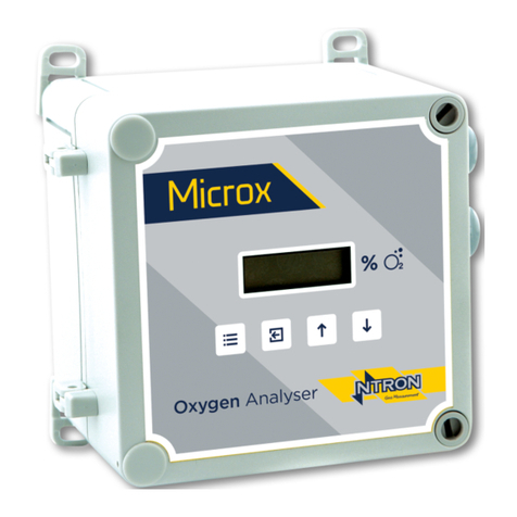
Ntron OxyTX Specification sheet

OxyTx Oxygen
Analyser/Transmitter
With Remote Sensor
Part No. 01-507
Operation and Installation Manual
Rev.1.3
10/2013

Ntron OxyTX
Operation and Installation Manual
Revised:10/2013 ECN00008
Part No.:01-507
Ntron Ltd, Mullaghboy Industrial Park, Navan, Co Meath, IRELAND
Tel: + 353 (46)9071333 • Fax: + 353 (46)9071331 •
Ntron Ltd, Dallam Court, Dallam Lane, Warrington WA2 7LT, UNIITED KINGDOM
Tel: + 44 (161) 930 8690 • Fax: + 44 (161) 930 8691
TABLE OF CONTENTS
1. DESCRIPTION ........................................................................................... 03
2. APPLICATION ........................................................................................... 04
3. INSTALLATION ......................................................................................... 05
4. OPERATION.............................................................................................. 08
5. MAINTENANCE......................................................................................... 15
6. TECHNICAL SPECIFICATIONS.................................................................... 16
7. TROUBLESHOOTING ................................................................................. 17
8. SPARE PARTS LISTING.............................................................................. 18
PAGE 2OF 19

Ntron OxyTX
Operation and Installation Manual
Revised:10/2013 ECN00008
Part No.:01-507
Ntron Ltd, Mullaghboy Industrial Park, Navan, Co Meath, IRELAND
Tel: + 353 (46)9071333 • Fax: + 353 (46)9071331 •
Ntron Ltd, Dallam Court, Dallam Lane, Warrington WA2 7LT, UNIITED KINGDOM
Tel: + 44 (161) 930 8690 • Fax: + 44 (161) 930 8691
DESCRIPTION
Ntron’s OxyTx is a digital 0 - 25% Oxygen Transmitter. It offers the following
features:
•Digital display 0 - 25% oxygen
•Compact size
•Non intrusive calibration
•ATEX / Cenelec Certified Device which can be mounted in Haz. areas.
•Analog 4 - 20 mA Output (Loop Powered)
ATEX Marking:
II 2 G Ex ia IIC T4 Gb (-20°≤TA≤+60°C)
Ui=30V, Ii= 0.15A, Pi= 0.81W, Ci= 10nf, Li= 0
Easy to Install:
The wall mounted OxyTx Transmitter is compact for easy mounting. the oxygen
sensor is provided loose, for mounting at an appropriate point in the sample stream up
to 300 metres away (3 metre cable supplied as standard).
The OxyTx is a loop powered Oxygen Transmitter designed to monitor Oxygen
concentrations within any gas mixture. The transmitter has a loop powered 4 - 20 mA
output for the range 0 - 25% Oxygen.
The large 4 digit LCD display provides local indication of Oxygen concentration and
there is also a green flashing LED to indicate power ‘on’.
Sensor OxyTx Isolation Barrier
By Customer
Hazardous
Area
Connection
Cable
Safe Area
Supplied by Ntron
PAGE 3OF 19

Ntron OxyTX
Operation and Installation Manual
Revised:10/2013 ECN00008
Part No.:01-507
Ntron Ltd, Mullaghboy Industrial Park, Navan, Co Meath, IRELAND
Tel: + 353 (46)9071333 • Fax: + 353 (46)9071331 •
Ntron Ltd, Dallam Court, Dallam Lane, Warrington WA2 7LT, UNIITED KINGDOM
Tel: + 44 (161) 930 8690 • Fax: + 44 (161) 930 8691
APPLICATION
The Ntron Series OxyTx when used with the Ntron “OC” series Oxygen Sensors
measures the current output of the Oxygen sensor, which the microprocessor-based
electronics converts to Oxygen concentrations. The Ntron Oxygen Sensor measures
Oxygen volume directly. It is unaffected by barometric changes. This is unlike most
Oxygen analysers that measure the partial pressure of Oxygen and convert that
measurement to percentage volume. Designed for harsh Industrial environments, the
rugged screw-on Ntron Oxygen Sensor is simple to replace and disposable. The
OxyTx is industrial and rugged and housed in an ABS IP66 enclosure. The large 4
digit LCD display provides local indication of Oxygen concentration. Calibration is
“non invasive” by push button operation eliminating the need to adjust
potentiometers. A tamper-proof cover is opened to reveal push buttons offering the
functions of configuration and calibration without the need to open the enclosure.
This important feature permits operations and maintenance within rated areas.
PAGE 4OF 19

Ntron OxyTX
Operation and Installation Manual
Revised:10/2013 ECN00008
Part No.:01-507
Ntron Ltd, Mullaghboy Industrial Park, Navan, Co Meath, IRELAND
Tel: + 353 (46)9071333 • Fax: + 353 (46)9071331 •
Ntron Ltd, Dallam Court, Dallam Lane, Warrington WA2 7LT, UNIITED KINGDOM
Tel: + 44 (161) 930 8690 • Fax: + 44 (161) 930 8691
INSTALLATION
Mounting:
The OxyTx Analyser is designed for wall mounting:
•Area classification (details marked on ID plate of unit as below).
•Dimensions: 122 mm x 122 mm x 75 mm
•Enclosure environmental rating to IP66.
Care should be taken when mounting the Oxygen Analyser to:
•Protect from vibration, contact with liquids in any form.
•Keep away from temperature extremes.
•Protect from sources of Electromagnetic Radiation, High Voltage and Large
Electric Motors
Sensor Mounting:
The sensor can be mounted via a screw on stainless steel base and should be located
no more than 300 meters from the analyser (3 meter cable supplied as standard).
Two types of sensor bases are available with different types of process connection.
They are the Flow-Through base and the 2” Tri-Clamp base. The flow-through base
is to be mounted in the sample flow via the 1/8” NPT fitting holes drilled and tapped
into the sides of the base. Provisions should be made to provide a suitable calibration
gas or air to the sensor for periodic calibration. The sample flow must be regulated to
no more than 4 PSIG with a minimum flow of 100ml/min. The sensor base is
provided with mounting holes. It should be mounted to a suitable solid surface to
allow easy access for sensor maintenance. The 2” Tri-Clamp base can be coupled to a
mating connection of similar size. The minimum flow conditions above will not
apply, however the sensor should not be exposed to pressure conditions above 4
PSIG.
PAGE 5OF 19

Ntron OxyTX
Operation and Installation Manual
Revised:10/2013 ECN00008
Part No.:01-507
Ntron Ltd, Mullaghboy Industrial Park, Navan, Co Meath, IRELAND
Tel: + 353 (46)9071333 • Fax: + 353 (46)9071331 •
Ntron Ltd, Dallam Court, Dallam Lane, Warrington WA2 7LT, UNIITED KINGDOM
Tel: + 44 (161) 930 8690 • Fax: + 44 (161) 930 8691
Electrical Connections:
General wiring notes:
•Use only multi-stranded wire with insulation suitable for application.
•Two conductor, shielded, 0.5mm² (minimum) cable or twisted pairs is
recommended for field wiring of sensor to electronics.
•Route all wiring from the analyser away from high power sources and EMI
generating devices.
•All wires near the analyser enclosure must be as short as possible. Long coiled
wire near the analyser will induce noise.
•When used in a hazardous area, the OxyTx requires an intrinsically safe (I.S.)
power supply. This can be provided by using proprietary safety barriers.
Connection Details (Power & Signal)
Signal Connection to OxyTx is via top M20 cable entry. Access to the signal terminal
block requires loosening the 4 x 4mm hex socket screws fastening the lid of the
OxyTx. The lid hinges to the left hand side and access to the terminals requires
removal of the lid on the small metal junction box. The Oxytx is a 2 wire loop
powered (6-24VDC) device with pin identification and assignment as follows,
Pin ID Assignment
+ Current Loop to Head.
- Current Loop Return.
Connection Details (Sensor).
Sensor connection to the OxyTx is via the bottom M20 cable entry. Access to the
sensor terminal block requires loosening the 4 x 4mm hex socket screws fastening the
lid of the OxyTx. The lid hinges to the left hand side an sensor terminal block is
located just above the bottom M20 cable entry. Pin identification and assignment as
follows,
Pin ID Assignment
+ Sensor +
- Sensor -
PAGE 6OF 19

Ntron OxyTX
Operation and Installation Manual
Revised:10/2013 ECN00008
Part No.:01-507
Ntron Ltd, Mullaghboy Industrial Park, Navan, Co Meath, IRELAND
Tel: + 353 (46)9071333 • Fax: + 353 (46)9071331 •
Ntron Ltd, Dallam Court, Dallam Lane, Warrington WA2 7LT, UNIITED KINGDOM
Tel: + 44 (161) 930 8690 • Fax: + 44 (161) 930 8691
OxyTx Details:
Access Screw
(Configuration & Calibration)
4 x Cover Fastening Screws.
Top - Signal/Power Cable Entry (M20)
Bottom - Sensor Cable Entry (M20)
Signal/Power Terminal Block
Internal View
(Door Open)
Sensor Connection Terminal Block
PAGE 7OF 19

Ntron OxyTX
Operation and Installation Manual
Revised:10/2013 ECN00008
Part No.:01-507
Ntron Ltd, Mullaghboy Industrial Park, Navan, Co Meath, IRELAND
Tel: + 353 (46)9071333 • Fax: + 353 (46)9071331 •
Ntron Ltd, Dallam Court, Dallam Lane, Warrington WA2 7LT, UNIITED KINGDOM
Tel: + 44 (161) 930 8690 • Fax: + 44 (161) 930 8691
OPERATION
Start-up Procedure:
Inspect all customer wiring to ensure correctness.
Verify mounting integrity
Activate mains power supply
Calibrate following calibration procedure below.
System is now operational and ready for on-line use.
Calibration:
Tools for calibration and test of operation:
•Zero grade/UHP Nitrogen.
•2.5mm Hexagonal Key
•Multimeter.
•Leak detection solution.
In order to gain access to the calibration switches and test points, release the screw
situated between the letters T and R of the chrome NTRON label on the Detector
Head front panel. The screw does not need to be completely removed, only release it
far enough so that the NTRON label can rotate revealing the calibration switches and
test points. The buttons and test points are designated as follows:
P2 ENTER MENUUP DOWN TP1 T
V
+ -
Several calibration / configuration modes exist in the detector head and these are
accessible via the instruments simple menu system. To select a menu mode follow
this procedure:
•Press the MENU button and C: 1 appears on the display.
•Press UP or DOWN until the required menu mode is displayed on the screen.
•Press ENTER to select the menu mode.
•To exit the menu mode press MENU.
While the instrument is in a menu mode – any data displayed on the screen will
alternate between the menu number and the reading.
PAGE 8OF 19

Ntron OxyTX
Operation and Installation Manual
Revised:10/2013 ECN00008
Part No.:01-507
Ntron Ltd, Mullaghboy Industrial Park, Navan, Co Meath, IRELAND
Tel: + 353 (46)9071333 • Fax: + 353 (46)9071331 •
Ntron Ltd, Dallam Court, Dallam Lane, Warrington WA2 7LT, UNIITED KINGDOM
Tel: + 44 (161) 930 8690 • Fax: + 44 (161) 930 8691
The ‘FGD3’ menu system is as follows: -
Cal Number Function
1 Zero Sensor
2 Sensor Span
3 Select FSD
4 Setting 4mA Level
5 Setting 20mA Level
6 Display Mode
7 Display Firmware Version
8 Restore
9 View Engineer/Diagnostics Data
12 Cross Reference
19 Positive Zero Suppression
20 Negative Zero Suppression
30 Password
Zero Sensor (Menu Mode C:1):
This calibration feature allows the instrument to determine the sensor output under
zero gas conditions.
•Apply zero gas (zero grade/UHP Nitrogen) to the sensor inlet and allow enough
time for the sensor to respond and all the gas to be purged (typically 2 minutes
minimum dependent upon flow rate).
•Select menu mode C: 1 and press ENTER.
•Press ENTER to perform the ZERO calibration. Pressing MENU instead of
ENTER aborts the calibration (the ZERO factor will still be displayed on exit).
•Press MENU – the display will show the ZERO factor for the instrument before
returning to its standard mode of operation.
The ZERO factor should be recorded on any calibration certificates completed.
PAGE 9OF 19

Ntron OxyTX
Operation and Installation Manual
Revised:10/2013 ECN00008
Part No.:01-507
Ntron Ltd, Mullaghboy Industrial Park, Navan, Co Meath, IRELAND
Tel: + 353 (46)9071333 • Fax: + 353 (46)9071331 •
Ntron Ltd, Dallam Court, Dallam Lane, Warrington WA2 7LT, UNIITED KINGDOM
Tel: + 44 (161) 930 8690 • Fax: + 44 (161) 930 8691
Sensor Span (Menu Mode C:2):
This calibration feature allows the instrument to determine the sensor output when it
is exposed to a known concentration of gas.
•Apply a known concentration of gas to the sensor inlet and allow enough time
for the sensor to respond.
•Select menu mode C: 2 and press ENTER.
•Using UP and DOWN buttons, adjust the displayed reading so that it matches
the calibration gas concentration.
•Press ENTER to perform the SPAN calibration. Pressing MENU instead of
ENTER will aborts the calibration (the SPAN factor will still be displayed on
exit).
•Press MENU – the display will show the SPAN factor for the instrument before
returning to its standard mode of operation.
The SPAN factor should be recorded on any calibration certificates completed.
Select Full Scale Deflection (Menu Mode C:3)
The FSD value is usually matched at the factory to the sensor type fitted. For
example if the sensor is say a 0-25% Vol. Oxygen Sensor then the FSD is set to 25. It
is possible to transmit a lower range on the 4 to 20 mA signal by reducing this value
to say 10 % Vol O2.
This function does not affect the sensor calibration but does change the maximum
reading that can be measured.
Note: Changing this value outside the sensor’s operating range may make the OxyTx
unsuitable for its intended use.
•Select menu mode C: 3 and press ENTER.
•Using the UP and DOWN buttons, adjust the displayed reading until the
desired setting is displayed.
•Press ENTER to save the setting. Pressing MENU instead of ENTER aborts
the calibration (the sensor FSD factor will still be displayed on exit).
•Press MENU – the display will show the sensor FSD for the instrument before
returning to its standard mode of operation.
PAGE 10 OF 19
Ntron OxyTX
Operation and Installation Manual
Revised:10/2013 ECN00008
Part No.:01-507
Ntron Ltd, Mullaghboy Industrial Park, Navan, Co Meath, IRELAND
Tel: + 353 (46)9071333 • Fax: + 353 (46)9071331 •
Ntron Ltd, Dallam Court, Dallam Lane, Warrington WA2 7LT, UNIITED KINGDOM
Tel: + 44 (161) 930 8690 • Fax: + 44 (161) 930 8691
Setting 4mA Level (Menu Mode C:4):
This calibration feature allows the instrument to simulate a condition of zero gas so
that the 4mA output can be set.
•Attach a multimeter (set to measure DC voltage) between test points TP1 and
TP2.
•Select menu mode C: 4 and press ENTER.
•Using the UP and DOWN buttons, adjust the reading displayed on the
multimeter to 40mV (+/- 0.5mV)
•Press ENTER to store the 4mA calibration data. Pressing MENU instead of
ENTER aborts this feature.
•Press MENU – the display will show the DAC 4mA calibration factor for the
instrument before returning to its standard mode of operation.
Setting 20mA Level (Menu Mode C:5):
This calibration feature allows the instrument to simulate a condition of full-scale gas
so that the 20mA output can be set. A control unit connected will indicate full-scale
gas also and may enter its alarm state.
•Attach a multimeter (set to measure DC voltage) between test points TP1 and
TP2.
•Select menu mode C: 5 and press ENTER.
•Using the UP and DOWN buttons, adjust the reading displayed on the
multimeter to 200mV .
•Press ENTER to store the 4mA calibration data. Pressing MENU instead of
ENTER aborts this feature.
Display Mode (Menu Mode C:6):
•Select menu mode C: 6 and press ENTER.
•Use the UP and DOWN buttons to move the decimal point to the desired
setting.
•Press ENTER. Pressing MENU instead of ENTER aborts the feature.
•Press MENU to return the instrument to its standard mode of operation.
Note: Changing the decimal point will not result in a more accurate reading.
PAGE 11 OF 19

Ntron OxyTX
Operation and Installation Manual
Revised:10/2013 ECN00008
Part No.:01-507
Ntron Ltd, Mullaghboy Industrial Park, Navan, Co Meath, IRELAND
Tel: + 353 (46)9071333 • Fax: + 353 (46)9071331 •
Ntron Ltd, Dallam Court, Dallam Lane, Warrington WA2 7LT, UNIITED KINGDOM
Tel: + 44 (161) 930 8690 • Fax: + 44 (161) 930 8691
Display Firmware Version (Menu Mode C:7):
The firmware version is displayed as part of the start up procedure but can be viewed
without powering down the instrument via menu option C:7.
•Select menu mode C: 7 and press ENTER.
•The display will show the firmware version number.
•Press ENTER. Pressing MENU instead of ENTER aborts the feature.
•Press MENU to return the instrument to its standard mode of operation.
(Firmware can only be changed at Factory)
Restore (Menu Mode C:8):
This feature allows the instrument to be restored its factory settings.
•Select menu mode C: 8 and press ENTER.
•Use the UP button to toggle the sensor type to Elt1 (see table below).
•Press ENTER. Pressing MENU instead of ENTER aborts the feature.
•Press MENU to return the instrument to its standard mode of operation.
•Select menu mode C:8 and press ENTER.
•Use the UP button to toggle the sensor type to O2 (see table below).
•Press ENTER. Pressing MENU instead of ENTER aborts the feature.
•Press MENU to return the instrument to its standard mode of operation.
Sensor Type Range Display
O2 0-25% Vol 0.0 – 20.9
Elt1
Elt2
Elt3
Elt4
Elt5
Elt6
Elt7
Elt8
This feature will erase all the configuration settings of the dector head.
Following the use of this feature the instrument must have a full calibration
(including the 4-20mA loop).
PAGE 12 OF 19

Ntron OxyTX
Operation and Installation Manual
Revised:10/2013 ECN00008
Part No.:01-507
Ntron Ltd, Mullaghboy Industrial Park, Navan, Co Meath, IRELAND
Tel: + 353 (46)9071333 • Fax: + 353 (46)9071331 •
Ntron Ltd, Dallam Court, Dallam Lane, Warrington WA2 7LT, UNIITED KINGDOM
Tel: + 44 (161) 930 8690 • Fax: + 44 (161) 930 8691
View Engineer/Diagnostics Data (Menu Mode C:9):
This feature is a view-only feature. No configuration changes are possible from
within this menu.
This information assists in trouble shooting fault conditions present on the OxyTx.
•Select menu mode C: 9 (refer to section 3) and press ENTER.
•The display will alternate between the current value and code C: 9x: Where is
x is: 0 Sensor reading.
1Calibration temperature, 8C.
2Temperature compensation value 8C.
3Sensor temperature, 8C.
4Detector AtoD counts.
5Reference AtoD counts.
•The mode of operation can be selected by pressing the UP button.
•Press MENU to return the instrument to its standard mode of operation.
Cross Reference (Menu Mode C:12):
No customer adjustment of this value is necessary. The set value of “1.00” should not
be changed.
Positive Zero Suppression (Menu Mode C:19):
No customer adjustment of this value is necessary. The set value of “0” should not be
changed.
Negative Zero Suppression (Menu Mode C:20):
No customer adjustment of this value is necessary. The set value of “0” should not be
changed.
(Menu Mode C:30):
No customer adjustment of this value is necessary. The set value of “OFF” should
not be changed.
PAGE 13 OF 19

Ntron OxyTX
Operation and Installation Manual
Revised:10/2013 ECN00008
Part No.:01-507
Ntron Ltd, Mullaghboy Industrial Park, Navan, Co Meath, IRELAND
Tel: + 353 (46)9071333 • Fax: + 353 (46)9071331 •
Ntron Ltd, Dallam Court, Dallam Lane, Warrington WA2 7LT, UNIITED KINGDOM
Tel: + 44 (161) 930 8690 • Fax: + 44 (161) 930 8691
OxyTx Head Indications
Normal Conditions
The Oxytx Transmitter Head will display a steady reading for gas levels between 0
and FSD.(Full Scale Deflection)
High Gas Conditions (System Fault Conditions)
The OxyTx display will flash between the gas reading and ‘Hi’ when the gas reading
is above the sensor FSD. This will coincide with the head drawing a current of less
than 2.5mA from the control unit, thus ensuring the control unit is aware of the fault
condition.
Note: xx is a number that defines a particular fault as follows:
1Checksum error.
2Zero calibration error.
4 Span calibration error.
8 Sensor reference low output.
16 Sensor reference high output.
32 Sensor detector low output.
64 Sensor detector low output.
PAGE 14 OF 19

Ntron OxyTX
Operation and Installation Manual
Revised:10/2013 ECN00008
Part No.:01-507
Ntron Ltd, Mullaghboy Industrial Park, Navan, Co Meath, IRELAND
Tel: + 353 (46)9071333 • Fax: + 353 (46)9071331 •
Ntron Ltd, Dallam Court, Dallam Lane, Warrington WA2 7LT, UNIITED KINGDOM
Tel: + 44 (161) 930 8690 • Fax: + 44 (161) 930 8691
MAINTENANCE
Sensor Replacement:
The sensor is an oxygen driven fuel cell. At the end of its typical life of 12 - 15
months, the output of the cell will fall to zero in less than a day. If the sensor will no
longer recalibrate, it should be replaced. It is recommended that sensors be replaced
regularly at 12 month intervals.
Sensor Handling Warnings:
•do not expose open end of sensor housing to liquids, particulates, grease etc.
•do not touch top of sensor within open end of sensor housing
•do not allow vacuum grease to coat open end of sensor
•do not expose sensor housing to sudden mechanical or electrical shocks
•do not expose sensor to temperature extremes below 0°C or above 45°C
•sensors may be stored for up to one year in a refrigerator at 7°C. DO NOT
FREEZE.
S Sensor Replacement Procedure:
1. Remove Sensor Cable from the existing sensor. Cable is removed by unscrewing
the locking nut.
2. Remove the old Sensor by unscrewing counterclockwise from Sensor base/process
fitting. Discard Sensor to prevent accidental re-use.
3. Remove and discard the old O-Ring from sensor housing.
4. Install pre-greased O-Ring into O-Ring groove on sensor housing. MAKE SURE
O-RING IS PROPERLY SEATED.
5. Install the replacement Sensor onto the base/process fitting by threading on
clockwise. Fully had tighten sensor to ensure O-Ring compression.
6. Connect cable to Sensor by screwing locking nut.
7. Perform leak test. (with positive pressure - apply leak solution)
8.
PAGE 15 OF 19

Ntron OxyTX
Operation and Installation Manual
Revised:10/2013 ECN00008
Part No.:01-507
Ntron Ltd, Mullaghboy Industrial Park, Navan, Co Meath, IRELAND
Tel: + 353 (46)9071333 • Fax: + 353 (46)9071331 •
Ntron Ltd, Dallam Court, Dallam Lane, Warrington WA2 7LT, UNIITED KINGDOM
Tel: + 44 (161) 930 8690 • Fax: + 44 (161) 930 8691
TECHNICAL SPECIFICATIONS
OxyTX:
Transmitter Enclosure: ABS with Stainless Steel Identification label (IP66)
Weight: 800g
Power Requirements: 7 - 30 VDC 2 wire loop power
Output: 4 - 20 mA
Range: 0 - 25 mA
Display: 4 digit LCD display
Resolution: 0.1% Oxygen
Operating Humidity: 0 - 95% RH, non-condensing
Operating Temperature: -20°C to 45°C
Approvals: ATEX, Ex II 2 G, EEx ia IIC T4
Oxygen Sensor - Sample:
Flow: 100 ml/min minimum
Pressure: 4 PSIG maximum
Temperature: -5°C to 50°C
Oxygen Sensor:
Type: Electrochemical fuel cell
Sensor life: Typically 12 months
Operating Humidity: 15-90%
0-99% intermittent
Calibration Adjustments: Zero and span, located on front panel.
Certification: ATEX, Ex II 1 G, EEx ia IIC T6
PAGE 16 OF 19

Ntron OxyTX
Operation and Installation Manual
Revised:10/2013 ECN00008
Part No.:01-507
Ntron Ltd, Mullaghboy Industrial Park, Navan, Co Meath, IRELAND
Tel: + 353 (46)9071333 • Fax: + 353 (46)9071331 •
Ntron Ltd, Dallam Court, Dallam Lane, Warrington WA2 7LT, UNIITED KINGDOM
Tel: + 44 (161) 930 8690 • Fax: + 44 (161) 930 8691
TROUBLESHOOTING
1. Unstable Reading:
Ensure that there is a 100ml/min minimum flow and that there is a constant,
unwavering pressure of less than 4 PSIG.
2. Sensor Life is Consistently Below Life Expectancy:
There are a number of possible causes for shortened sensor life. It is advisable to ship
the suspect sensor back to the manufacturer for evaluation, accompanied by a cover
letter detailing as much about the conditions of operation as possible.
3. Display Constantly Reads 0.00%:
Sensor has expired:
Attempt to calibrate sensor. If sensor will not calibrate, then replace it.
4. Sensor Electrical Connection is Shorted or Open:
Inspect connections from sensor to analyser.
5. Sample Vessel is actually at 0.00% Oxygen:
To verify this condition, the sample may be measured by an independent analyser,
separate from the suspect unit.
An indirect verification can be made by performing a sensor calibration to determine
sensor function. If the sensor calibrates to 20.9% Oxygen, then it can be determined
tat the sample being received is actually 0.00% Oxygen.
PAGE 17 OF 19

Ntron OxyTX
Operation and Installation Manual
Revised:10/2013 ECN00008
Part No.:01-507
Ntron Ltd, Mullaghboy Industrial Park, Navan, Co Meath, IRELAND
Tel: + 353 (46)9071333 • Fax: + 353 (46)9071331 •
Ntron Ltd, Dallam Court, Dallam Lane, Warrington WA2 7LT, UNIITED KINGDOM
Tel: + 44 (161) 930 8690 • Fax: + 44 (161) 930 8691
SPARE PARTS LISTING:
CENELEC Approved Oxygen Sensor:............................................. Consult Ntron
Replacement Sensor Cable: .............................................................. Consult Ntron
PAGE 18 OF 19

Ntron OxyTX
Operation and Installation Manual
Revised:10/2013 ECN00008
Part No.:01-507
Ntron Ltd, Mullaghboy Industrial Park, Navan, Co Meath, IRELAND
Tel: + 353 (46)9071333 • Fax: + 353 (46)9071331 •
Ntron Ltd, Dallam Court, Dallam Lane, Warrington WA2 7LT, UNIITED KINGDOM
Tel: + 44 (161) 930 8690 • Fax: + 44 (161) 930 8691
PAGE 19 OF 19
Table of contents
Other Ntron Analytical Instrument manuals
Popular Analytical Instrument manuals by other brands

Myron L
Myron L ULTRAMETER II 6P Operation manual

Baker Hughes
Baker Hughes Waygate Everest Ca-Zoom HD operating instructions

Servomex
Servomex DF-310E Operator's manual

Swan Analytical Instruments
Swan Analytical Instruments AMI Hydrazine Operator's manual

DEGREE C
DEGREE C Breeze user manual

Storz
Storz 11302 BDX instruction manual