Nu-Flame Synergy Perspective BF User guide

THE
SYNERGY PERSPECTIVE B.F.
BALANCED FLUE INSET CONVECTION HEATER SUITABLE
FOR NATURAL GAS & PROPANE
USE, INSTALLATION & SERVICING INSTRUCTIONS
PATENT PENDING
! IMPORTANT NOTE !
THIS FIRE IS HEAVY AND ASSISTANCE SHOULD BE
SOUGHT WHEN LIFTING
ALL INSTRUCTIONS MUST BE LEFT WITH THE USER FOR
SAFE KEEPING
MANUFACTURED by:
Nu-Flame Limited
Unit 4, Kimpton Trade & Business Centre
Minden Road, Sutton, Surrey SM3 9PF
Tel: 020 8254 6802
Fax: 020 8641 9992
Email: sales@nu-flame.co.uk
Country of Destination – GB & IE
Revision 10.9.19 GAR

2
CONTENTS
Section No Subject Page
User Section
1Pack Contents 3
2a User Instruction & Important Notes 4
2b Minimum Distances for Flue Terminal Positions 5
3 Lighting & Controlling the Fire 6
4 Cleaning the Fire 8
5 Servicing 8
Installation & Servicing Instructions Section
6 Installation Requirements 9
7 Appliance Data & Appliance Dimensions 9
8 Trim Dimensions 10
9 Flue & Terminal Details & Requirements 11
10 Ventilation 11
11 Gas Supply 11
16 Arrangement of the Fuel Effect. 30
17 Testing, Commissioning & Use 32
18 Briefing the Customer 33
19 Servicing 34
20 Fault Finding Guide, Symptoms & Possible Cause 34
21 Energy Class & Product Fiche & EU Declaration of Conformity 36
22 Diagram of Radio Frequency Control System 39
Guarantee 40
INSTALLATION OPTIONS 12
Sections 12, 13,14 & 15 are for the various installation alternatives –only one will apply
Important –the chosen installation and correct parts should have been predetermined
and ordered with the fire.
For WALL MOUNTED TELEVISION INSTALLATIONS Also Refer To Section 16
12 Hole in the Wall Installations for Steel & Glass Trim Styles 13
With Appropriate Sealing Frame
13 Hole in the Wall Installations 17
with Marble, Slate or Stone Slips
All Trim Styles
15 Installation Requirements for Wall Mounted Televisions 27
(With Additional Requirements for All Trim Styles)
14 Fire Surround Installations 22
All Trim Styles

3
1.0 - PACK CONTENTS
The Fire Will be Supplied on a Small Pallet with Additional Boxes.
The Very Large Box contains: Main Casing (with Riser Plate if ordered), Sealing Frame (if ordered) and Main Door
(all assembled together), Fuel Tray and Radio Frequency Handset (as ordered either Thermotronic or Thermostatic
Thermotronic), Cable Fixing System and Screwdriver (for unscrewing the Inner Glass Door).
1.1 - Unpacking
a). To make the fire more manageable and prevent the possibility of damage it makes sense to remove various
Trim parts, Doors (Glass Doors specifically) and the Burner Assembly prior to Installation as detailed below.
Note: If the Fire is to be Installed in a Fire Surround a Riser Plate Must have also been ordered and will already be
fitted to the base of the fire.
This is very important because without the riser plate the Outer Door will foul on the Hearth.
b). Additional boxes contain: Log Set (Dark Wood or Silver Birch), Sand Coloured Bark Chippings, Black
Coloured Bark Chippings, Large Bag of Natural Coloured Vermiculite Granules and Small Bag of Black Coloured
Vermiculite Granules & a Pack of Embaglow.
c). If a Wall Mounted Fire with Wall Mounted Television has been advised then a TV Glass Heat Shield will have
been supplied and if the Synergy Glass has been ordered the Glass Shelf will also have been supplied with the Sealing
Frame.
Important: Store the Trims and Doors in a safe secure area as all parts will have been Quality Control checked
prior to dispatch and Nu-Flame will not accept Claims for damage that occurs on site.
Important: Store the Trims and Doors in a safe secure area as all parts will have been Quality Control checked
prior to dispatch and Nu-Flame will not accept Claims for damage that occurs on site.
The Glass Doors (if ordered) should be stored such that the glass is not prone to being chipped or scratching.
1.2 - Removal of Components
a). Fires Ordered with Steel or Glass Trims
i) The Outer Door will have to be removed and stored carefully to allow access for removal of the other components.
ii) Open the outer door by pulling at the left side to release it from the magnetic catches and open the outer door.
iii) Now at the hinge end push out the two Hinge Pins to release the Outer Door.
iv) The Sealing Frame (if ordered) can now be removed by removing the 6 fixing screws.
v) Now use the Screwdriver provided remove the 2 screws securing the Inner Glass Door, push out the Hinge Pins.
vi) Remove the 4 screws securing the burner mounting plate assembly; then lifting at the rear, swing the whole
assembly out and clear of the fire. Take care not to mark the liners in the fire.
Note: These small parts must be placed in a safe area as they will be required later.

4
2.0 - IMPORTANT NOTES
a. This appliance must be installed by a properly qualified (in accordance with National & Local Regulations) Installation Engineer.
b. The connection of this appliance is to be according to National & Local Codes.
c. This appliance does not require any purpose provided additional ventilation.
d. Consult all Instructions before Installation and Use.
e. Do not throw rubbish on, or attempt to burn any materials on this appliance. Any Debris or Foreign Matter must be removed from the
fire.
f. Under No Circumstances must this fire be used if the Glass Panel is broken damaged or cracked or if the Door Seal is damaged.
g. The glass panel and outer parts of this fire will become hot during use, cloths or combustible items must not be placed close to or on
the fire. We recommend that a ‘Fireguard conforming to BS8423 should be used for protection of Young Children the
Elderly, Infirm and Pets.
h. The Fire can only be sited on an Outside Wall and the Flue Terminal Position MUST BE in accordance with BS5440: Part 1.
See diagram and table on next page, which shows Acceptable Flue Terminal Positions.
i. The Flue Terminal or Guard on the Outside Wall MUST NOT be obstructed in any way or in its vicinity, for example by
placement of Plants, Bushes, Fences or Leaning Objects.
j. Do not use a hose pipe or garden sprinkler in the vicinity of the Flue Terminal on the Outside Wall.
k. If any changes are to be made to the property after installation in the area of the Flue Terminal consult a properly
qualified person/installer as this could affect the safe operation of the fire.
l. The Terminal Guard supplied with the fire MUST be used if there is free access to the area at the Flue Terminal.
m. The appliance should be Serviced Annually in accordance with the Gas Safety & Uses Regulations.
n. This fire is supplied with a specially designed flue system and no other flue system can be used.
o. If at any time you smell gas or fumes turn the fire off and contact your Installer.
p. These Instructions must be left with the User for future reference.
q. During its first period of use any protective coatings and oils will burn out of the appliance and it is wise to ventilate the room for the
first hour of use.
r. In the event that the fire shuts down due to any reason, attempt to restart it. If there is a continuing problem, call in a properly qualified
specialist engineer.
s. There are no user replaceable parts in the appliance apart from the batteries.
t. Simulated logs and simulated bark chips, manufactured from refractory fibre, are supplied with this appliance. Do not use real logs or
real bark chips as this is dangerous. If the simulated logs or simulated bark chips need renewing please obtain suitable replacements
from a Nu-Flame Stockist.
u. The fire must be installed in accordance with the rules in force and these Instructions it must be installed into a fireplace enclosure as
detailed in these Instructions.
v. No combustible materials e.g. curtains must be closer than 500mm to the fire.
w. For Fire Surround Applications a 150mm (6”) combustible shelf can be fitted above the fire provided it is 350mm above the
Fireplace Opening.
x. The Fire can be installed into a suitably designed fire surround with a 150ºC Rating.
y. Ensure the Door Release Screwdriver is left with the customer and if possible show them how to open the door for cleaning and how
to secure the door after cleaning.
z. Explain to the customer that over time some wall staining will occur and this is due primarily to particles of dust present in the hot
convection air circulating up and over the fire and sticking to the wall.
! WARNINGS & IMPORTANT NOTES ! THE THERMOSTATIC THERMOTRONIC CONTROL SYSTEM PROVIDES THE MEANS
FOR UNATTENDED OPERATION OF THE FIRE IF THE PROGRAMS OR THERMOSTATE SETTINGS
ARE USED - THIS COULD POSE A DANGER IF COMBUSTIBLE MATERIALS ARE TOO CLOSE TO
THE FIRE OR IF YOUNG CHILDREN, THE ELDERLY, INFIRM OR PETS ARE LEFT UNATTENENDED.
THE INNER GLASS AND/OR OUTER GLASS DOOR ON THESE FIRES WILL BECOME VERY
HOT DURING OPERATION - SEE ITEM ‘G’ ABOVE.
THE SYNERGY RANGE HAS A UNIQUE BURNER SYSTEM WHERE THE FLAME SIZES AND COLOURS WILL CHANGE &
THE FIRE WILL ALSO MAKE POPPING & BURNEING NOISES LIKE A REAL FIRE.
Health & Safety Advice
Refractory Ceramic Fibre (RCF)
Advice when working with Fuel Bed Components including Installing, Servicing and Disposal.
The Fuel Effect parts and possible Linings of this fire are made from Refractory Ceramic Fibre (R.C.F.) a Class 2 Carcinogen which is
a material designed for this Application. Excessive exposure to these types of materials may cause temporary irritation to eyes, skin
and respiratory tract. Therefore take care when handling these articles to ensure dust is kept to a minimum.
It is not necessary to wear protective clothing when handling these articles but we do recommend you follow the normal hygiene rules of
not smoking, eating or drinking in the work area, and always wash your hands before eating or drinking.
To minimise the release of RCF fibres during installation and servicing a HEPA filtered vacuum is recommended to remove any dust
accumulated in and around the fire both before and after working on it.
When Servicing and if replacing these parts we do not recommend they are broken up but are sealed within a heavy duty polythene
Bag and labelled as “RCF waste”. This is not classified as “hazardous waste” and may be disposed of at a local licensed landfill site.
THE SYNERGY PERSPECTIVE B.F.
USER INSTRUCTIONS

5
*In addition, for temperature and structural reasons, the terminal should be no nearer than 300mm to an opening in
the building fabric formed for the purpose of accommodating a built in element such as a window frame.
** The reference to external corners does not apply to building protrusions not exceeding 450mm, such as disused
chimneys on external walls.

6
3. LIGHTING & CONTROLLING THE FIRE
3.1 General
The fire is available with 2 Control Options:
Option a) The Nu-Flame Thermatronic (Fully Sequential) Radio Frequency Electronic Control System.
The fire is fully operated using the Handset.
Option b) The Nu-Flame Thermostatic Thermatronic (Fully Sequential) Radio Frequency Electronic Control System.
The fire is fully operated using the Handset but also the Handset allows you to do control the temperature of the room during the day or
night, and timer programs.
Both Control Systems are battery operated that use a microprocessor to provide the working sequences needed by the fire, and when
used with an oxypilot have all the safety features required by law and CE approval.
Commands are accepted by the microprocessor when buttons are pressed. An audible beep means that the command is received,
and the push buttons should then be released.
3.2 Using the Thermatronic RF System
Control can only be achieved if the Handset is pointed at the Fire.
The red light will flash each time you press the Handset.
a. Ignition. Simultaneously press and hold the red/off and the large flame button (linked by arrow) until a
short acoustic signal confirms that the sequence has begun, then release the buttons.
Continuous audible signals confirm that ignition is in progress.
When pilot ignition is confirmed the motor will open the valve to maximum flame height – this takes about
30 seconds. The main burner will then light at the high flame setting.
b. Flame Height Adjustment. Press the small flame button until the flame height is at the desired position.
If you try to go beyond the preset low flame setting the fire will turn off leaving the pilot burner alight
(This is the standby position).
You will learn from experience how to achieve the minimum preset low flame setting.
c. Relighting the Fire. To relight the fire from the standby position, or to increase the flame setting from low
flame, simultaneously press the red/off button and large flame buttons (linked by arrow).
Please note that you can have the flame height anywhere between maximum and preset low.
For fine adjustment simply tap the large and small flame buttons.
d. Switching Off. Press the red/off button.
3.3 Using the Thermostatic Thermatronic RF System
Control can only be achieved if the Handset is pointed at the Fire.
You will see that the Handset as a screen with symbols and reference should be made to the following screen settings for each
stage of operation.
With the fire in the off position the screen will look as shown below.
This is the Manual Setting display and will be used to first light the fire.
The screen shows the following:
a. Ignition. Simultaneously press the Off and Large Flame Buttons (linked by the line/star symbols) until
a short acoustic signal confirms that the sequence has begun, then release the buttons.
Continuous audible signals confirm that ignition is in progress.
When pilot ignition is confirmed the motor will open the valve to maximum flame height – this takes
about 30 seconds. The main burner will then light at the high flame setting.
b. Flame Height Adjustment. Press the small flame button until the flame height is at the desired
position. For fine adjustment tap the Large Flame or Small Flame buttons
If you try to go beyond the low flame setting the fire will turn off the main burner leaving the pilot burner alight
(This is the standby position).
You will learn from experience how to achieve the minimum low flame setting.
c. Relighting the Fire. To relight the fire from the standby position, or to increase the flame setting
from low flame, simply press the large flame button.
Please note that you can have the flame height anywhere between maximum and low.
For fine adjustment simply tap the large and small flame buttons.
Note: You can also automatically set the fire at either Tall or Low Flame setting by pressing the desired flame Button twice.
d. Switching Off. Press the off button
You can now proceed to the other features of the Handset such as Setting the Time, Temperature and Time Programmes.
Note: Radio Frequency Symbol Shows Only When Pressing Handset
Room Temperature Battery Charge Level
Handset in Manual
Setting Time of Day

7
e. Setting Temperature - Time in Centigrade-24Hour Clock or Fahrenheit-12Hour Clock.
. Simultaneously Press the Large and the Small Flame buttons until the display changes from Fahrenheit -12Hour Clock to
Celsius -24Hour Clock and visa versa.
f. Setting the Time.
The time of day will flash after either:
. Installing the batteries or
. Simultaneously pressing the Large Flame and Small Flame buttons.
. Press the Large Flame button to set the Hour.
. Press the Small Flame button to set the Minute.
. Press Red/Off or simply wait to return to the manual screen.
IMPORTANT : For the following modes of controlling the fire automatically for Temperature or Timer Programs the Fire
Must be left in the Standby Setting (Pilot Lit) and left on the chosen Setting, with the Screen showing either Temp or Timer.
g. Setting the Day Time Temperature.
. Briefly Press the Set Button to scroll to TEMP (Sun Symbol - Daytime) Mode.
. Hold the Set Button until the TEMP flashes then release.
. Now press the Large Flame button to increase the Daytime - Sun temperature. or
. Press the Small Flame button to decrease the Sun-Daytime temperature.
. You can now press the Set Button to scroll to setting the Night Time Temperature or press off to return to Manual Screen.
h. Setting the Night Time Temperature.
. Briefly Press the Set Button to scroll to TEMP (Moon Symbol Night Daytime) Mode.
. Hold the Set Button until the TEMP flashes then release.
. Now press the Large Flame button to increase the Night Time - Moon temperature. or
. Press the Small Flame button to decrease the Night Time Moon temperature.
. You can now either leave the handset on the TEMP setting and with the fire lit the room temperature will be controlled or
return to the Manual Screen. Your Settings will remained stored.
Note: With the Temperature Settings now set the Handset will have to be left in the TEMP mode to control the fires temperature.
Note: In the Manual Mode neither of the Automatic TEMP or TIMER settings will be active.
Note: If you Set the Room Temperature below the present room temperature the fire will go straight to the Standby Setting until
the temperature drops below the Set Temperature at which point the main burner will relight.
Note: The Room Temperature is sensed by the Handset so place it in the ideal position to control the room temperature.
Note: An Holder is available for the Handset as an optional extra and this should be positioned to control the set room
temperature.
Note: If at any time you wish to correct or check the settings you have made you can simply keep pressing the Set Button until
the screen displays the Manual Setting and repeat the operations as detailed above.
i. Setting the Timer Programs P1 and P2 for Daytime & Night Time Settings.
. The Timer Programs are identified by the symbols P1 and P2 on the screen and each can be set for both daytime
(sun symbol) and night time (moon symbol) settings.
Note : Both Programs have to be set, you cannot just set one program, however you can set both at the same settings.
Setting the P1 (Program 1), On Time
. Briefly Press the Set Button to scroll to TIMER Mode.
. Hold the Set Button until P1 Sun Symbol (Daytime) is displayed and the time flashes.
. Press the Large Flame button to set the Hour.
. Press the Small Flame button to set the Minute.
Setting the P1 (Program 2), Off Time
. Briefly press the Set Button to scroll to the P1 Moon Symbol (Night time) is displayed and the time flashes.
. Press the Large Flame button to set the Hour.
. Press the Small Flame button to set the Minute.
Setting the P2 (Program2), On Time
. The Screen will automatically proceed to setting the P2 Settings
. Briefly Press the Set Button to scroll to the P2 Sun Symbol (Daytime) is displayed and the time flashes.
. Press the Large Flame button to set the Hour.
. Press the Small Flame button to set the Minute.
Setting the P2 (Program2), Off Time
. Briefly press the Set Button to scroll to the P2 Moon Symbol (Night time) is displayed and the time flashes.
. Press the Large Flame button to set the Hour.
. Press the Small Flame button to set the Minute.
. Both Programs Press Off or simply wait to return to the Manual Screen.
Note : With the Programs now set the Handset will have to be left in the TIMER mode to enable the programs to control the fire.

8
3.4 - BATTERY REPLACEMENT
Applies to both Control Systems - (Must only be done when the fire is Cool)
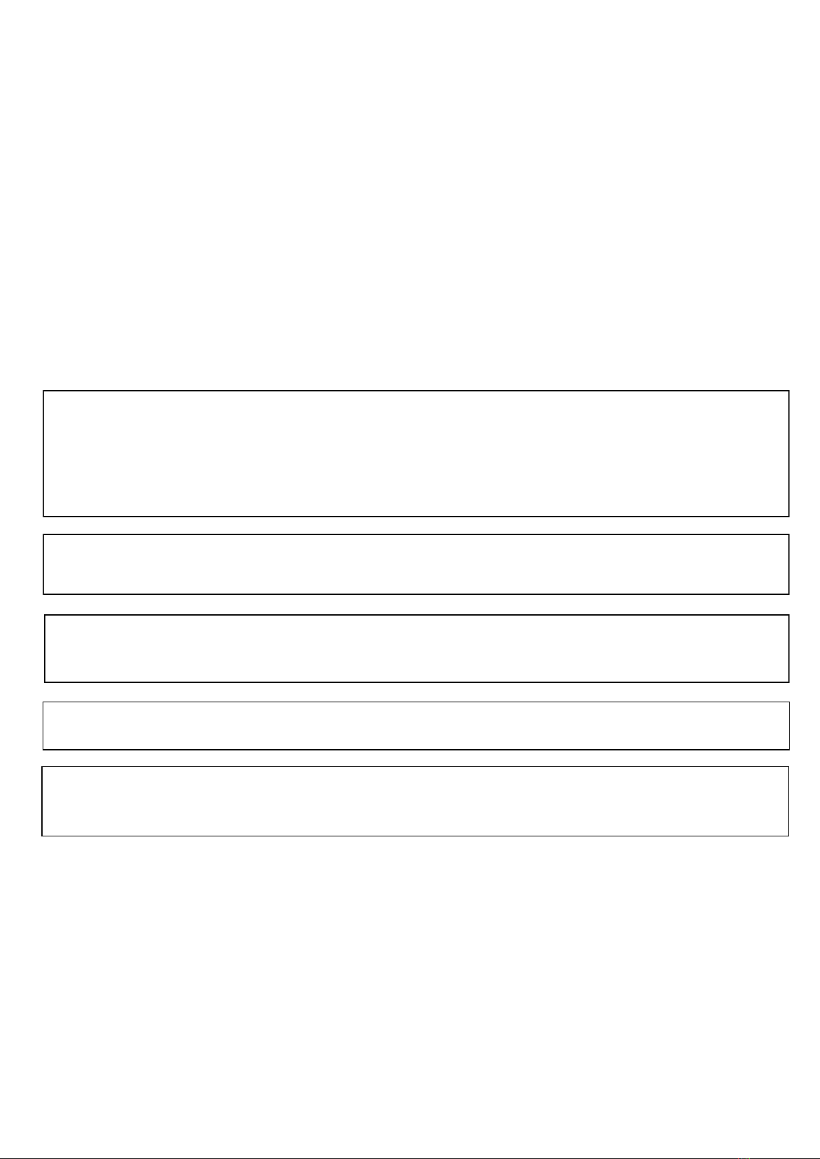
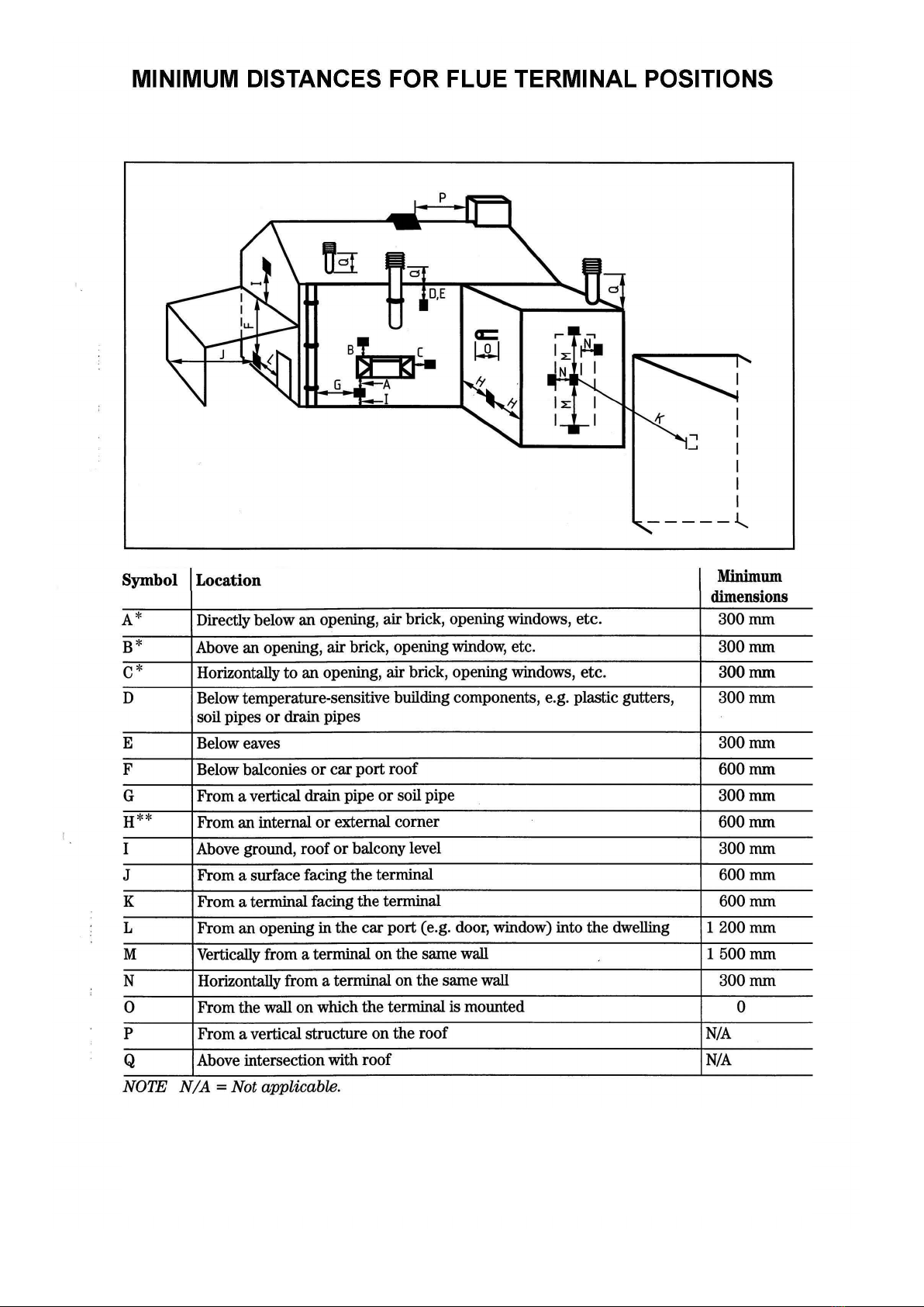
a. A feature of the Thermostatic Thermatronic Handset is it as a Battery Charge Indicator shown in the screen on the
Handset which will determine when both the Handset and Receiver Batteries need changing, however also see ‘b’.
b. For Both Control systems, Battery replacement is recommended at the beginning of each heating season, or when an acoustic error
message sounds during ignition.
c. Error Message – Long signals (0.8 second tone – 0.2 second break) during ignition – probable cause - batteries in electronic
receiver box are nearly discharged.
d. Error Message – 5 second continuous tone – probable cause – cable disconnected or on/off switch on valve is in off position.
e. Batteries - Electronic Receiver Box - 4 x AA good quality alkaline - Handset - 1 x PP3 good quality alkaline.
f. To change the Handset battery slide open the plastic panel on the back of the Handset.
g. To change the Receiver Batteries open the outer door by pulling pull at the left side to release it from the magnetic catches.
Locate the electronic receiver box, underneath the fire on the left hand side. Slide open the plastic cover to gain access to the battery
compartment. You can detach the Receiver by pulling it off its Velcro Pad to make access easier but remember to put it back in the
same position.
Note: Only Change The Batteries When The Fire Is Cold
! WARNING! THE THERMOSTATIC THERMOTRONIC CONTROL SYSTEM PROVIDES THE MEANS FOR UNATTENDED
OPERATION OF THE FIRE IF THE PROGRAMS OR THERMOSTATE SETTINGS ARE USED THIS COULD POSE A DANGER IF
COMBUSTIBLE MATERIALS ARE TOO CLOSE TO THE FIRE OR IF YOUNG CHILDREN, THE ELDERLY OR INFIRM OR PETS
ARE LEFT IN ATTENDANCE.
3.5 - RESETTING THE MERTIK MAXITROL LOGIC CIRCUITS IF THE HANDSET DOES NOT WORK - APPLIES TO
BOTH CONTROL SYSTEMS
Must only be done when the fire is Cool
Basic Reset - It sometimes happens that (such as when the handset buttons are pressed out of sequence) the fire stops
working because the logic circuits get confused and need to be reset.
To do this, simply remove the 4 x AA batteries from the Receiver Box (see section 2.4f above), wait for 1 minute and then refit the
batteries. Wait for another minute and then point the handset at the fire and press the red/off button. Wait for another minute and then start
the fire as normal. If the fire does not start repeat the resetting procedure. If the fire still does not work a Full Reset can be tried.
Full Reset - If you obtain a new handset the control system will need to learn the handset’s unique code via a Full Reset. Also, if the fire is
not working and the Basic Reset has not worked a Full Reset can be carried out:
Open the outer door by pulling at the left side to release it from the magnetic catches and open the outer door, locate the electronic Receiv-
er Box.
Locate the Reset Hole on the side of the Receiver and using a pen press and hold in the Reset button until you hear two beeps.
The first beep is short and the second beep is long. After the second beep release the Reset Button.
Now on the Handset, within the next 20 seconds press and hold the Small Flame Button until you hear two additional short beeps
confirming the code is set in the Receiver.
If you hear one long beep the Code as not been set so repeat the procedure.
If after carrying out the above procedure the situation is not corrected it will be necessary to contact your Installer.
Note: For the Installation/Service Engineer - Resetting of the Handset & Control System is also covered in Section 19.1 page 30.
4.0 - CLEANING THE FIRE
a. Allow to cool before cleaning.
b. The outside of the glass can be cleaned as follows:
Clean glass using (preferably distilled) water and a soft cloth ensuring the glass is dried thoroughly afterwards, again using a soft cloth.
If stubborn marks persist use a purpose produced Ceramic hob cleaner to clean the area again using a soft cloth.
Under no circumstances must an abrasive cleaner be used as this will scratch the glass.
c. It is quite normal for soot to build-up on the inside of the glass panel over time.
The inside of the Glass Door can be cleaned as follows:
Open the outer door, by pulling on the centre of the left hand side.
Using the Pozidriv screwdriver provided unscrew the 2 screws to the Left Side of the door.
Follow instructions in section b. above.
d. The logs or driftwood must not be cleaned or moved.
e. The outer surfaces of the fire can be cleaned with a damp cloth, do not use abrasive cleaners.
! IMPORTANT NOTE ! Under no circumstances must the fire be operated without the glass door being fully closed and secure.
5.0 - SERVICING
a. The fire should be Serviced Annually in accordance with the Gas Safety & Uses Regulations.
b. This fire contains no User Serviceable Parts apart from the batteries.
c. Servicing must be carried out by a Registered Installer.
d. For Servicing or Spare Parts contact your Installer quoting the Fire Name, Model and Serial Number, which can be found on the Data
Badge. To find the Data Badge/Plate; with the fire cool open the outer door, the Data Badge/Plate can be found at the base next to the
Control.
e. In the event that the fire shuts down due to any reason, attempt to restart it. If there is a continuing problem, call in a properly
qualified specialist engineer.
f. Under No Circumstances must this fire be used if the Glass Panel is broken damaged or cracked or if the Door Seal is
damaged

9
INSTALLATION & SERVICE INSTRUCTIONS
6.0 - INSTALLATION REQUIREMENTS
THIS APPLIANCE MUST BE INSTALLED AND SERVICED BY A PROPERLY QUALIFIED, (IN ACCORDANCE WITH LOCAL &
NATIONAL CODES), INSTALLATION ENGINEER.
It is the Law in the UK that All gas appliances are installed by a competent person in accordance with the GAS SAFETY(INSTALLATION
AND USE ) REGULATIONS 1998 (As amended), the relevant British Standards for Installation work, Building Regulations, Codes of
Practice and these Instructions . In the UK a Registered Installer is deemed competent. In the Republic of Ireland, all Irish Standards,
Local Codes and Bord Gais recommendations should be adhered to.
The Installation should also be carried out in accordance with the following where relevant:
1. BS5871 Part2 2. BS5440 Parts 1& 2 3. BS6461 Parts 1&2 4. BS6891 5. BS8303
Building Regulations and Standards issued as relevant by the Department of the Environment or the Scottish Development Department.
In the Republic of Ireland Installation should be carried out in accordance with IS813, ICP3, IS327, Building Regulations, Codes of
Practice, these Manufacturers Instructions and any Rules In Force.
Particular Reference should be made to the Ventilation Requirements, for the UK this Appliance does not require any additional
purpose provided ventilation, for the Republic of Ireland ventilation should be in accordance with IS813 Domestic Gas Installations.
Failure to comply with the above could leave the Installer Liable to Prosecution and Invalidate the Warranty.
IMPORTANT : BEFORE PROCEEDING WITH THE INSTALLATION READ THESE INSTRUCTIONS CAREFULLY.
THESE INSTRUCTIONS SHOULD BE LEFT WITH THE USER FOR SAFE KEEPING AND FUTURE SERVICING.
PRIOR TO INSTALLATION ENSURE THAT THE GAS TYPE AND PRESSURE ARE AS STATED ON THE APPLIANCE DATA PLATE.
7.0 - APPLIANCE DATA
a. Gas Type: See Data Plate, (Natural Gas at 20mbar or Propane at 37mbar).
b. Burner Pressure: Natural Gas 19.1mbar hot Propane 36.6mbar hot
c. Control System: Thermatronic (Fully Sequential) Control System operated by Handset pointed at Receiver.
d. Fire Safety: Flame Failure Device & Delayed Ignition Device.
e. Ignition: Full Sequential Control.
f. Inlet Connection: 8mm Compression Fitting to Gas Isolation Elbow.
g. Category: I2H, I3P.
h. Injector: Natural Gas (G20)-510 Single hole. Propane (G31) - 210 Single hole.
i. Heat Input: High: Natural Gas (G20) - 6.4kW Gross (5.77kW Nett). Propane (G31) - 6.1kW Gross (5.61kW Nett).
j. Heat Input: Low: Natural Gas (G20) - 2.8kW Gross (2.52kW Nett) Propane (G31) - 2.8kW Gross (2.58kW Nett).
k. Efficiency Class: 1. The Efficiency of this appliance has been measured as specified in BS EN 613 and the results obtained
were 74.9% Gross (83.2% Nett) on Natural Gas and 74.9% Gross (83.2% Nett) on Propane. The tests data has been certified by
G L Industrial Services UK Ltd (0087) and can be used in the UK Government’s Standard Assessment Procedure (SAP) for
energy rating of dwellings.
l. Heat Output: High: Natural Gas (G20) - 4.8kW Propane (G31) - 4.67kW.
m. Heat Output: Low: Natural Gas (G20) - 1.7kW Propane (G31) -1.7kW.
n. Nitrous Oxide (NOx) - 130mg/kWh.
8.0 - APPLIANCE DIMENSIONS
8.1 The Diagram below shows the General Fire Sizes fitted with the Steel Door with Sealing Frame.
For other Door and for Frame Style Options see below.

10
8.2 The Synergy Perspective BF is available with various Trim Styles with Glass or Metal Door Options.
Some Styles also have a Sealing Frame Option (Normally used for Wall Mounted Installations).
The Synergy Perspective Echo Trim is Not Available for the Synergy Perspective BF.
The general dimensions are shown with a table below showing the minimum flat area required around the Fireplace Opening
The Synergy Perspective BF Steel & Glass Options can be supplied with or without the Sealing Frame for different applications.
The Synergy Perspective BF Steel can only be Installed below a Wall Mounted Television if Installed in a Suitable Fire Surround.
All other Trim Options can be Installed below a Wall Mounted Television be it in a suitable fire surround or wall mounted subject to
specific requirements which should be discussed with your Nu-Flame stockist and subject to the requirements in these Instructions.
The Side Views show how far the Trims project from the wall.
Minimum Flat Sizes for Doors & Frames (Central Around Opening)
Width (mm) Height (mm)
Synergy Perspective BF Steel Trim (No Sealing Frame) 1135mm 560mm
Synergy Perspective BF Steel Trim (With Sealing Frame) 970mm 630mm
Synergy Perspective BF Glass Trim (No Sealing Frame or Shelf) 980mm 550mm
Synergy Perspective BF Glass Trim (With Sealing Frame & Shelf) 980mm 605mm
Note: Where a the Synergy Perspective BF Steel or Glass Trims combinations is to be Installed in a Fire Surround a Riser Plate
Must have been specified which will raise the fire by 30mm to allow for the Metal or Glass Door to open clear of the Hearth.
Note: Where a the Synergy Perspective BF Glass Trim is to be Wall Mounted the Glass Shelf will be supplied and Must always
be fitted.
Note: This does not take account of any up stand that may be present around the Hearth for which a greater height allowance
may be required. More detail is provided in Section 15.
Synergy Perspective BF Glass
Available With or Without Sealing Frame
and/or Top Shelf
Synergy Perspective BF Steel
Available With or Without Sealing
Frame

11
9. FLUE & TERMINAL DETAILS & REQUIREMENTS
a. The Fire is supplied with a specially designed flue system and no other flue system can be used.
b. The Fire and Flue Terminal System must be sited in accordance with BS5440: Part 1. See diagram and table on page 5, which
shows Acceptable Flue Terminal Positions.
c. The Terminal Guard supplied with the fire MUST be used if there is free access to the area of the Flue Terminal.
d. The Flue Terminal will become VERY HOT when the fire is in operation.
e. The Flue caters for Walls up to a maximum of 500mm thick and minimum of 100mm thick.
f. In the majority of applications due to the Fire’s depth it will require building work, be it masonry or studwork. Section 12 shows
three options, one of which must be decided before proceeding.
10. VENTILATION
a. No additional purpose provided ventilation is required for the fire.
b. This appliance is fitted with a Flame Failure Safety system which automatically shuts off the gas supply if the flame goes out for
any reason. It must not be tampered with and only replaced with a genuine Nu-Flame Pilot Assembly.
11. GAS SUPPLY
It Is Recommended to Check The Next Section as Building Work May Affect the Gas Supply Routing.
a. Carry out a gas soundness test before working on the gas supply.
b. Gas supply provision should be made in accordance with the latest Gas Safety (Installation and Use) Regulations as amended.
c. Confirm that the fire has been supplied for the correct gas to be used by checking the Data Badge in the base of the fire.
d. A route for a concealed gas supply is provided through a hole in the rear of the fire, at a position of 165mm to the left of the
centre of the fire and 38mm up from the base of the Fireplace Enclosure. An isolation elbow is provided at the control inlet.
e. Where the gas supply passes through walls, floors, voids, concrete and wall cavities the supply should be sleeved.
f. Determine the gas supply pipe size required taking into account any other gas appliances.
g. Determine where the gas supply pipe needs to terminate and fit the 8mm compression isolation/pressure test elbow provided.
h. In common with all other gas appliances, dirt and debris in the gas system can block the valve and gas injectors on this
appliance, and faults caused by this are not covered by the guarantee.
Therefore it is important that all gas pipes must be purged of both air and debris.
i. If you suspect that there may still be dirt and/or debris in the gas system, fit a filter in the pipeline, before the gas isolation/
pressure test elbow.
j. Do not use jointing compound on any compression fittings on the fire. The use of jointing compound on the compression joints
on this appliance will possibly invalidate the guarantee, as it can get into the control mechanism and cause a malfunction.
k. Seal off the isolation/pressure test elbow and check all gas connections for gas soundness before proceeding to fit the fire.
! IMPORTANT NOTE ! Always reseal the pressure test point and check that it is gas tight. (This accounts for a lot of recalls.)

12
INSTALLATION OPTIONS
VERY IMPORTANT
ALL RELEVANT SECTIONS SHOULD BE CONSIDERED BEFORE ANY BUILDING WORK.
The Installation Options Are:
12.0 Hole in the Wall Installation For Steel & Glass Trims (using Sealing Frames) - Options:
Requirements for Builders Opening and Combustible or Non Combustible Shelves.
13.0 Hole in the Wall Installation (when using marble, slate or stone slips) - Options:
Requirements for Builders Opening and Combustible or Non Combustible Shelves.
14.0 Fire Surround Installation - Options:
Requirements for Builders Opening and Combustible or Non Combustible Shelves/Mantels.
15.0 Installation for a Wall Mounted Televisions - With Options Above.
Note: The Steel Trim Option Cannot Be With A Wall Mounted Installation.
However It Can Be Used In A Fire Surround Installation.
With A Fire Surround Installation the Shelf of the Fire Surround directs the heat away from the Television Area.
However please note the additional Nu-Flame Television Heat Shield will still be required.
Sections 12 - 15 Detail Various Installation Options - Only one will apply.
! IMPORTANT NOTE !
The chosen installation should have been predetermined
with any parts ordered before any Building Work Is Started or Installation of the fire.
If a Wall Mounted Television is Being Considered Read Section 15 First.
Important - the chosen installation and correct parts
should have been predetermined and ordered with the fire.
Ensure you refer to the section relevant to your requirement.

13
12.1 - SEALING FRAMES & WALL COVERINGS
With any form of heating appliance convection air will rise up through the fire carrying particles of dust that will in time result in
varying degrees of wall staining. The Nu-Flame Sealing Frames (& for Perspective Glass the Glass Shelf) are designed to minimise this by
deflecting the airflow away from the wall. However, over time some staining might occur and we therefore suggest not using patterned
paper around the fire.
Due to the heat output of The Synergy Perspective BF it is not recommended to use blown vinyl wall covering around the fire.
12.2 HOLE IN THE WALL APPLICATION (USING NU-FLAME SEALING FRAMES)
FIREPLACE ENCLOSURE
a. The fire can be installed in a suitably sized Masonry Fireplace Enclosure or suitable studwork construction, see diagrams.
b. It is recommended that a qualified builder or joiner constructs the Fireplace Enclosure.
c. For Masonry Constructions it is recommended that a lintel is fitted above the Fireplace opening. A structural survey may be
Required.
d. For Combustible Installations (e.g. Wood-Studwork) the Fireplace should be lined with a suitable non combustible material
e.g. Superlux Board.
If the rear wall is also Combustible the Fire back must also be insulated.
e. No combustible materials (e.g. Wood-Studwork) must be closer than 50mm to the fire and therefore the size of the Fireplace
should cater for this, see diagram for minimum sizes. The Front Opening sizes should be as shown in the diagram.
f. The base of the fireplace enclosure must be flat, level and square to the wall and it MUST be strong enough to support the fire.
g. Where the cavity forms part of the Fireplace Enclosure this MUST be Sealed off with either a Non Combustible Material or with
a Combustible Material set at least 50mm away from the Fire. Note: A drip/weather shield or equivalent should be provided
above the Fireplace Enclosure to prevent rain/damp bridging the cavity.
h. A Hole for the flue should be centrally cut at a height of 540mm from the base of the Enclosure. See Cutting the Hole.
i. The Fireplace Enclosure should have provision for a gas supply through the rear, see Section 10 Gas Supply.
j. There must be a flat surface around the face of the Fireplace opening of at least 100mm above, 125mm at each side and 30mm
at the base. This is essential in order to achieve a good seal between the wall and the sealing frame.
k. The recommended height for the base of the Fireplace Enclosure is 350mm above floor level. The minimum height for the base of
the Fireplace Enclosure is 250mm above floor level.
l. The fire is fitted with Electronic Equipment, which is sensitive to dampness and high humidity so it is very important that any
rendering/building work is allowed to thoroughly dry out before installation
! IMPORTANT ! Dry lined walls – ensure that any air gaps between the back of the plasterboard and wall are sealed
around the fireplace enclosure or fireplace as this can affect the fires efficiency and cause wall staining.
12.0 - HOLE IN THE WALL APPLICATION (USING NU-FLAME SEALING FRAME)
ONLY FOR SYNERGY PERSPECTIVE BF WITH STEEL & GLASS STYLE WITH SEALING FRAME
NOTE: THE STEEL TRIM STYLE CANNOT BE WALL MOUNTED WITH A WALL MOUNTED TELEVISION HOWEVER
THE GLASS TRIM STYLE WITH GLASS SHELF & TV SHELF ARE SUITABLE SEE SECTION 16
FIREPLACE ENCLOSURE, HOLE POSITION, SIZING, CUTTING THE FLUE & FITTING THE FIRE.
The Flue Length & Height of Flue Hole May Be Different For Each Application.
If A Wall Mounted Television Is Being Considered Read Section 15 First.
FIREPLACE ENCLOSURE FOR MASONRY HOLE
IN THE WALL APPLICATION
(USING NU-FLAME SEALING FRAME)
FIREPLACE ENCLOSURE FOR COMBUSTIBLE
HOLE IN THE WALL APPLICATION
(USING NU-FLAME SEALING FRAME)

14
12.3 - CLEARANCES TO SHELVES & COMBUSTIBLE MATERIALS
a. We do not recommend the use of combustible shelves in this application.*
We do not recommend the use of a non-combustible shelf in this application.*
However, see section 13 which shows the application where a non-combustible shelf is used.
c. Any combustible sidewall must be at least 500mm from the inside of the Fireplace opening.
d. With all heating appliances, soft furnishings, decorations and wall coverings may discolour or scorch if placed too close.
e. No combustible material, e.g. curtains must be closer than 500mm to the fireplace enclosure..
*The wall between the sealing frame and any shelf would become hot. Therefore, we do not recommend any shelves with this type of instal-
lation.
12.4 - CUTTING THE HOLE FOR THE FLUE
The flue is 150mm in diameter, and a hole is required providing sufficient clearance. The following Notes will assist:
a. If cutting the hole with a core drill ensure the pilot hole is cutting into solid material as it may wander.
b. Partially drill or cut out the hole and then check the fit of the flue before finishing.
c. Ensure the hole is horizontal, round and straight.
d. Make good the hole on both the inside and outside (a Wall Plate is provided for the outside).
e. Any Cavity Wall insulation must be trimmed and sealed back from the hole by at least 50mm to prevent contact with the flue.
12.5 - PREPARING THE FLUE
a. The Flue Length supplied caters for a Maximum Flue Length of
500mm, and a Minimum Flue Length of 93mm.
(Total Flue Length of flue supplied Including Terminal = 630mm).
b. To find the flue length required in your application ; measure the
Depth from the front face of the Fireplace to the Outside Wall. For the
Fire with Sealing Frame deduct 343mm or without Sealing Frame deduct
359mm (ref page 9) from this dimension; this will provide the flue length
for your application.
Take your flue length dimension from 500mm, (maximum wall flue
length provided), and this is the length you will need to cut off the flue.
See Diagram with Example.
c. From the open end of the flue mark the cut off dimension, position the
cutting aid in the flue central about the cut line and cut the flue,
ensuring it is cut square; remove any sharp edges.
Remove the Cutting Aid Material from inside the Flue.
d). With the flue at the correct length and when the fire is fitted there should be 130mm of Flue Terminal Outside The Wall and
the screw holes for fixing the Wall Plate should line up with those in the Flue Terminal. See photographs on next page
! IMPORTANT NOTE ! NONE OF THE SQUARE HOLES IN THE FLUE TERMINAL MUST BE WITHIN THE WALL.
! TIP ! To provide a good square cut end to the flue, working form the Open end of the flue; place 5 marks around the flue
and using a tape measure coiled around the flue mark a continuous line.
! IMPORTANT NOTE ! Numerous problems occur because the cutting aid is not removed after cutting the flue.
! IMPORTANT NOTE ! Numerous problems occur because the correct length of the flue is not first determined and the
square cut outs in the flue terminal are not outside the flue. Check that the Wall Plate screws can
be fitted into the Flue.
! IMPORTANT NOTE ! Do NOT FORCE the flue when engaged into the flue spigot; it goes in just 40mm up to a stop and
will block off the flow creating a poor flame picture and overheating if pushed in too far.
FLUE LENGTH DIAGRAM - EXAMPLE
Depth for Fire used with the Sealing Frame = 343mm
Inside Wall to Outside Wall Dimension = 595mm
Deduct the Appropriate Fire Depth:
595mm – 343mm = 252mm
Take this from the 500mm Flue Length Supplied:
500mm – 252mm = 248mm.
Cut 248mm off the Open End of the Flue
NOTE: The Depth of the Fire can be different .
Check Which Application Applies on Page 9.

15
12.6 FITTING THE FIRE & USING THE CABLE FIXING SYSTEM - reference should be made to the drawings on the
next page
a. A cable fixing system is supplied for securing the fire. For Masonry Applications screw fixing may be considered and holes are
provided in the Sealing Frame.
b. There is silicone sponge sealing strip already affixed to the relevant surfaces to ensure a good seal. Ensure this silicone sealing
strip stays in place during installation.
c. A cable fixing system is supplied to secure the unit into the Fireplace Enclosure. The cable fixing system will also pull the unit
tight back against the wall to make a good seal. This is very important to ensure efficient operation of the fire.
d. There are 2 cables supplied; 1 to be used each side of the unit. Working at 730mm centres in the fireplace enclosure drill the
lower holes 20mm up from the base and drill the higher holes 610mm up from the base - see drawing on below. Secure the 4
Eyebolts supplied with the Rawlplugs to the back of the fireplace. Ensure the Eyebolts are fully screwed in and protrude no more
than 25mm.
e. There are 2 cable attachment points on the top of the main casing; 1 each side at the rear. They are part of the folded lip of the
top section prize these up with a screwdriver to enable them to be used. Feed a cable downwards through each cable
attachment point ready for installing the fire
f. Push the Flue onto the Spigots at the rear of the fire and IMPORTANT, ensure that ‘TOP’ marked on the end of the Flue
Terminal is at the top centre ; using the drill provided and with the flue level mark and drill the three holes around the Spigot.
Secure the flue with the Screws provided and then seal around the flue/spigot with the Sealing Tape also provided.
IMPORTANT : Do Not Force The Flue In Too Far Or Past It’s Stop As It Will Block Off The Flow Causing Overheating.
g. Rest the Fire in the Fireplace opening so that you can still gain access to the cables and eyebolts. Feed the cables though the
eyebolts on either side and then through the hole in the back of the fire near the base
h. Slide the Fire/Flue into the Fireplace guiding the flue into the hole until it is part way (leaving the fire sticking out approximately
50mm) ensuring the gas supply pipe and isolation/pressure test elbow clears through the cut out in the rear of the Main Casing
and does not foul on the control.
i. Lift the Fire slightly and slide it home ensuring that the sealing strips on the underside of the front of the Fire and around the
flange of the Sealing Frame stay in position to create a seal to the wall around the fireplace opening. While sliding the unit into
the Fireplace Opening pull on the excess cable.
j. Referring to the illustrations on the next page feed the cables through the two loose cable clamp brackets. The adjuster and lock
screw can now be fitted onto the cable and through the large hole in the cable clamp bracket. Position the brackets one either
side of the fire towards the bottom of the channel between the Main Casing and the Inner Fire Casing. By use of the adjuster
and lock screw tighten up the cable to tension the fire back into the fireplace. The fire should be secure and not liable to
movement.
Surplus fixing cable MUST NOT be cut off and must be tucked back through the small hole in the cable clamp bracket to keep it
well away from any electronics.
k. If any of the silicone sealing strips are not compressed and/or if there are gaps they must be filled with a suitable sealant, fireclay
or high temperature silicone.
l. Now on the Outside check that the End Terminal part of the Flue is clear of the hole = 130mm of Flue, the Terminal should be
clear of the wall – NOT WITHIN THE WALL. See photograph below.
m. Fit and secure the Wall Plate to the Flue through the holes provided in the flue terminal and seal to the Wall with the Stainless
Steel Screws provided.
Note: To prevent the ingress of water Sealing Foam has been supplied for the Wall Plate, if this does not provide an adequate
seal with the wall then any gaps must be filled with a waterproof silicone sealant or mastic.
Note: With the flue at the correct length and when the fire is fitted there should be 130mm of Flue Terminal Outside The Wall
and the screw holes for fixing the Wall Plate should line up with those in the Flue Terminal.
n. Connect the isolation/pressure test elbow to the control valve and with it fully open check the joint for gas soundness.
o. Check that all gas connections are sound. The appliance has been factory tested; however the connections may have been
disturbed in transit or storage.
! TIP ! If the Burner needs to be removed first pull both the Electronics Control Box and Infrared Sensor off their Velcro
mountings. Take out the 6 self-tapping screws securing the burner mounting plate, then taking care not to catch
the soft firebox linings and lifting at the rear, swing the whole assembly out and clear of the fire taking care not to
damage the liner panels, which are soft and can easily be marked. Take care and ensure the Receiver and
Sensor do not catch on the fire as they are removed .
! IMPORTANT NOTE ! Always reseal the pressure test point and check that it is gas tight.
(This accounts for a lot of recalls.)

16
12.7 - PROCEED TO SECTION 15 - ARRANGEMENT OF THE FUEL EFFECT
FIREPLACE ENCLOSURE – HOLE CENTRES
FOR CABLE FIXING SYSTEM EYEBOLTS
NOTE: Tensioning
nut wound fully back
to allow maximum
adjustment
FINISHED & ADJUSTED
Do not overtighten -
just enough to seal

17
This Hole in the Wall Application is suitable for all Trim Models without a Sealing Frame however for
the Synergy Ellesse Glass Trim Option the Glass Shelf Must be used.
This Hole in the Wall Application does not use the Nu-Flame Sealing Frames.
13.1 - SLIPS & WALL COVERINGS
It is essential to use marble, slate or stone slips, fitted around the fireplace opening. The slips must have a temperature rating of
150ºC and we recommend that they form a border around the fire of at least 100mm. In order to direct the flow of heated air away
from the wall we recommend that a non combustible shelf (lip) is fitted above the top slip, protruding 30mm – see diagram at end of
section 12.6.
With any form of heating appliance convection air will rise up through the fire carrying particles of dust that will in time result in
varying degrees of wall staining. The non-combustible shelf is designed to minimise this by deflecting the airflow away from the wall.
However, over time some staining might occur and we therefore suggest not using patterned paper around the fire.
Due to the heat output of The Synergy Perspective BF it is not recommended to use blown vinyl wall covering around the fire.
Where the Chimney Breast is made of Stone or Slate or other Suitable Non Combustible Material with NO wall coverings then Slips
are Not Required but the Dimensions of the Fireplace Enclosure must be as shown below and a Flat Surface of at least 50mm must
be provided around the opening for sealing.
In this Application as Slips are being used we supply a Cable Fixing System as Drill Fixing may cause cracking of the slips, which
may not show until the fire as got hot and then cooled down over a number of operations.
Nu-Flame will not accept responsibility for Cracked Slips due to Drill Fixing
13.2 HOLE IN THE WALL APPLICATION (WHEN USING MARBLE SLATE OR STONE SLIPS)
BUILDING ENCLOSURE
a. The fire can be installed in a suitably sized Masonry Fireplace Enclosure or suitable studwork construction, see diagrams.
b. It is recommended that a qualified builder or joiner constructs the Building/Fireplace Enclosure.
c. For Masonry Constructions it is recommended that a lintel is fitted above the Fireplace opening. A structural survey may be
Required.
d. For Combustible Installations (e.g. Wood-Studwork) the Fireplace should be lined with a suitable non combustible material
(e.g. Superlux Board or Equivalent).
If the rear wall is also Combustible the Fire back must also be insulated.
e. No combustible materials (e.g. Wood-Studwork) must be closer than 50mm to the fire and therefore the size of the Fireplace
should cater for this, see diagram for minimum sizes. The Front Opening sizes should be as shown in the diagram.
f. The base of the fireplace enclosure must be flat, level and square to the wall and it MUST be strong enough to support the fire.
g. Where the cavity forms part of the Fireplace Enclosure this MUST be Sealed off with either a Non Combustible Material or with
a Combustible Material set at least 50mm away from the Fire. Note: A drip/weather shield or equivalent should be provided
above the Fireplace Enclosure to prevent rain/damp bridging the cavity.
h. A Hole for the flue should be centrally cut at a height of 540mm from the base of the Enclosure. See Cutting the Hole.
i. The Fireplace Enclosure should have provision for a gas supply through the rear, see Section 10 Gas Supply.
j. There must be a flat surface around the face of the Fireplace opening of sufficient area to enable the slips to be fitted. The slips
must be square to the fireplace enclosure.
k. The recommended height for the base of the Fireplace Enclosure is 350mm above floor level. The minimum height for the base of
the Fireplace Enclosure is 250mm above floor level.
l. The fire is fitted with Electronic Equipment, which is sensitive to dampness and high humidity so it is very important that any
rendering/building work is allowed to thoroughly dry out before installation.
! IMPORTANT ! Dry lined walls – ensure that any air gaps between the back of the plasterboard and wall are sealed
around the fireplace enclosure or fireplace as this can affect the fires efficiency and cause wall staining.
! IMPORTANT ! When fitting the slips ensure they are flush and form a flat surface around the fireplace opening.
13. HOLE IN THE WALL APPLICATIONS (WHEN USING MARBLE, SLATE OR STONE
SLIPS) - supplied with cable fixing system (see 13.3)
BUILDING ENCLOSURE, HOLE POSITION, SIZING & CUTTING THE FLUE & FITTING THE FIRE.
The Flue Length & Height of Flue Hole May Be Different For Each Application.
If A Wall Mounted Television Is Being Considered Read Section 15 First.

18
13.3 - CLEARANCES TO SHELVES & COMBUSTIBLE MATERIALS
a. We do not recommend the use of a combustible shelf in this application.
b. We do not recommend the use of a non-combustible shelf in this application other than the non combustible shelf / lip mentioned
in section 13.6 page 20.*
c. Any combustible sidewall must be at least 500mm from the inside of the builders/fireplace opening.
d. With all heating appliances, soft furnishings, decorations and wall coverings may discolour or scorch if placed too close.
e. No combustible material, e.g. curtains must be closer than 500mm to the fireplace enclosure.
*The wall between the upper slip and any additional shelf spaced above the slip would become hot. Therefore, we do not
recommend any shelves space away from the slips.
13.4 – CUTTING THE HOLE FOR THE FLUE
The flue is 150mm in diameter, and a hole is required providing sufficient clearance. The following Notes will assist:
a. If cutting the hole with a core drill ensure the pilot hole is cutting into solid material as it may wander.
b. Partially drill or cut out the hole and then check the fit of the flue before finishing.
c. Ensure the hole is horizontal, round and straight.
d. Make good the hole on both the inside and outside (a Wall Plate is provided for the outside).
e. Any Cavity Wall insulation must be trimmed and sealed back from the hole by at least 50mm to prevent contact with the flue.
MASONRY FIREPLACE ENCLOSURE FOR HOLE
IN THE WALL APPLICATION (USING MARBLE,
SLATE OR STONE SLIPS)
THE EQUIVALENT FIREPLACE ENCLOSURE FOR
COMBUSTIBLE HOLE IN THE WALL
APPLICATIONS (USING SLIPS)

19
13.5 - PREPARING THE FLUE
a. The Flue Length supplied caters for a Maximum Flue Length of 500mm,
and a Minimum Flue Length of 93mm.
(Total Flue Length Including Terminal = 630mm).
b. To find the flue length required in your application; measure the
Depth from the front face of the Fireplace to the Outside Wall. For the
Fire with Sealing Frame deduct 343mm or without Sealing Frame deduct
359mm (ref page 9) from this dimension; this will provide the flue length
for your application.
Take your flue length dimension from 500mm, (maximum wall flue
length provided), and this is the length you will need to cut off the flue.
See Diagram with Example.
c. From the open end of the flue mark the cut off dimension, position the
cutting aid in the flue central about the cut line and cut the flue,
ensuring it is cut square; remove any sharp edges.
Remove the Cutting Aid Material from inside the Flue.
d. With the flue at the correct length and when the fire is fitted there should be 130mm of Flue Terminal Outside The Wall and the
screw holes for fixing the Wall Plate should line up with those in the Flue Terminal. See photograph on next page.
! IMPORTANT NOTE ! NONE OF THE SQUARE HOLES IN THE FLUE TERMINAL MUST BE WITHIN THE WALL.
! TIP ! To provide a good square cut end to the flue, working form the Open end of the flue; place 5 marks around the flue
and using a tape measure coiled around the flue mark a continuous line.
! IMPORTANT NOTE ! Numerous problems occur because the cutting aid is not removed after cutting the flue.
! IMPORTANT NOTE ! Numerous problems occur because the correct length of the flue is not first determined and the
square cut outs in the flue terminal are not outside the flue. Check that the Wall Plate screws can
be fitted into the Flue.
! IMPORTANT NOTE ! Do NOT FORCE the flue when engaged into the flue spigot; it goes in just 40mm up to a stop
and will block off the flow creating a poor flame picture and overheating if pushed in too far.
FLUE LENGTH DIAGRAM - EXAMPLE
Depth for Fire used with the Sealing Frame = 343mm
Inside Wall to Outside Wall Dimension = 595mm
Deduct the Appropriate Fire Depth:
595mm – 343mm = 252mm
Take this from the 500mm Flue Length Supplied:
500mm – 252mm = 248mm.
Cut 248mm off the Open End of the Flue
NOTE: The Depth of the Fire can be different .
Check Which Application Applies on Page 9.

20
13.6 FITTING THE FIRE USING THE CABLE FIXING SYSTEM - reference should be made to the illustrations on the
next page.
a. There is silicone sponge sealing strip already affixed to the relevant surfaces to ensure a good seal. Ensure this silicone sealing
strip stays in place during installation.
b. A cable fixing system is supplied to secure the unit into the Fireplace Enclosure. The cable fixing system will also pull the unit
tight back against the slips to make a good seal. This is very important to ensure efficient and safe operation of the fire.
c. There are 2 cables supplied; 1 to be used each side of the unit. Working at 730mm centres in the fireplace enclosure drill the
lower holes 20mm up from the base and drill the higher holes 610mm up from the base - see drawing on below. Secure the 4
Eyebolts supplied with the Rawlplugs to the back of the fireplace. Ensure the Eyebolts are fully screwed in and protrude no more
than 25mm.
IMPORTANT: ENSURE THE MATERIAL THE EYEBOLT/RAWPLUG IS FIXED INTO IS SOLID AND SOUND. If the fixing is
not sound the Rawlplug/Eyebolt will be pulled out and the fire will not be sealed to the Fireplace Opening.
Note: With the minimum depth fireplace enclosure it may be necessary to sink the Eye Bolt Heads into the Brickwork.
d. There are 2 cable attachment points on the top of the main casing; 1 each side at the rear. They are part of the folded lip of the
top section prize these up with a screwdriver to enable them to be used. Feed a cable downwards through each cable
attachment point ready for Installing the fire.
e. Push the Flue onto the Spigots at the rear of the fire and IMPORTANT, ensure that ‘TOP’ marked on the end of the Flue
Terminal is at the top centre; using the drill provided and with the flue level mark and drill the three holes around the Spigot.
Secure the flue with the Screws provided and then seal around the flue/spigot with the Sealing Tape also provided.
IMPORTANT : Do Not Force The Flue In Too Far Or Past It’s Stop As It Will Block Off The Flow Causing Overheating.
f. Taking care to not damage the slips, rest the Fire in the Fireplace opening so that you can still gain access to the cables and
eyebolts. Feed the cables though the eyebolts on either side and then through the hole in the back of the fire near the base
g. Slide the Fire/Flue into the Fireplace guiding the flue into the hole until it is part way (leaving the fire sticking out approximately
50mm) ensuring the gas supply pipe and isolation/pressure test elbow clears through the cut out in the rear of the Main Casing
and does not foul on the control.
h. Lift the Fire slightly and slide it home ensuring that the sealing strips on the underside of the front of the Fire and the rear of the
Fire outer frame stay in position to make a seal against the top edge of the slip at the base of the fireplace enclosure and the
front face of the slips where they locate against the rear of the Fire outer frame. While sliding the unit into the Fireplace Opening
pull on the excess cable.
i. Referring to the illustrations on the next page feed the cables through the two loose cable clamp brackets. The adjuster and lock
screw can now be fitted onto the cable and through the large hole in the cable clamp bracket. Position the brackets one either
side of the fire towards the bottom of the channel between the Main Casing and the Inner Fire Casing. By use of the adjuster
and lock screw tighten up the cable to tension the fire back into the fireplace. The fire should be secure and not liable to
movement.
Surplus fixing cable MUST NOT be cut off and must be tucked back through the small hole in the cable clamp bracket to keep it
well away from any electronics.
j. If any of the silicone sealing strips are not compressed and/or if there are gaps they must be filled with a suitable sealant, fireclay
or high temperature silicone.
k. Now on the Outside check that the End Terminal part of the Flue is clear of the hole = 130mm of Flue, the Terminal should be
clear of the wall – NOT WITHIN THE WALL.
l. Fit, and secure the Wall Plate to the Flue through the holes provided in the flue terminal and seal to the Wall with the Stainless
Steel Screws provided.
Note: To prevent the ingress of water Sealing Foam has been supplied for the Wall Plate, if this does not provide an adequate
seal with the wall then any gaps must be filled with a waterproof silicone sealant or mastic.
Note: With the flue at the correct length and when the fire is fitted there should be 130mm of Flue Terminal Outside The Wall
and the screw holes for fixing the Wall Plate should line up with those in the Flue Terminal.
m. Connect the isolation/pressure test elbow to the control valve and with it fully open check the joint for gas soundness.
n. Check that all gas connections are sound. The appliance has been factory tested; however the connections may have been
disturbed in transit or storage.
! TIP ! If the Burner needs to be removed first pull both the Electronics Control Box and Infrared Sensor off their Velcro
mountings. Take out the 6 self-tapping screws securing the burner mounting plate, then taking care not to catch
the soft firebox linings and lifting at the rear, swing the whole assembly out and clear of the fire taking care not to
damage the liner panels, which are soft and can easily be marked. Take care and ensure the Receiver and
Sensor do not catch on the fire as they are removed .
! IMPORTANT NOTE ! Always reseal the pressure test point and check that it is gas tight.
(This accounts for a lot of recalls.)
Table of contents
Other Nu-Flame Heater manuals