NuAire Ecosmart ES-ISC Series Instruction Manual

1
nuaire.co.uk 029 2085 8400 12. 12. 17. Leaflet Number 671432
The EMC Directive
2014/30/EU
The Low Voltage
Directive
2014/35/EU
ES-ISC
Ecosmart Speed Control
Installation and Maintenance
Always handle with care to avoid damage and distortion, and where
lifting slings are employed use spreaders to ensure slings do not come
into contact with the unit case, or control pack (see fig. 2).
2.2 Dimensions (mm) & Weights (Kg)
Control sizes are selected by matching the unit full load current with
the control code i.e. control code ES-ISC3.3A is suitable for a fan with a
maximum full load current of 3.3A.
The Inverter overload is pre-set at the rating plate value, if a lower
setting is required fit an appropriately sized overload relay to the output
contactor and adjust accordingly.
1.0 INTRODUCTION
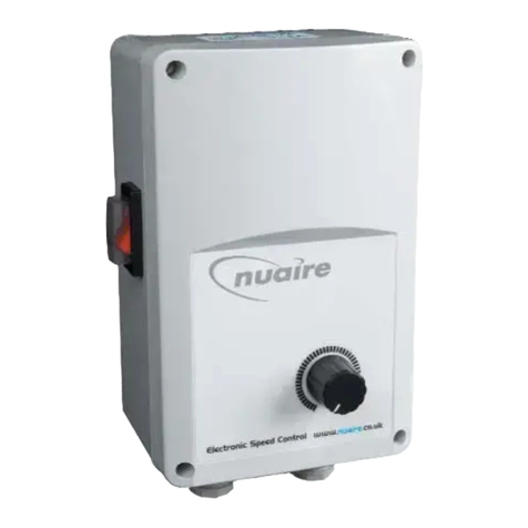
ES-ISC Ecosmart Controls
The Ecosmart Energy Saving Speed
Control is designed to control selected
Nuaire fans and to match the range of
integrated Ecosmart control systems.
The control is only available for
three phase electrical supply.
The case material is of Aluzinc corrosion
resistant steel, incorporates a frequency
inverter, Ecosmart control board and is
directly compatible with the Ecosmart
range of user controls, time clocks, ‘stats
and sensors.
Figure 1. Ecosmart Speed
Control
2.0 DELIVERY & RECEIPT OF EQUIPMENT
All equipment is inspected prior to despatch and leaves the factory in
good condition. Upon receipt of the equipment an inspection should be
made and any damage indicated on the delivery note.
Particulars of damage and/or incomplete delivery should be endorsed
by the driver delivering the goods before offloading by the purchaser.
No responsibility will be accepted for damage sustained during the
offloading from the vehicle or on the site thereafter.
All claims for damage and/or incomplete delivery must be reported to
Nuaire within two days of receipt of the equipment.
2.1 Offloading & Handling
The weight of the unit modules and palletised items are displayed on
the packaging.
Some of the modules have an uneven weight distribution, and this will
be indicated by labelling where appropriate.
Offloading and positioning of the equipment is the responsibility of
the purchaser. Items should only be lifted by competent personnel
following appropriate risk assessment.
Assembly with
base frame
Palletised
Forklift
Slings via spreaders fitted to unit
with base frame.
Please note that above images are
examples of typical lifting methods.
Actual unit lifting plan and risks
must be assessed by competent
personnel before moving the unit.
Figure 2. Typical
lifting methods.
Unit Code A B C Weight Drill Pattern
D E
ES-ISC1.2A 230 325 410 6 340 298
ES-ISC2.4A 230 325 410 6 340 298
ES-ISC3.3A 230 325 410 6 340 298
ES-ISC4.1A 230 325 410 6 340 298
ES-ISC5.6A 290 390 455 14 470 373
ES-ISC7.3A 290 390 455 14 470 373
ES-ISC8.8A 290 390 455 14 470 373
ES-ISC12.5A 290 390 455 20 470 373
ES-ISC15.6A 290 390 455 20 470 373
ES-ISC23.1A 290 390 455 20 470 373
ES-ISC38.0A 355 525 805 40 710 510
3.0 INSTALLATION
The installation must be carried out by competent personnel in
accordance with the appropriate authority and conforming to all
statutory and governing regulations i.e. IEE, CIBSE, HVCA etc.
The Ecosmart control is desgined to be installed indoors, away from
any water spray or steam generating source. Fix or mount in upright
position to a secure vibration free vertical surface (see fig. 1 & 3). Ensure
the ventilation grilles are free of obstruction.
If the unit is installed outdoors, the matching size weathering cover
ES-ISC-WP* must be used to provide weather protection.
E
A
C
D/2
D/2
B
D
Figure 3. Dimensions and drill pattern.

2
nuaire.co.uk 029 2085 8400 12. 12. 17. Leaflet Number 671432
Installation and Maintenance ES-ISC Ecosmart Speed Control
3.1 Mechanical Installation
For ease of installation, remove the front cover and disconnect any
cooling fans fitted. Remove the control casing from the base, offer the
base to the wall (or mark from the drill pattern).
Drill and fix the base to the wall using appropriate fasteners. It may be
easier to connect the field wiring at this stage. Reassemble the case
ensuring that cooling fans are reconnected.
IMPORTANT
The operating range is 0°C to 35°C, up to 85% relative humidity
(non-condensing).
Installation in unventilated loft is not recommended.
IMPORTANT
Isolation - Ensure that the unit is electrically isolated from the mains
supply before commencing work.
Motors of 4kW and above must be connected to Delta ∆
The screening of the power cable must be continuous. Bridge any
breaks (e.g. at local isolators) using braided earthing cable. Ensure the
screening is earthed at both ends.
IMPORTANT
To minimise the possibility of Electro Magnetic interference:
•Always install screened cable between the control and the fan,
maximum length 30 metres. Consult Nuaire if a longer cable run is
needed.
•This product must be earthed and always ‘earth’ the screened cable
at both ends. Ensure that ALL earth connections are the same
potential. Cable glands are provided.
•Always keep mains supply cables and motor supply cables separate
and DO NOT install any data cable or low voltage cable in the same
containment as mains carrying cables.
3.2 Electrical
The mains power supply to the controller must be appropriately sized
and installed via a local isolation switch (by others). The isolator must
also accommodate the 230V switched live (if used).
The mains supply from the Ecosmart controller to the fan must be
appropriately sized, not exceeding 30 Metres and must be a screened
power cable, earthed at both ends. A four point glanding plate is
formed from the base of the control and in order to maintain EMC
compliance, an EMC glanding kit is supplied.
Ecosmart controls and sensors are supplied with 10 metres of data
cable plugged at both ends, if used these can now be fitted and plugged
in to the low voltage sockets on the Ecosmart control board.All other
low voltage connections i.e. BMS can also be completed.
N
L
SL
Remove this link wire if:
1. A switched live signal is connected.
2. An ES-PIR, ES-LCD or BMS signal is connected.
Max SL run on Min
Trickle Test
10
Pwr
Standby
Fan 1
Fan 2
Heating
Cooling
Fault
Frost
Tx
Rx
Ecosmart
Earth
FAULT RUN
DAMPER
E L3L2 N L1
E N L1 L2 L3
Mains supply connections
400V 50Hz 3ph + Neutral
via local isolator.
1 5 3
2 4 6
(U) (V) (W)
CONTACTER
A1
A2
0V
0-10V
BMS signal
'NET' connection
U V W E
DP
CL
Connections to fan via screened
power cable. Purpose made glands
are provided to earth the screening.
N
RET
Note: Internal connections
between the supply terminals,
output contactors, the PCB and
inverter are made at the factory
Figure 4. ES-ISC wiring
diagram.

3
nuaire.co.uk 029 2085 8400 12. 12. 17. Leaflet Number 671432
Installation and Maintenance ES-ISC Ecosmart Speed Control
Figure 5. Volt free relay contacts.
4.0 CONTROL CONNECTIONS
4.1 Mains Connections
Mains cables should be suitably sized and terminated at the terminals
shown on the appropriate diagram.
4.2 Control Connections
4 IDC plug-in Net connectors are provided for the connection of
compatible sensors, manual controls and for linking the fans together
under a common control. If more than 4 connections are required,
the junction box (product code ES-JB) should be used (see data cable
installation).
Figure 6. 'Net'
connection for
Ecosmart devices.
4.3 Switched Live (SL) Terminal
A signal of 100-230V a.c. will activate the fan from either its off state
or trickle state (see setting to work-trickle switch). When the SL is
disconnected the fan will over-run for 1 – 60 minutes (see fig. 11).
Do not take this signal from an isolating transformer.
4.4 Damper Connections
Volt free contacts are not fused, if these are used to power any external
equipment, the installer must provide adequate fusing or other
protection. These contacts are rated at 5A resistive, 0.5A inductive.
OP - 230V 50Hz 1A max supply to open the damper
CL - 230V 50Hz 1A max supply to close the damper
N- Neutral supply to damper
RET - 230V ac return signal from the damper limit switch indicates the
damper has reached its operating position. If the return signal is not
present, the fan will wait for 1 minute before starting.
Note: If a damper is not fitted, connect a link wire from OP to RET. This
will cancel the delay.
The system’s response to a 0-10V dc BMS signal is given in the table
below.
Note the BMS signal will override any sensors and user control
connected in the system. The voltage tolerance is +/- 125mV and is
measured at the fans terminal.
N
E
L
SL
Remove link if switched live signal,
an enabler or BMS signal is connected.
Terminals or PCB
Mains connection pre-wired
230V 50Hz 1ph / 220V 60Hz 1ph
Figure 7. SL terminal.
RUN FAULT
Run signal Fault signal
Run Connections = Contacts are closed when the fan is running.
Fault Connections - No Fault = Contacts are closed.
Fault Connections - Fault = Contacts are open.
4.5 Data Cable Installation
A 4-core SELV data cable is used to connect devices.
Do not run data cable in the same conduit as the mains cables and
ensure there is a 50mm separation between the data cable and other
cables. The maximum cable run between any two devices is 300m
when it is installed in accordance with the instructions.
Please note that the total data cable length used in any system
must be less than 1000m. Keep the number of cable joints to a
minimum to ensure the best data transmission efficiency between
devices.
4.6 Maximum Number of Devices
The maximum number of devices (including fans) that can be
connected together via the cable is 32, irrespective of their functions.
4.7 Other Low Voltage Cables e.g. BMS signal
Follow the basic principle (as f). Keep the cable run as short as possible
but less than 50 metres. If the cable is longer than 12m, we recommend
using screened cable with the screening grounded at one end only
(preferably at the inverter end).
4.9 BMS input signals
The BMS connection is made with a
plug-in connector via the socket (see
fig. 9). To ensure the connection is made
only by suitably qualified and authorised
personnel the plug is not supplied.
It is available from R S Components,
Part No. 403-875 or Farnell, Part No.
963-021.
All wiring is 1Ph 230V 50Hz
230V
motor
S4
2
S6
1
RETOP CL N
All wiring is 1Ph 230V 50Hz
230V
motor
RETN OP CL
White Brown Blue
A fan starting
delay of 1 minute is
imposed to enable
the damper to open.
To override the delay
fit a link here.
A fan starting
delay of 1 minute is
imposed to enable
the damper to open.
To override the delay
fit a link here.
Figure 8. Drive open / spring close. Figure 9. Drive open / drive close.
IMPORTANT
Reversal of the BMS connection will damage the control.
4.8 Volt Free Relay Contacts
Volt free contacts are not fused, if these are used to power any external
equipment, the installer must provide adequate fusing or other
protection. These contacts are rated at 5A resistive, 0.5A inductive.
0 - 10V
0V
BMS
Figure 10. BMS input signals
IMPORTANT
Isolation - Ensure that the unit, switched live and Nuaire control are
electrically isolated from the mains supply before commencing work.
Inverter - When the fan is isolated, allow 5 minutes for the capacitors
in the inverter to discharge before commencing any work on the unit.

4
nuaire.co.uk 029 2085 8400 12. 12. 17. Leaflet Number 671432
Installation and Maintenance ES-ISC Ecosmart Speed Control
Ventilation Cooling mode * Heating mode *
Local Control 0.00 - -
OFF / Trickle 0.25 - -
Speed 1 0.50 0.75 1.00
Speed 2 1.50 1.75 2.00
Speed 3 2.50 2.75 3.00
Speed 4 3.50 3.75 4.00
Speed 5 4.50 4.75 5.00
Speed 6 5.50 5.75 6.00
Speed 7 6.50 6.75 7.00
Speed 8 7.50 7.75 8.00
Speed 9 8.50 8.75 9.00
Speed 10 9.50 9.75 10.00
*Only available on relevant unit
LED indicators
Min Max SL run on
Trickle Test
10
Pwr
Standby
Fan 1
Fan 2
Heating
Cooling
Fault
Frost
Tx
Rx
MIN = Minimum speed
adjustment
MAX = Maximum speed
adjustment
SL Run on = Switched Live Run-On
Timer adjustment
TRICKLE
= Selects trickle running:
0 = off, 1 = selected
TEST = Test button
Figure 11. Commissioning panel.
5.0 SETTING TO WORK
5.1 Electrical
5.1.1 Using the Test button
The test button allows the blower within the unit to be checked for its
operation. If the fan is running already, press the button once to stop
the fan, press again to switch on the fan.
Note that the fan will return to normal operation after 30 seconds.
5.1.2 LED Indication for Units with Ecosmart Control
PWR GREEN: Power on & OK.
RED: To much power is taken by peripherals or there is a short
circuit in the net cable. Check the cable and use a junction
box (ES-JB) to connect some of the peripherals.
Standby LED on when fan is not running.
Fan 1 GREEN: Fan 1 is running, RED: Fan 1 faulty.
Fan 2 GREEN: Fan 2 is running, RED: Fan 2 faulty (Twin fan only).
Heating* Not applicable. See note.
Cooling* Not applicable. See note.
Fault LED on when a fault is present on unit.
Frost* Applicable with LPHW only. See note.
Tx LED on when the controller is transmitting data.
Rx LED on when the controller is receiving data.
* Note that the control panel is common to all the Ecosmart
classic products and will have indicators for functions that are not
available in this particular fan. However these indicators will not
be illuminated.
5.2 Settings
5.2.1 Setting the Maximum Air Flow Rate
•Ensure the power supply is switched off and that a link wire is
connected from the supply L to the SL terminal. Unplug all items
connected to the ‘Net’ connectors.
•Switch on the power supply.
•Wait for the fan to reach steady condition.
Measure the airflow using standard commissioning instruments at a
suitable point in the ductwork. If adjustment is required, rotate the pot
marked ‘MAX’ to obtain the desired airflow. Remove the link wire if not
required - see “wiring (c)”.
5.2.2 Setting the Minimum / Trickle Air Flow Rate (Nomial 20%)
•Repeat the same procedure as for maximum airflow above but
without the link wire between supply L and SL terminal. Ensure the
trickle switch is in the ‘ON’ position. Adjustment must be made on
the pot marked ‘Min’.
•Note that the minimum setting (nominally 20%) must be
below the maximum setting; otherwise minimum setting will be
automatically set to be the same as the maximum.
•The minimum speed set is the trickle speed at which the fan
operates.
Note: The working speed range of the user control and sensors is
between the minimum and maximum set points.
6.0 MAINTENANCE
6.1 General Cleaning and Inspection
Clean and inspect the exterior of the unit, remove covers and carefully
clean out any dust deposits. Check security of all components and
terminals, remove fan filters and clean or replace as necessary. Refit
covers.
The first maintenance should be carried out three months after
commissioning and thereafter at twelve monthly intervals. These
intervals may need to be shortened if the unit is operating in adverse
environmental conditions, or in heavily polluted air.
6.2 Replacement of Parts
Should any component need replacing, Nuaire keep extensive stocks
for quick delivery. When ordering spare parts, please quote the serial
number of the unit and the ARC number of the purchase, if possible
(this information will be available on the fan label).
7.0 WARRANTY
The 5 year warranty starts from the day of delivery and includes parts
and labour for the first year. The remaining 4 years covers replacement
parts only.
This warranty is void if the equipment is modified without
authorisation, is incorrectly applied, misused, disassembled, or not
installed, commissioned and maintained in accordance with the details
contained in this manual and general good practice.
The product warranty applies to the UK mainland and in accordance
with Clause 14 of our Conditions of Sale. Customers purchasing from
outside of the UK should contact Nuaire International Sales office for
further details.
8.0 AFTER SALES ENQUIRIES
For technical assistance or further product information, including spare
parts and replacement components, please contact the After Sales
Department.
Telephone 02920 858 400
aftersales@nuaire.co.uk
This manual suits for next models
11
Table of contents
Other NuAire Controllers manuals