manuals.online logo
Brands
  1. Home
  2. •
  3. Brands
  4. •
  5. NuAire
  6. •
  7. Controllers
  8. •
  9. NuAire Ecosmart User manual

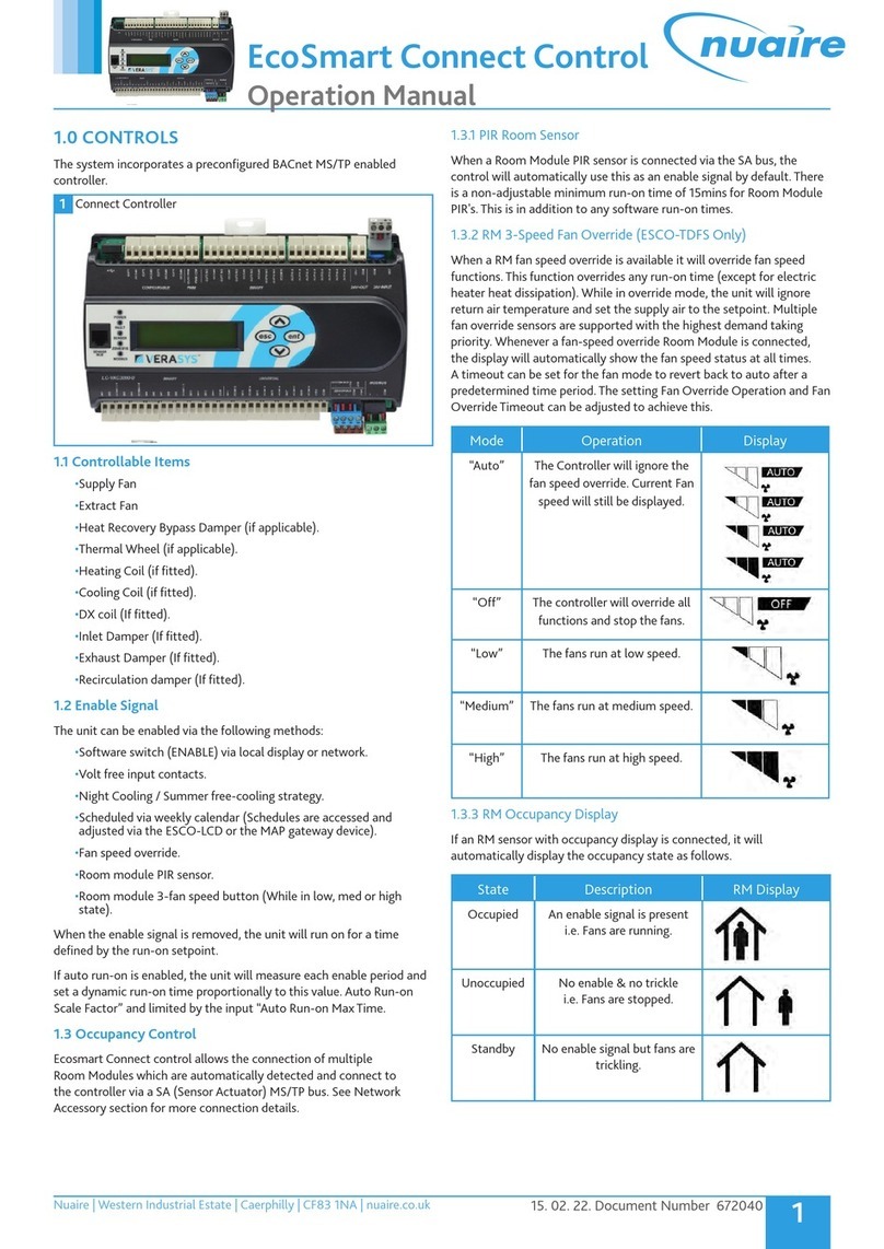
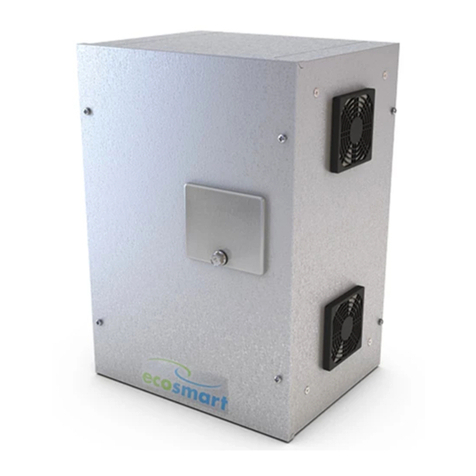
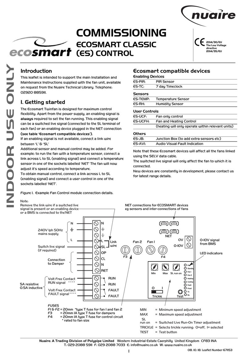
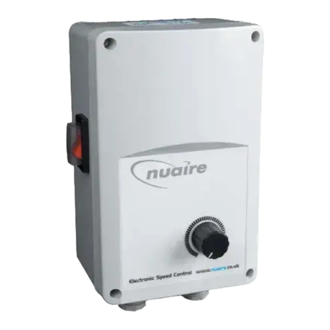
NuAire Ecosmart User manual

1
15. 02. 22. Document Number 671868
Nuaire | Western Industrial Estate | Caerphilly | CF83 1NA |nuaire.co.uk
EcoSmart Connect Control
Quick Controls Guide
1.0 INTRODUCTION
This guide provides basic set up procedure to allow control
commissioning of Nuaire’s Ecosmart Connect control software and
should be read in conjunction with the relevant unit's EcoSmart
installation maintenance manual.
Before commissioning the unit, ensure that all equipment has been
assembled in accordance with the installation procedures detailed in
the unit installation and maintenance manual.
2.0 BASIC COMMISSIONING
The Ecosmart Connect system can only be commissioned by modifying
the controller BACnet object values (in software). This can be done
by connecting to the controller across the network using any BACnet
compatible software.
If a BACnet compatible network is not available, an ESCO-LCD is
required to commission the system. The ESCO-LCD can be permanently
connected on the FC bus (with a separate power supply), or a special
RJ11 connection cable (ESCO-LCD-3M) is supplied for connection
directly to the controller (self-powered). All values will be retained by
the controller once the LCD is disconnected.
2.1 Priority and writing of values
The ESCO-LCD can browse all devices and objects on the network. By
default, it writes variables (BV, AV, MSV) at level 16 and outputs (BO,
AO) at level 8. No BACnet device can write inputs (BI, AI). It is highly
recommended that the write levels are left at the default settings of 16
for Adjust Priority and 8 for Override Priority.
It is not recommended to change or write to any of the outputs
(BO/AO) directly as doing so may cause undesirable results and
override the software permanently. If overridden ensure all values
are relinquished correctly.
2.2 Relinquishing
The ESCO-LCD allows the relinquishing of values by selected an empty
value for analogue values or the ‘---‘value for discrete values. Setting an
analogue value to “0” does not relinquish the command. The relinquish
command will only apply to the priority level set in the settings.
2.3 Navigation of ESCO-LCD
To gain access to the controllers set points via the ESCO-LCD please
select the network page in the top right hand corner of the controller
shown below. Once access is gained select the correct unit by checking
the MAC address. The mac address can be checked via the dip switches
on the front of the connect control (e.g. if 4 and 1 are selected, the mac
address equals 5).
1 ESCO-LCD Menu Screen
Settings
Favourites Target
Network
Cancel – Quit and moves
to the previous section
Home – Shortcut to the
configured Home Page
Back – Moves to the
previous page in the same
section
Forward – Moves to the
next page in the same
section
Enter – Applies changes
2 ESCO-LCD Navigation Buttons
TL-BRTRP-0 0 1
Nuaire BPS ESC 4 0909501
Nuaire BPS ESC 5 0909502
MAC Address
BACnet
Device
ID
3 ESCO-LCD Network Screen
3.0 ENABLING THE UNIT
The unit can be enabled via the following methods:
•Software switch (ENABLE) via local display or network.
•Volt free input contacts.
•Night Cooling / Summer free-cooling strategy.
•Scheduled via weekly calendar (Schedules are accessed and
adjusted via the ESCO-LCD or the MAP gateway device).
•Fan speed override.
•Room module PIR sensor.
•Room module 3-fan speed button (While in low, med or high
state).
When the enable signal is removed, the unit will run on for a time
defined by the run-on setpoint.
If auto run-on is enabled, the unit will measure each enable period and
set a dynamic run-on time proportionally to this value. Auto Run-on
Scale Factor” and limited by the input “Auto Run-on Max Time.
LCD
Browser
Page
BACnet
Object Description Point
Type
Instance
Number
Default
Value Range
2 Unit
Enable
Enable the
Unit
MSV 28512 Off Off / On
2
15. 02. 22. Document Number 671868
Nuaire | Western Industrial Estate | Caerphilly | CF83 1NA |nuaire.co.uk
EcoSmart Connect
Quick Controls Guide
3.1 Setting the Minimum and Maximum Airflows
To set the minimum and maximum fan speeds configure the following
set points:
•Extract fan minimum speed located on page number 29 of the
LCD browser or object ID 28631.
•Extract fan maximum speed located on page number 29 of the
LCD browser or object ID 28632.
•Supply fan minimum speed is located on page number 35 of the
LCD browser or object ID 28671.
•Supply fan maximum speed is located on page number 35 of the
LCD browser or object ID 28672.
LCD
Browser
Page
BACnet
Object Description Point
Type
Instance
Number
Default
Value Range
29
Extract
Fan Max
Demand
Extract Fan
Maximum
Demand
AV 28631 100 0-100
29
Extract
Fan Min
Demand
Extract Fan
Minimum
Demand
AV 28632 20 0-100
35
Supply
Fan Max
Demand
Individual Fan
Maximum
Demand
AV 28671 100 0-100
35
Supply
Fan Min
Demand
Supply Fan
Minimum
Demand
AV 28672 20 0-100
3.1.1 Fan Commissioning
To simulate the maximum speed and check air volumes the fan boost
will have to be enabled. The fan boost is located on page number 11,
object ID 28635. Please ensure this is disabled after commissioning.
3.1.2 Fan Boost
11 Fan Boost Enable Fan Boost MSV 28635 Off Off / On
3.2 Setting Trickle Operation
Enabling the trickle set point will run the fan at minimum speed
when there is no enable signal present. To enable trickle configure the
following set point.
•Trickle mode is located on page number 14 if the LCD browser or
BACnet object ID 28675.
3.2.1 Trickle Mode
14 Trickle Mode Trickle Mode
Enabled MSV 28675 Off Off / On
3.3 Setting the Run-on Timer
Once the enable is removed the unit will run on for the time set by the
run on set point.
•Run-on set point is located on page number 9 of the LCD browser
or BACnet object ID 10267.
3.3.1 Run-on Enable
33 Run-on
(Enable)
Run-On
(Enable)
speed
AV 28663 0 0-120
3.4 Setting the Inlet / Outlet Dampers
If inlet or outlet dampers are fitted to the unit as ancillary items, ensure
the following set points are configured:
•The Inlet outlet damper fitted is located on page number 44 of the
LCD browser or object ID 17660.
•The Inlet outlet damper delay is located on page number 12 of the
LCD browser or object ID 10279.
3.4.1 Inlet / Outlet Dampers
10 OA Damper
Interlock IO Damper Fitted MSV 28617 No No / Yes
32 Damper
Delay Damper Delay AV 28646 0 0-120
3.5 Setting Temperature Control
There are two methods of temperature control available with Ecosmart
Connect controls:
•Temp Control Mode is located on page number 10 if the LCD
browser or BACnet object ID 28619.
3.5.1 Temperature Control
10 Control
Type
Temperature Control
Selection - State 0 (Supply
Temp Control / State 1 (Return
Temp Control)
MSV 28619 State
0
State 0
/ State 1
If there is a heater battery or a cooling coil fitted to the unit ensure the
following set points are configured as a minimal requirement to suit the
unit type and site requirements:
•The heating type is located on page number 31 of the LCD browser
or object ID 10206.
•The cooling type Is located on page number 30 of the LCD browser
or object ID 10203.
•Software set point Is located on page number 14 of the LCD
browser or object ID 10309.
•Set point operation is located on page number 33 of the LCD
browser or object ID 10214 (if there are no room sensors installed
it is recommended that this is set to software only).
1 Heating
Type
Selection of Heating
Type - State 0 (None) /
State 1 (LPHW) / State 2
(Electric Heater) / State 3
(3rd Party)
MSV 28510 State 0 State 0 /
State 1 /
State 2 /
State 3
2 Cooling
Type
Selection of Cooling Type
- State 0 (None) / State
1 (Chilled Water) / State
2 (3rd Party) / State 3
(Reverse Cycle DX)
MSV 28511 State 0 State 0 /
State 1 /
State 2 /
State 3
35 Network
Setpoint
Network Temperature
Setpoint
AV 28669 22 12-28
9Setpoint
Operation
Setpoint Input Operation
- State 0 (Last Changed) /
State 1 (Software Only) /
State 2 (Last Changed with
timeout)
MSV 28613 State 0
State 0 /
State 1 /
State 2
3
15. 02. 22. Document Number 671868
Nuaire | Western Industrial Estate | Caerphilly | CF83 1NA |nuaire.co.uk
EcoSmart Connect
Quick Controls Guide
4.0 AFTER SALES ENQUIRIES
For technical assistance or further product information, including spare
parts and replacement components, please contact the After Sales
Department.
Telephone 02920 858 400
aftersales@nuaire.co.uk
Technical or commercial considerations may, from time to time,
make it necessary to alter the design, performance and dimensions
of equipment and the right is reserved to make such changes without
prior notice.
4
15. 02. 22. Document Number 671868
Nuaire | Western Industrial Estate | Caerphilly | CF83 1NA |nuaire.co.uk
EcoSmart Connect
Quick Controls GuideQuick Controls Guide
NOTES

Other manuals for Ecosmart

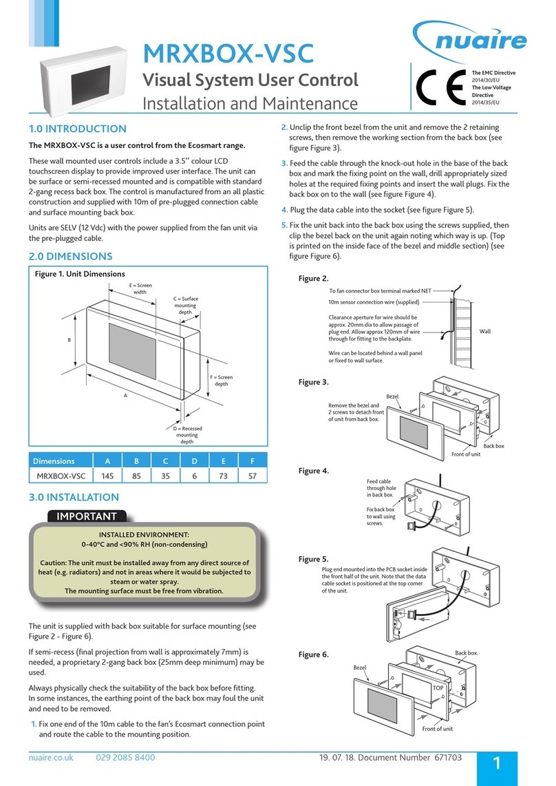
2

Other NuAire Controllers manuals

NuAire Ecosmart User manual

NuAire

NuAire Ecosmart User manual

NuAire Ecosmart ES-ISC Series Instruction Manual

NuAire

NuAire Ecosmart ES-ISC Series Instruction Manual

NuAire DRI-ECO-4S User manual

NuAire

NuAire DRI-ECO-4S User manual

NuAire ECOSMART CLASSIC CONTROL Series Quick start guide

NuAire

NuAire ECOSMART CLASSIC CONTROL Series Quick start guide

NuAire SPCON 1.5A User manual

NuAire

NuAire SPCON 1.5A User manual

NuAire MRXBOX-VSC Instruction Manual

NuAire

NuAire MRXBOX-VSC Instruction Manual

NuAire Ecosmart ES-ISC1.2A User manual

NuAire

NuAire Ecosmart ES-ISC1.2A User manual

Popular Controllers manuals by other brands

DIG LEIT-2 operating instructions

DIG

DIG LEIT-2 operating instructions

BIFFI OLGA-H Use and maintenance manual

BIFFI

BIFFI OLGA-H Use and maintenance manual

BEKA BA658C manual

BEKA

BEKA BA658C manual

Eclipse ES Series instruction manual

Eclipse

Eclipse ES Series instruction manual

Lexicon MC-12HD user guide

Lexicon

Lexicon MC-12HD user guide

Halma ALICAT PCD quick start guide

Halma

Halma ALICAT PCD quick start guide

Omron EJ1 EtherCAT user manual

Omron

Omron EJ1 EtherCAT user manual

HomLiCon LCH5 Operation

HomLiCon

HomLiCon LCH5 Operation

BFC VMC Series instruction manual

BFC

BFC VMC Series instruction manual

AB Quality SMC-3 150-C30NBD Installation

AB Quality

AB Quality SMC-3 150-C30NBD Installation

Danfoss ECL Comfort 301 user guide

Danfoss

Danfoss ECL Comfort 301 user guide

Maxcess Magpowr IPT instruction manual

Maxcess

Maxcess Magpowr IPT instruction manual

Extron electronics VNM Enterprise user guide

Extron electronics

Extron electronics VNM Enterprise user guide

GARDASOFT TR-HT2 Series user manual

GARDASOFT

GARDASOFT TR-HT2 Series user manual

emerald alarms EP-SA-CONT-RF user manual

emerald alarms

emerald alarms EP-SA-CONT-RF user manual

Roger Technology B70/1DCHP Instruction and warnings for the installer

Roger Technology

Roger Technology B70/1DCHP Instruction and warnings for the installer

Toolex 565258 instruction manual

Toolex

Toolex 565258 instruction manual

RoboteQ Dual Channel Digital Motor Controller AX500 user manual

RoboteQ

RoboteQ Dual Channel Digital Motor Controller AX500 user manual

manuals.online logo
manuals.online logoBrands
  • About & Mission
  • Contact us
  • Privacy Policy
  • Terms and Conditions

Copyright 2025 Manuals.Online. All Rights Reserved.