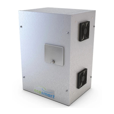
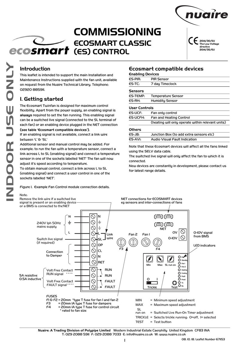
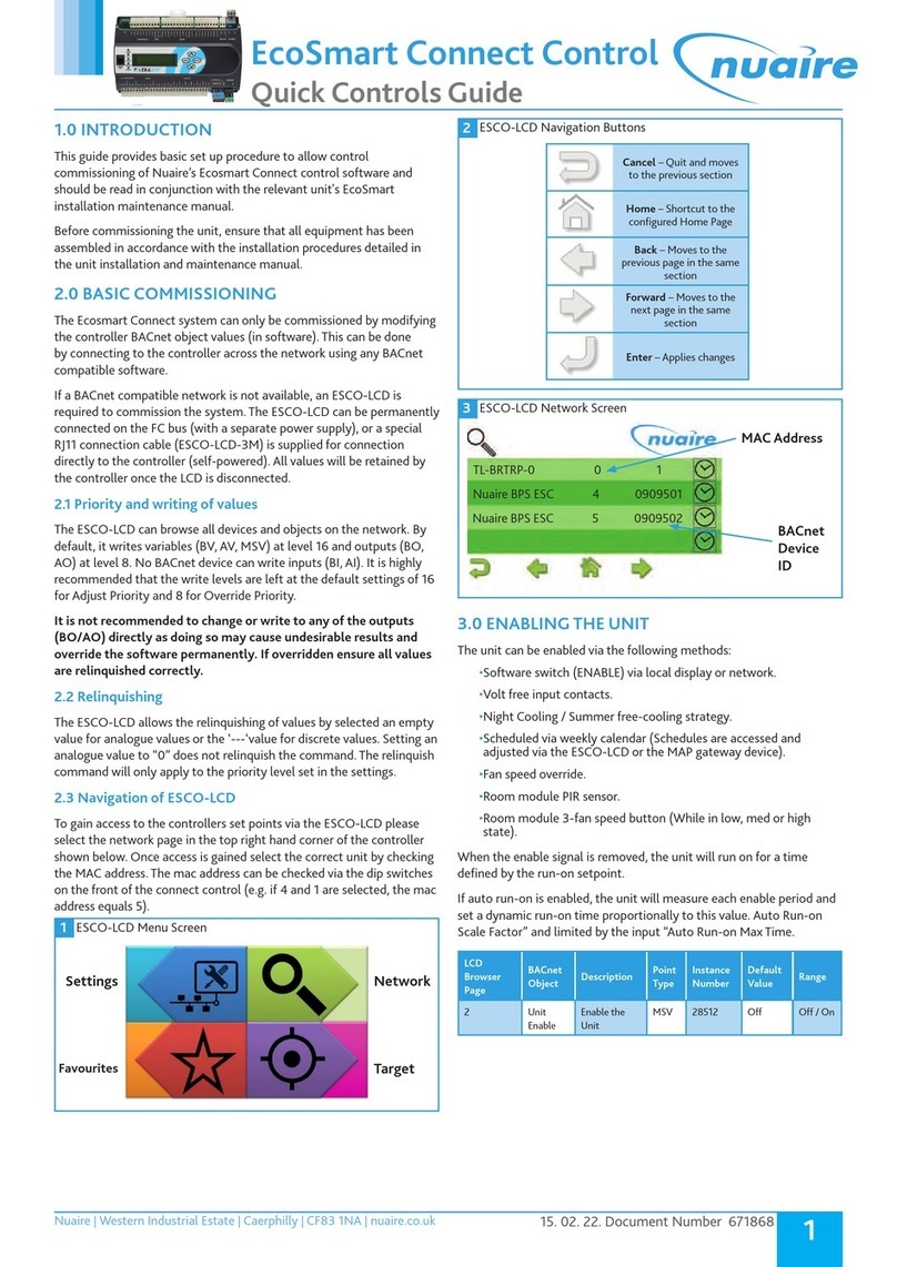
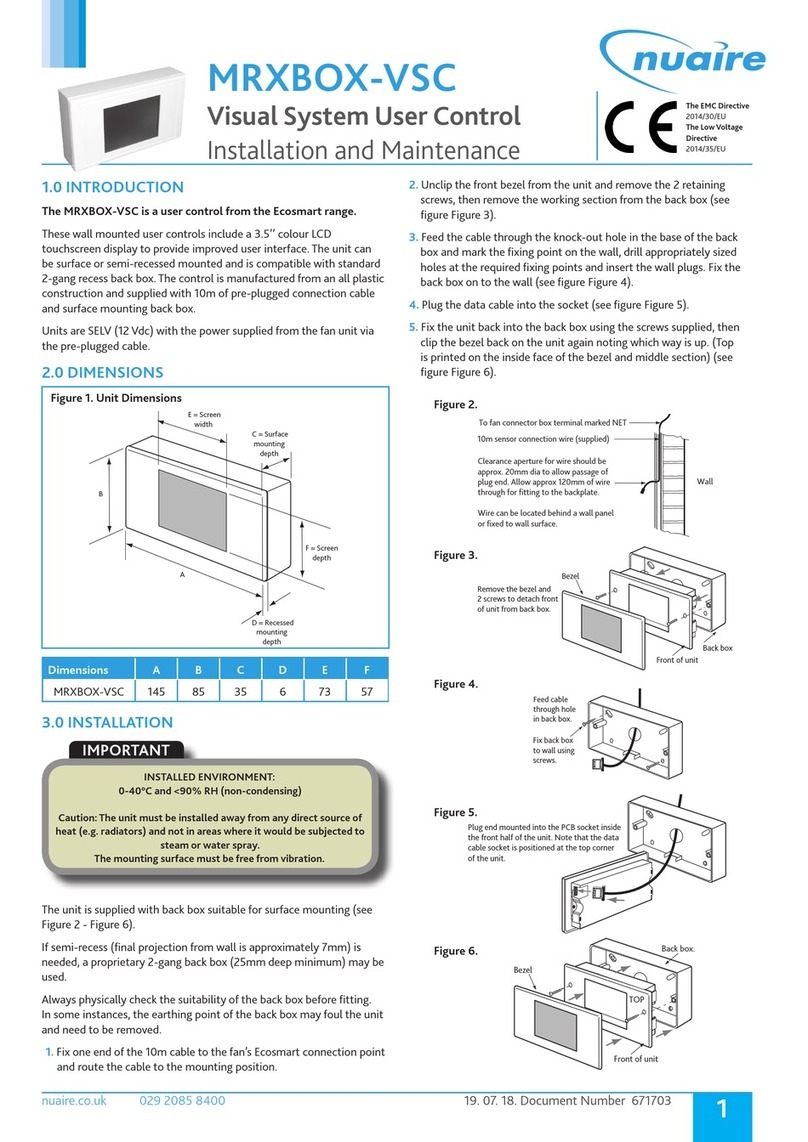
NuAire Ecosmart User manual

1
15. 02. 22. Document Number 672040
Nuaire | Western Industrial Estate | Caerphilly | CF83 1NA | nuaire.co.uk
EcoSmart Connect Control
Operation Manual
1.0 CONTROLS
The system incorporates a preconfigured BACnet MS/TP enabled
controller.
1 Connect Controller
1.1 Controllable Items
•Supply Fan
•Extract Fan
•Heat Recovery Bypass Damper (if applicable).
•Thermal Wheel (if applicable).
•Heating Coil (if fitted).
•Cooling Coil (if fitted).
•DX coil (If fitted).
•Inlet Damper (If fitted).
•Exhaust Damper (If fitted).
•Recirculation damper (If fitted).
1.2 Enable Signal
The unit can be enabled via the following methods:
•Software switch (ENABLE) via local display or network.
•Volt free input contacts.
•Night Cooling / Summer free-cooling strategy.
•Scheduled via weekly calendar (Schedules are accessed and
adjusted via the ESCO-LCD or the MAP gateway device).
•Fan speed override.
•Room module PIR sensor.
•Room module 3-fan speed button (While in low, med or high
state).
When the enable signal is removed, the unit will run on for a time
defined by the run-on setpoint.
If auto run-on is enabled, the unit will measure each enable period and
set a dynamic run-on time proportionally to this value. Auto Run-on
Scale Factor” and limited by the input “Auto Run-on Max Time.
1.3 Occupancy Control
Ecosmart Connect control allows the connection of multiple
Room Modules which are automatically detected and connect to
the controller via a SA (Sensor Actuator) MS/TP bus. See Network
Accessory section for more connection details.
1.3.1 PIR Room Sensor
When a Room Module PIR sensor is connected via the SA bus, the
control will automatically use this as an enable signal by default. There
is a non-adjustable minimum run-on time of 15mins for Room Module
PIR's. This is in addition to any software run-on times.
1.3.2 RM 3-Speed Fan Override (ESCO-TDFS Only)
When a RM fan speed override is available it will override fan speed
functions. This function overrides any run-on time (except for electric
heater heat dissipation). While in override mode, the unit will ignore
return air temperature and set the supply air to the setpoint. Multiple
fan override sensors are supported with the highest demand taking
priority. Whenever a fan-speed override Room Module is connected,
the display will automatically show the fan speed status at all times.
A timeout can be set for the fan mode to revert back to auto after a
predetermined time period. The setting Fan Override Operation and Fan
Override Timeout can be adjusted to achieve this.
Mode Operation Display
“Auto” The Controller will ignore the
fan speed override. Current Fan
speed will still be displayed.
“Off” The controller will override all
functions and stop the fans.
“Low” The fans run at low speed.
“Medium” The fans run at medium speed.
“High” The fans run at high speed.
1.3.3 RM Occupancy Display
If an RM sensor with occupancy display is connected, it will
automatically display the occupancy state as follows.
State Description RM Display
Occupied An enable signal is present
i.e. Fans are running.
Unoccupied No enable & no trickle
i.e. Fans are stopped.
Standby No enable signal but fans are
trickling.

2
15. 02. 22. Document Number 672040
Nuaire | Western Industrial Estate | Caerphilly | CF83 1NA | nuaire.co.uk
BPS H-CO
Installation Manual
1.4 Multiple Sensors
Where multiple sensors are connected the following options are
available.
State Description
Temp Sensor Operation Room module average (Default)
Return Air only
Room Module & Return Air Average
Setpoint Operation Last Value Changed (Default)
Software Setpoint Only
Last Value Changed With Timeout
Humidity Sensor Operation Average (Default)
Max
Ignore
CO2 Sensor Operation Average (Default)
Max
Ignore
Pressure Sensor Operation Average (Default)
Max
Ignore
1.5 Auxiliary Inputs 16 & 17 (0-10V Inputs)
The function of IN16 & IN17 can be set by the network inputs IN16
Function & IN17 Function. The available options are as follows.
Function Description Available Ranges
None The signal is ignored N/A
Fan Speed
Control
A 0-10V input is used as a fan speed
demand.
0V = Min Speed
10V = Max Speed
N/A
EGG
(Ecosmart
Gateway
Gadget)
0-10V from the EGG PCB is controls
used as a fan speed demand. The
optional EGG PCB can be used for
backwards compatibility with some
Ecosmart Classic sensors.
N/A
0-10V
CO2 Sensor
0-10V is scaled as defined by the
network input
“CO2 0-10V Output Range”
0-2,000ppm
0-4,000ppm
0-5,000ppm
0-10,000ppm
0-20,000ppm
0-10V
Temperature
Sensor
0-10V is scaled as defined by the
network input
“Temperature Sensor 0-10V Output
Range”
0 - 40°C
0 - 50°C
0 - 80°C
0 - 90°C
0 - 100°C
0-10V
Pressure
Sensor
0-10V is scaled as defined by the
network input
“Pressure Sensor”
0 - 25 Pa
0 - 50 Pa
0 - 100 Pa
0 - 300 Pa
0 - 500 Pa
0 - 1000 Pa
0 - 1600 Pa
0 - 2500 Pa
0 - 3000 Pa
0-10V
Humidity
Sensor
0-10V is scaled to 0-100%
humidity
0 - 100% only
1.6 Fan Speed Control Input
Once assigned to either input 16 or 17, the 0-10V input is scaled to
0-100% fan speed demand.
1.7 COControl
When a CO2 sensor is assigned to the system and an enable signal
is received, ventilation will increase fans speeds to reduce CO2
concentration. The target CO2 sensor setpoint can be changed as
one of the commissioning setpoints. Room Module CO2 sensors are
detected automatically. 0-10V CO2 sensors need to be assigned to
input 16 or 17.
1.8 Humidity Control
When a humidity sensor is assigned to the system and an enable signals
received, ventilation will increase fans speed to reduce humidity. The
target humidity setpoint can be changed as one of the commissioning
setpoints. Room Module humidity sensors are detected automatically.
0-10V humidity sensors need to be assigned to input 16 or 17.
1.9 Constant Pressure Control
An extract air pressure sensor is fitted to IN16 standard. IN16 is
disabled by default but constant pressure control can be enabled by
setting IN16 function to 0-10v pressure sensor.
When enabled, the unit will increase the fans speeds as required until
the pressure differential between the extract air and atmosphere
reaches the constant pressure setpoint.
The target pressure setpoint can be changed as one of the
commissioning setpoints. Room Module pressure sensors are not
available.
1.10 Dirty Filter Switch
Filter differential pressure switches are fitted as standard. These
monitor the Extract filter, Supply filters. These are connected into input
IN9 & IN10 and will be open circuit on overpressure. The adjustable
range is 0.5 to 4mbar and is set by the default to 2mbar.
1.11 Configurable Mode (Via Switched Live 2)
The switched live 2 input is a configurable input that can be set to
perform a number of functions. The function is set via the network
input Configurable Mode SL2.
These functions will include the following:
•Fan Boost (Default Setting) - This enables Fan Boost Mode
•Heat Boost - The heater function will be enabled. Fan speeds will
be increased where necessary to keep supply temp at the heater
boost setpoint (Default 35°C).
•Extract Setback - When this mode is selected and SL2 is active,
the unit will force the extract fan to run at Extract Setback Speed
(Commissionable setpoint), regardless of all other demands.
Supply fan will operate at the normal speed. If increased demand
is required (e.g. via CO2 or 0-10v IN16/17 some other input) the
supply fan speed will increase but the extract fan speed will not.
This mode can be used when the unit is used in conjunction with a
separate air system.
1.11.1 Fan Boost
When the control receives a boost signal, from either the network input
“Boost” or “Configurable SL2” configured to boost, the fans will run at
their individual boost speeds. Once the signal is removed the fans will
run on for a time defined by the boost run-on setpoint. Any demand in
excess of the boost speed will be ignored (apart from 3 speed override
and purge schedule).
1.11.2 Heat Boost
When the control receives a heat boost signal, from either the network
input “Heat Boost” or “Configurable SL2” configured to “heat boost”,
the heater output will increase to 100%. The fan speed will be increased
as required to reach the heat boost setpoint.

3
15. 02. 22. Document Number 672040
Nuaire | Western Industrial Estate | Caerphilly | CF83 1NA | nuaire.co.uk
BPS H-CO
Installation Manual
1.12 Temperature Control
1.12.1 Supply Temperature Control (Default)
While an enable signal is present, this mode modulates heating, cooling
& heat exchanger bypass dampers with the aim of the supply air
reaching the temperature setpoint. Heating and cooling outputs will
only function if the “Heating Type” or “Cooling Type” network inputs
are set to heating or cooling options.
The heat exchange bypass damper operates by calculating the supply
air temperature based on the return air temperature, the outside air
temperature and the heat exchanger efficiency (e.g. A 13°C outside air
temperature with a 23°C return air temperature will give a supply air
temperature of 20.5°C).
The control then chooses the damper position which requires the
minimal heat/cool tempering in order to achieve the setpoint.
2 Supply Temperature Control - HX Bypass
Room Air Tem p
Supply
Set
Point
Outside Air Temp.
HX
HX
Bypass
Bypass
White areas indicate regions where either heat exchanging or
bypassing will achieve the same supply temperature.
1.12.2 Room Temperature Control
While an enable signal is present, this mode modulates heating,
cooling & heat exchanger bypass dampers with the aim of the room
air reaching the temperature setpoint. Please note that heating and
cooling outputs will only function if the “Heating Type” or “Cooling
Type” network inputs are set to heating or cooling options.
When heating or cooling is required achieve the room setpoint, the
output of the heat/cool loops are split between ventilation demand or
heat/cool demand according to the following graphs. The intermediate
“boost” zone is the area in which a small amount of free heating/
cooling is available. In this zone, heating/cooling is used to boost the
free heating/cooling.
In room temperature control mode, the bypass damper is controlled
according to the following chart. A minimum supply air temperature
limit is included to stop the heat exchanger being bypassed when the
air temp is uncomfortably cold, even though cooling is required. In this
case the heat exchanger will temper the air for comfort. The reverse
applies for the maximum supply air temperature limit.
If the supply air temperature exits the minimum - maximum supply
temperature range, the unit will adjust ventilation, heating or cooling to
compensate.
Room temperature control will only be effective if the heater unit
is sized correctly for the space. If the unit is undersized, heating
from an external source may be required.
Room Air Tem p
Outside Air Temp
Free Heating
Vent Only
Boost Band
Heat Boost Zone
Heating
3 Room Temperature Control - Heating
Room Air Tem p
Cooling
Boost Band
Free Cooling
Vent Only
Outside Air Temp
Cool Boost Zone
4 Room Temperature Control - Cooling
Bypass
Bypass
HX
HX
Deadband
Room Air Tem p
Min Supply O utside Max Supply
Air Temp. Air Temp. Air Temp.
Room
Set
Point
Outside
Air Temp.
5 Room Temperature Control - HX Bypass
1.12.3 Overrides
When the following conditions occur, the system will temporarily exit
“Room Temperature Mode” and enter “Supply Temperature Mode”.
•Trickle Mode with no enable signal (Trickle deadband applies).
•Heat Boost Active
•Fan Boost Active
•Purge Mode Active
•3-Speed override by Room Module

4
15. 02. 22. Document Number 672040
Nuaire | Western Industrial Estate | Caerphilly | CF83 1NA | nuaire.co.uk
BPS H-CO
Installation Manual
1.13 Trickle Mode
When trickle mode is active, the fans will run at their minimum speed
even when there is no enable signal. Heating and cooling will also
function in this mode if available. While in trickle mode, the unit will
function in “Supply Temperature Control Mode” but with a different,
wider deadband, set by the network input Trickle Deadband.
1.14 Frost Protection
Should the internal temperature of the unit fall below a value defined
in the commissioning variables, the control will override all heating/
cooling logic to open the LPHW or CW control valves, if fitted. This is to
allow any protective flow through the heating/cooling coils. The supply
fan will stop and the appropriate frost protection software module will
enter an alarm state. This period will last for a minimum of 5 minutes
by default. The fault relay will also open. Heat and cool demand relays
will operate and the software frost alarm will enter an alarm state.
Frost protection will only function if the Heating Type or Cooling
Type setpoints are set to LPHW or CW.
1.15 Reverse Cycle DX (Optional For BPS Variants)
For units for use with Mitsubishi reverse cycle condenser units, one or
more PACIF012B-E Interface boards are fitted inside the control panel.
The controller interacts with this board in the following ways:
•Digital Output Heat/Cool selection from FAC relay 8. Another
relay is used to split output over multiple boards.
•0-10°c Heat/Cool demand from FAC OUT4 .
•Faults are monitored via iQ4 input 8 (Alarm circuit 2).
When Mitsubishi Reverse Cycle DX is fitted, this is selected in software
by setting the cooling type “Reverse Cycle”. A heating type is not
required unless another heating type is fitted (e.g. LPHW).
Once this is selected cooling and heating demand will share FAC OUT4
and heat/cool is decided on the state of FAC Relay 8 (Energised = Cool
Demand).
For the cases where Reverse Cycle DX and another heating type are
both fitted, the schedule object “Reverse Cycle backup Heating” can be
set to revert to the other heating option at certain times of the day.
Although the controller outputs a variable 0-10v heating/cooling
voltage, the Mitsubishi condenser can only run at 7 discrete levels and
so cannot supply an accurate supply air temperature. For this reason, it
is recommended that the control is set to operate in room temperature
control mode. This will regulate the room air temperature rather than
supply air temperature.
The PAC boards are powered from the BPS control, the only
connections required to the Outdoor condenser are S2 & S3. For the
same reason, SW8-3 must be set to “ON” on the outdoor unit.
The enable run-on time must be set to 3 minutes for reverse cycle
units. This is required to keep the compressor running for at least 3
minutes for each period.
1.16 Night Cooling / Summer Free Cooling
Once enabled in software, this routine can be set to a network time
schedule to cool the fabric of the building at night using only the
external air. This mode only functions if the daytime temperature is
above the setpoint, cooling is possible and if the cooling air is not too
cold.
1.17 Purge Mode
Once enabled in software, this routine can be set to a network time
schedule to provide a period of increased air change throughout a
space. This mode only functions if the inlet air is above a minimum
temperature of 12°C. While purge is in progress, the unit will function
in “Supply Temperature Control Mode” but with a different, wider
deadband, set by the network input “Trickle Deadband”.
1.18 Hibernate Mode
This mode is available for LPHW and CW units where the valves are
required to be driven open in anticipation of a period where the unit is
electrically isolated and inactive. When enabled via the network input
“Hibernate Mode” this will stop the fans and open all LPHW & CW
valves fully. The unit can then be powered down. This mode activation
is reset upon power cycle so when restarted the unit will function as
normal.
This mode is for periods when to building is left dormant and will stop
the coils trapping water and causing a freeze risk. It will be the buildings
responsibility to provide freeze-preventative heating during this time.
This can also be used for a cleaning or flushing cycle.
1.19 Inlet / Outlet Dampers (Optional)
Inlet and outlet dampers are 24vac and controlled by the fan run relay.
When energised it gives a 24vac signal to both I/O dampers to open. A
fan start delay can be imposed to allow the damper time to open. This
is adjustable via display screens or commissioning tools.
When installed, there is the option of connecting the internal damper
close switch to the fault circuit alarm circuit 2 (orange wires).
When IO dampers are fitted the software object “IO Damper Fitted”
must be set to “Yes”. This will cause the software to delay the fans
starting for the IO Damper delay period. It will also ignore faults on
Alarm Circuit 2 if the fans are stopped and the dampers are closed
intentionally. See Internal connection section for physical damper
connections.
1.20 Partial Recirculation Damper (Optional)
If a partial recirculation module is fitted, the recirculation damper will
open / close via OUT8 according to the following strategy.
If the room temperature is more than 5°C (adjustable via recirc-offset
variable) from the setpoint and free-cooling or free-heating is not
available then partially recirculate the air. This aids heating and cooling
elements and avoids thermal loss from the room.
1.21 Alarms
The alarms can be either one of two categories.
1.21.1 Critical Alarm (Latching)
Once in critical alarm state the unit will drive all heating and cooling
outputs to 0V. In the event of fan fail other functions continue as
normal. The critical alarm is latched and requires power cycle or reset
via the “Reset Alarms” variable.
Causes of critical alarm:
•Supply Fan Fail IN1.
•Extract Fan Fail IN2.
•Electric Heater Alarm IN7 (If Fitted).
•Fan Tacho Fail IN8 (If Fitted, this will replace the alarms on IN1 &
IN2).
5
15. 02. 22. Document Number 672040
Nuaire | Western Industrial Estate | Caerphilly | CF83 1NA | nuaire.co.uk
BPS H-CO
Installation Manual
1.21.2 Maintenance Alarm (Non-Latching)
Once in maintenance alarm state the only action taken is de-energising
of the fault relay. Once the trigger is removed, the alarm will reset
automatically.
Causes of maintenance alarm:
•Sensor Failure.
•Low supply temperature, default 8°C. This can be set to stop fans
if required.
•Frost protection routine active, default 4°C (This only runs if water
valves are selected as fitted.
•Excessively high supply temperature reading (This will stop
heating).
•Supply Filter dP fault IN9 (if fitted).
•Extract Filter dP fault IN10 (if fitted).
•Condensate Pump - Alarm IN4 (if fitted).
•IO Damper Alarm - Alarm IN3 (if fitted).
•Thermal Wheel Alarm - Alarm IN11 (if fitted).
All alarms have a hold off period set by the setpoint “Alarm delay”.
1.21.3 Thermal Trip
In case of software failure, as a final resort, the electric heater is
protected by a fail-safe thermal overload switch. This switch disables
the heater controller via a contactor once the temperature reaches
80°C. When this occurs, the critical alarm will latch in software and the
supply contactor will latch in the off position.
Once the unit cools, the contactor will remain latched off until
power cycle.
1.22 Configurable Analogue Output 4 (OUT4)
Relay 8 is a configurable relay output which can be set to the following
functions. It can be set by the multi-state object “RL8 Mode”.
•Cooling Demand (Default Setting)
This option will run the Relay as a cooling command relay. This
output will only function if a cooling type is selected.
•Window Actuator
This option will run a Window Indication routine with a dual CO2
setpoint strategy. Relay 8 will be used to indicate to the end user
whether it is appropriate to open the windows or not. This relay
can be wired to an end user’s signal lamp or other signal. This relay
is SPST so an additional relay is required if a light is required for
each state. A multistate object, ‘Window Mode Status’, exists with
two states, ‘Open’ and ‘Close’.
At external temperatures less than the ‘Window Open Threshold’
(14°C default) the indicator will signal close windows. The ‘CO2 Winter
Target’ will be used as the setpoint (1000ppm default).
At external temperatures greater than the ‘Window Open Threshold’
(14°C default) and CO2 level higher than the ‘CO2 Winter Target’, the
indicator will signal open windows. The ‘CO2 Summer Target’ will be
used as the setpoint (1500ppm default).
If the HX bypass damper is driven to bypass while fans are enabled,
the indicator will signal open windows (HX Bypass due to Condensate
pump failure will not affect windows status).
The ‘Window Mode Status’ will indicate close windows when the unit is
not enabled and at all other times.
1.23 Configurable Analogue Output 4 (OUT4)
OUT4 is a configurable analogue output which can be set to the
following functions via the multi-state object “OUT4 Mode”.
•Cooling Demand (Default Setting)
This will provide a standard 0-10V cooling output. This output will
only function if a cooling type is selected.
•ES Classic BMS
This option will provide a 0-10v ESClassic BMS output based on
ventilation demand. This can then be used in conjunction with
the fan run relay to run multiple slave Classic units from a master
Connect control.
The type of BMS output can be selected by the muti-state object ‘ECS
BMS Thermic Output’.
Auto - The BMS output will switch between heating and cooling
depending on outdoor air temperature.
None - The unit will only supply ‘Vent Only’ voltages.
Heating - The unit will only supply ‘Heating’ voltages.
Cooling - The unit will only supply ‘Cooling’ voltages.
1.23.1 ES Classic BMS Output Table
Function Ventilation Only Cooling Heating
Off / Trickle 0.25V - -
Speed 1 0.5V 0.75V 1V
Speed 2 1.5V 1.75V 2V
Speed 3 2.5V 2.75V 3V
Speed 4 3.5V 3.75V 4V
Speed 5 4.5V 4.75V 5V
Speed 6 5.5V 5.75V 6V
Speed 7 6.5V 6.75V 7V
Speed 8 7.5V 7.75V 8V
Speed 9 8.5V 8.75V 9V
Speed 10 9.5V 9.75V 10V
1.24 Fire Alarm
Once the Fire Alarm object is switched to the Alarm State, all fans,
heating and cooling elements will stop instantly. The fault relay
will de-energise and a fault message will be sent to the ESCO-LCD.
Once the fire alarm status is released, the units will continue running
automatically.
1.25 BACnet Overview
BACnet is a data communication protocol for Building Automation and
Control Networks. It allows compatibility between devices of different
manufacturers. In BACnet, any device on the network can browse the
network and discover devices.
1.26 Writing Values
It is best practice to only write to AV, BV & MSV (Analogue Variables,
Binary Variables, and Multistate Variables). When writing to these, it is
best to write at priority level 16.

6
15. 02. 22. Document Number 672040
Nuaire | Western Industrial Estate | Caerphilly | CF83 1NA | nuaire.co.uk
BPS H-CO
Installation Manual
1.27 Typical Basic Commissioning
•Set the analogue variables “Extract Fan Min Speed”, “Supply Fan
Min Speed”, “Extract Fan Max Speed” and “Supply Fan Max Speed”
during commissioning.
•If flow measurements are required enable the unit using the
“Enable” MSV and boost the unit using the “Fan Boost” MSV.
1.28 Typical Basic Operation
•Enable the unit using the MSV “Enable” object. The fan runs at min
speed.
•Increase the fan speeds using the AV “Fan Speed Demand” 0-100%
(0% = Min Commissioned Speed, 100%= Max Commissioned
Speed).
•Adjust setpoint using the AV “Software Setpoint”.
1.29 Writing Directly To Outputs
•It is not recommended to write directly to outputs since the
internal logic of the control will be bypassed and some features
will not function. The unit may also start without an enable signal.
•However, if this is required for test purposes (or otherwise),
priority level 8 must be used.
•The internal control logic writes at priority level 16 so any data
written to the outputs at this level is at risk of being overwritten.
•These values must be relinquished or nulled once used, otherwise
the outputs will be locked at that value, even if the value is “0”.
1.30 Priority Array Storage
•Priority levels 8 & 16 are stored in the controller following a power
cycle. All other levels are reset to null.
•Level 16 is not to be used for controller outputs since it will be
overridden by the internal logic during operation.
1.31 Devices
A BACnet network can consist of several "device objects". Each device
is given a unique "Device Instance Number". A typical example of a
device is a controller or BACnet compatible LCD. EcoSmart Connect
controllers are assigned a random device instance number at the
factory and do not need to be changed. The instance number range is
1 - 4,194,303 (222). EcoSmart Connect controllers use a MSTP network
for communication and are assigned a default MSTP address of 4.
The MSTP address must not be confused with the Device Instance
Number. Most network browsers can identify a device by the Device
Instance Number or the MSTP address.
1.32 Objects
In BACnet, information is stored within devices as several ‘virtual’
objects. Some examples of these are Fresh Air Temperature, Extract Fan
Speed, CO2 Target, etc. Each object has several properties but the most
important are shown in the table below. The maximum number of
objects in a device is 4,194,303 (222) of each type.
Object Name The name of the object. E.g. Setpoint
Object Instance
Number
A unique number which represents the object within
the device. E.g. 12544
Object Type The type of object. E.g. Analogue Variable (AV)
Description A short description of the object. E.g. The room
setpoint
Present Value The current value of the object. E.g. 20
Units The units of the present value. E.g. °C
1.33 Object Types
A list of some typical object types is shown below.
AI Analogue
Input
An analogue object which is a physical input to a device.
AO Analogue
Output
An analogue object which is a physical output from a
device.
AV Analogue
Variable
An analogue object which exists within a device.
BI Binary
Input
A true/false object which is a physical input to a device.
BO Binary
Ouput
A true/false object which is a physical output from a
device.
BV Binary
Variable
A true/false object which exists within a device.
MSV Multi-
State
Variable
This is an enumerated object which can have a number
of states, each represented by a number. This is similar
to a dropdown menu in windows forms. The State_Text
property is an array containing the text for each value.
Some browsers may not be able to read the text values
so both are provided in this manual. E.g. 1=Off, 2=Low,
3=High, 4=Auto
SCH Schedule
Object
This is a special object with the ability to have a
changing value depending on the time of date or day of
the week.

7
15. 02. 22. Document Number 672040
Nuaire | Western Industrial Estate | Caerphilly | CF83 1NA | nuaire.co.uk
BPS H-CO
Installation Manual
1.34 Writing Of Values (Priority Array)
Any device on the BACnet network can write values to other device
objects. To resolve conflicts, BACnet uses a 16-position priority array to
work out who gets priority. Any request it change the present value is
stored in the priority array at the priority level of the received request.
The object then chooses the highest priority value to become the
present value. Examples of priority array decision making are shown
below.
Case 1
Priority 1 null
Priority 2 null
Priority 3 null
Priority 4 null
Priority 5 null
Priority 6 null
Priority 7 null
Priority 8 null
Priority 9 null
Priority 10 null
Priority 11 null
Priority 12 null
Priority 13 null
Priority 14 null
Priority 15 null
Priority 16 null
Relinquish
Default
0
Present
Value 0
Case 2
Priority 1 null
Priority 2 null
Priority 3 null
Priority 4 null
Priority 5 null
Priority 6 null
Priority 7 null
Priority 8 null
Priority 9 null
Priority 10 null
Priority 11 null
Priority 12 null
Priority 13 null
Priority 14 null
Priority 15 null
Priority 16 5
Relinquish
Default
0
Present
Value 5
Case 3
Priority 1 null
Priority 2 null
Priority 3 null
Priority 4 null
Priority 5 null
Priority 6 null
Priority 7 null
Priority 8 null
Priority 9 7
Priority 10 null
Priority 11 null
Priority 12 null
Priority 13 null
Priority 14 null
Priority 15 null
Priority 16 5
Relinquish
Default
0
Present
Value 7
Case 4
Priority 1 null
Priority 2 null
Priority 3 null
Priority 4 null
Priority 5 null
Priority 6 null
Priority 7 null
Priority 8 null
Priority 9 7
Priority 10 null
Priority 11 null
Priority 12 null
Priority 13 null
Priority 14 null
Priority 15 null
Priority 16 0
Relinquish
Default
0
Present
Value 7
Case 4
Priority 1 null
Priority 2 null
Priority 3 null
Priority 4 null
Priority 5 null
Priority 6 null
Priority 7 null
Priority 8 null
Priority 9 null
Priority 10 null
Priority 11 null
Priority 12 null
Priority 13 null
Priority 14 null
Priority 15 null
Priority 16 0
Relinquish
Default
0
Present
Value 0
•Case 1 - The object looks down the list until it gets to the first
non-null value. In this case, all priority levels are empty so the
(relinquish) default value of 0 is used as the present value.
•Case 2 - Priority 16 is now 5 so the present value becomes 5.
•Case 3 - Priority 9 is now 7. Priority 9 overrules priority 16 so the
present value becomes 7. Note that priority 16 is still calling for 5
but it is being ignored.
•Case 4 - Priority 16 is changed to 0 but this has no effect on the
present value. It is still at 7 because of priority 9.
•Case 5 - Priority 9 is relinquished back to null. This allows priority
16 to take priority again and the present value becomes 0.
The priority array is stored inside the device itself. This means that an
external device can write to a priority position and the value will stay
there even if the device is disconnected.
AI and BI object types are read only and therefore do not have a priority
array.
AO & BO values are typically changed by the strategy at priority level
16. Any override must occur above this level and is not recommend. Be
sure to relinquish all overrides once finished to minimise confusion and
undesirable operation.
AV, BV & MSV values are generally not changed by the strategy so an
external command at priority level 16 is sufficient to change the value
permanently.
The following table shows the standard use of the priority array.
Priority Application
1Manual Life Safety
2Automatic Life Safety
3 Available
4 Available
5Criticial Equipment Control
6Minimum On/Off
7 Available
8Manual Operator
9 Available
10 Available
11 Available
12 Available
13 Available
14 Available
15 Available
16 Available
1.35 Inter-Networking
Inter-networking is used to connect two BACnet networks operating on
different physical mediums (e.g. MSTP & IP). This is possible because no
matter the physical medium, BACnet messages are always the same.
A router can be fitted to the network to translate BACnet between
different physical media.
1.35.1 Example BACnet Network
6 Example BACnet Network
This is a typical example of a BACnet
network.
Not all objecs or properties are shown
for clarity.
Controller
(MSTP address 4)
Device Properties
Object Name: Office 1 Controller
Object Instance: 12222
Description: Office 1 Controller
Location: Office 1
Controller
(MSTP address 5)
Device Properties
Object Name: Office 2 Controller
Object Instance: 12226 Description:
Office 2 Controller
Location: Office 2
Object Properties
Object Name: Room
Air Temp
Object Instance: 10008
Object Type: AI
Present Value: 20.2
Units: °C
Object Properties
Object Name: Humidity
Object Instance: 10104
Object Type: AI
Present Value: 56
Units: Percent
Object Properties
Object Name: Alarm
Object Instance: 17013
Object Type: MSV
Present Value: Normal
State Text: Normal, Alarm
Object Properties
Object Name: Fan Output
Object Instance: 10185
Object Type: AO
Present Value: 0
State Text: Volts
Object Properties
Object Name: Enable
Object Instance: 10288
Object Type: MSV
Present Value: On
State Text: Off, On
Object Properties
Object Name:
Humidity Setpoint
Object Instance: 10104
Object Type: AV
Present Value: 60
State Text: Percent
Object Properties
Object Name: Fan Output
Object Instance: 10182
Object Type: AO
Present Value: 2.8
State Text: Volts
MSTP Connection
Device
Object
Device
Object
Object
Object Object
Object
Object
Object Object

8
15. 02. 22. Document Number 672040
Nuaire | Western Industrial Estate | Caerphilly | CF83 1NA | nuaire.co.uk
BPS H-CO
Installation Manual
1.36 BACnet Object List (By Category)
LCD Page
Number
Object Name Description Point
Type
Instance
Number
Default
Value
Range
1 Baud Rate Baud rate MSV 28508 Auto Auto / 1200 / 9600
/ 19200 / 38400 /
76800
1Unit Selection Unit Type - State 0 (XBC) / State 1 (BPS) /
State 2 (BOXER)
MSV 28509 State 0 State 0 / State 1 /
State 2
1Heating Type Selection of Heating Type - State 0 (None) /
State 1 (LPHW) / State 2 (Electric Heater) /
State 3 (3rd Party)
MSV 28510 State 0 State 0 / State 1 /
State 2 / State 3
2Cooling Type Selection of Cooling Type - State 0 (None) /
State 1 (Chilled Water) / State 2 (3rd Party) /
State 3 (Reverse Cycle DX)
MSV 28511 State 0 State 0 / State 1 /
State 2 / State 3
2 Unit Enable Enable the Unit MSV 28512 Off Off / On
2Unit Fault Status Fault Relay (Output OUT9) MSV 28539 Normal Alarm / Normal / Hold
2RM199 Status Status of Network Sensor 1 MSV 28540 FALSE False / True / Hold
3Alarm Circuit 1 Alarm Circuit 1 MSV 28523 Normal Alarm / Normal / Hold
3Alarm Circuit 2 Alarm Circuit 2 MSV 28524 Normal Alarm / Normal / Hold
3 SL Input SL Enable (Input IN5) MSV 28525 Off Off / On / Hold
3 Cooling Demand Cooling Demand Status MSV 28538 Off Off / On / Hold
4 SL2 Input SL2 Enable (Input IN6) MSV 28526 Off Off / On / Hold
4 Bypass Damper Bypass damper Status (Output OUT6) MSV 28535 Inactive Inactive / Active / Hold
4 Heat Demand Heat / Recirc Demand (Output OUT8) MSV 28536 Off Off / On / Hold
4Fan Command Fan Enable Command (Output OUT10) MSV 28537 On Off / On / Hold
5RM200 Status Status of Network Sensor 2 MSV 28547 FALSE False / True / Hold
5RM201 Status Status of Network Sensor 3 MSV 28554 FALSE False / True / Hold
5RM202 Status Status of Network Sensor 4 MSV 28561 FALSE False / True / Hold
5RM203 Status Status of Network Sensor 5 MSV 28568 FALSE False / True / Hold
6RM204 Status Status of Network Sensor 6 MSV 28575 FALSE False / True / Hold
6RM205 Status Status of Network Sensor 7 MSV 28582 FALSE False / True / Hold
6 0-10v Press Range for
IN16 & IN17
0-10v Pressure Range Select for IN16 & IN17
- State 0 (0-25) / State 1 (0-50) / State 2
(0-100) / State 3 (0-300) / State 4 (0-500) /
State 5 (0-1000) / State 6 (0-1600) / State 7
(0-2500) / State 8 (0-3000)
MSV 28599 State 0 State 0 / State 1 /
State 2 / State 3 /
State 4 / State 5 /
State 6 / State 7 /
State 8
60-10v CO2 Range for
IN16 & IN17
0-10v CO2 Range Select for IN16 & IN17 -
State 0 (0-2000) / State 1 (0-4000) / State
2 (0-5000) / State 3 (0-10000) / State 4
(0-20000)
MSV 28600 State 0 State 0 / State 1 /
State 2 / State 3 /
State 4
6IN16 is Temperature Is IN16 setup as = MSV 28601 FALSE False / True / Hold
6 IN16 is Humidity Is IN16 setup as = MSV 28602 FALSE False / True / Hold
6IN16 is CO2 Is IN16 setup as = MSV 28603 FALSE False / True / Hold
6 IN16 is Pressure Is IN16 setup as = MSV 28604 FALSE False / True / Hold
6IN17 is Temperature Is IN17 setup as = MSV 28605 FALSE False / True / Hold
6 IN17 is Humidity Is IN17 setup as = MSV 28606 FALSE False / True / Hold
6IN17 is CO2 Is IN17 setup as = MSV 28607 FALSE False / True / Hold
6 IN17 is Pressure Is IN17 setup as = MSV 28608 FALSE False / True / Hold
6RM199 Fan Speed
Request
RM199 Fan Speed AV 28545 Current 0, Auto / 1, Off / 2,
Low / 3, Medium / 4,
High

9
15. 02. 22. Document Number 672040
Nuaire | Western Industrial Estate | Caerphilly | CF83 1NA | nuaire.co.uk
BPS H-CO
Installation Manual
LCD Page
Number
Object Name Description Point
Type
Instance
Number
Default
Value
Range
6RM199 Occupancy RM199 Occupancy AV 28546 Current 0, Occupied / 1,
Unoccupied / 2, Bypass
/ 3, Standby
6RM200 Fan Speed
Request
RM200 Fan Speed AV 28552 Current 0, Auto / 1, Off / 2,
Low / 3, Medium / 4,
High
6RM202 CO2 AI RM202 CO2 Sensor Analogue Input AV 28564 Current 0 - 2000
6RM202 Sensor Setpoint RM202 Setpoint AV 28565 Current 0-100
6RM203 CO2 AI RM203 CO2 Sensor Analogue Input AV 28571 Current 0 - 2000
6RM205 Temp AI RM205 Temperature Sensor Analogue Input AV 28583 Current 0-40
6RM205 Humidity AI RM205 Humidity Sensor Analogue Input AV 28584 Current 0 -100
6RM206 Temp AI RM206 Temperature Sensor Analogue Input AV 28590 Current 0-40
7RM206 Status Status of Network Sensor 8 MSV 28589 FALSE False / True / Hold
7 IN16 Function IN16 Function Input - State 0 (None) / State
1 (N/A) / State 2 (N/A) / State 3 (0-10v CO2
Sensor) / State 4 (0-10v Temp Sensor) / State
5 (0-10v Hum Sensor) / State 6 (0-10v Press
Sensor)
MSV 28596 State 0 State 0 / State 1 /
State 2 / State 3 /
State 4 / State 5 /
State 6
7 IN17 Function IN17 Function Input - State 0 (None) / State
1 (FS Control) / State 2 (0-10v BMS) / State
3 (0-10v CO2 Sensor) / State 4 (0-10v Temp
Sensor) / State 5 (0-10v Hum Sensor) / State
6 (0-10v Press Sensor)
MSV 28597 State 0 State 0 / State 1 /
State 2 / State 3 /
State 4 / State 5 /
State 6
70-10v Temp Range for
IN16 & IN17
0-10v Temp Range Select for IN16 & IN17 MSV 28598 State 0 State 0 / State 1 /
State 2 / State 3 /
State 4
7RM200 Occupancy RM200 Occupancy AV 28553 0, Occupied / 1,
Unoccupied / 2, Bypass
/ 3, Standby
7RM203 Sensor Setpoint RM203 Setpoint AV 28572 0-100
7RM206 Humidity AI RM206 Humidity Sensor Analogue Input AV 28591 0 -100
8Temp Sensor Operation Temperature Sensor Operation - State 0 (RM
Average) / State 1 (Return Air Only) / State 2
(RM & Return Air Average)
MSV 28609 State 0 State 0 / State 1 /
State 2
8Humidity Sensor
Operation
Humidity Sensor Operation - State 0
(Average) / State 1 (Minimum) / State 2
(Ignore)
MSV 28610 State 0 State 0 / State 1 /
State 2
8CO2 Sensor Operation CO2 Sensor Operation - State 0 (Average) /
State 1 (Minimum) / State 2 (Ignore)
MSV 28611 State 0 State 0 / State 1 /
State 2
8Pressure Sensor
Operation
Pressure Sensor Operation - State 0
(Average) / State 1 (Minimum) / State 2
(Ignore)
MSV 28612 State 0 State 0 / State 1 /
State 2
9Setpoint Operation Setpoint Input Operation - State 0 (Last
Changed) / State 1 (Software Only) / State 2
(Last Changed with timeout)
MSV 28613 State 0 State 0 / State 1 /
State 2
9Supp Heat Output BMS Configuration Input - State 0 (Auto) /
State 1 (None) / State 2 (Heating) / State 3
(Cooling)
MSV 28614 State 0 State 0 / State 1 /
State 2 / State 3
9Fan Speed Override
Control
Fan Speed Override Operation - State 0
(Override has Priority) / State 1 (Revert to
Auto after Timeout)
MSV 28615 State 0 State 0 / State 1
9Occ Sensor Enable Occupancy Sensor Enabled MSV 28616 No No / Yes
10 OA Damper Interlock IO Damper Fitted MSV 28617 No No / Yes

10
15. 02. 22. Document Number 672040
Nuaire | Western Industrial Estate | Caerphilly | CF83 1NA | nuaire.co.uk
BPS H-CO
Installation Manual
LCD Page
Number
Object Name Description Point
Type
Instance
Number
Default
Value
Range
10 Tacho Board Fitted Tacho Board Fitted MSV 28618 No No / Yes
10 Control Type Temperature Control Selection - State 0
(Supply Temp Control / State 1 (Return Temp
Control)
MSV 28619 State 0 State 0 / State 1
10 Fan Config Fan Configuration for Boxer Units - State 0
(Supply Only) / State 1 (Extract Only) / State
2 (Both)
MSV 28620 State 2 State 0 / State 1 /
State 2
11 Fan Off Delay Auto Run-On MSV 28624 Off Off / On
11 Damper Override LV Manual Damper override - State 0 (Auto) /
State 1 (HX) / State 2 (Bypass)
MSV 28626 State 0 State 0 / State 1 /
State 2
11 Fan Boost Enable Fan Boost MSV 28635 Off Off / On
11 Fire Alarm Fire Alarm Network Input MSV 28638 Normal Normal / Alarm
12 Hibernate Mode Hibernate Mode MSV 28643 Off Off / On
12 Low Temp Alarm Action Low Supply Temp Action - State 0 (Alarm
Only) / State 1 (Alarm & Stop Fans)
MSV 28647 State 0 State 0 / State 1
12 NFC Sch Night Cooling Sampling Schedule MSV 28651 Off Off / On
12 NFC Sch Enable Night Cooling Schedule Enable MSV 28652 Off Off / On
13 Cooling Output Type OUT4 Mode Selection - State 0 (Cooling
Demand) / State 1 (ESClassic BMS)
MSV 28653 State 0 State 0 / State 1
13 Purge Purge Enable MSV 28655 Off Off / On
13 Purge Command Purge Schedule MSV 28656 Off Off / On
13 SL2 Mode Switch Live 2 Mode - State 0 (None) / State 1
(Fan Boost) / State 2 (Heating Boost) / State
3 (Extract Setback)
MSV 28668 State 0 State 0 / State 1 /
State 2 / State 3
13 EF Setback from SF Setback Speed of Extract from Supply for
Positive Pressure
MSV 28633 Off Off / On
14 PID Tuning Mode Tuning Reset for PID Loops MSV 28674 FALSE False / True / Hold
14 Trickle Mode Trickle Mode Enabled MSV 28675 Off Off / On
14 Local Schedule Unit Enable (Via Schedule) MSV 28680 On Off / On
14 Alarm Reset Reset the Alarms MSV 28681 FALSE False / True / Hold
14 Heat Boost Enable heater Function MSV 28641 Off Off / On
15 Fan Active Fan Run-on Active MSV 28682 FALSE False / True / Hold
15 Occupancy Status Occupancy mode wo Runon MSV 28683 0 0, Occupied / 1,
Unoccupied / 2, Bypass
/ 3, Standby
15 Fan to Damper Delay IO Damper Delay Active MSV 28684 FALSE False / True / Hold
15 Active Critical Alarms Critical Alarm MSV 28685 Normal Normal / Alarm
15 Re-circ Override Re-circulation Override - State 0 (Auto) /
State 1 (Open) / State 2 (Close)
MSV 28677 State 0 State 0 / State 1 /
State 2
16 Maintenance Alarm Maintenance Alarm MSV 28686 Normal Normal / Alarm
16 Condensate Alarm Condensate Alarm MSV 28688 Normal Normal / Alarm
16 Dirty Pre-filter alarm Dirty Pre-filter alarm MSV 28689 Normal Normal / Alarm
16 Supply Fan Alarm Supply Fan Alarm MSV 28692 Normal Normal / Alarm
17 Return Air dirty filter
alarm
Extract Filter dirty alarm MSV 28690 Normal Normal / Alarm
17 Return Fan Alarm Return Fan Alarm MSV 28693 Normal Normal / Alarm
18 Thermal Wheel Alarm Thermal Wheel Alarm MSV 28687 Normal Normal / Alarm
18 Tacho Alarm Tacho Alarm MSV 28691 Normal Normal / Alarm

11
15. 02. 22. Document Number 672040
Nuaire | Western Industrial Estate | Caerphilly | CF83 1NA | nuaire.co.uk
BPS H-CO
Installation Manual
LCD Page
Number
Object Name Description Point
Type
Instance
Number
Default
Value
Range
19 MVServiceInactive - -
19 MVServiceActive - -
19 MVServicePriority - -
20 8-1/ Boot - -
20 MVServicePriority - -
20 MVCrticialInactive - -
20 MVCriticalActive - -
21 8-1/ Main - -
21 8-1/ Archive - -
21 8-1/ Static - -
21 8-1/ Dynamic - -
22 8-1/ Flash Memory - -
22 8-1/ Data Model View
Def
- -
22 8-1/ Data Model
Templates
- -
22 8-1/ Backup Parameters - -
22 8-1/ Restore Parameters - -
23 ServiceInactiveEventNTF - -
23 Enable Schedule SCH -
23 Alarm Reset SCH -
24 Critical Inactive Event
NTF
- -
24 Service Priority Inactive
Event NTF
- -
24 Service Priority Inactive
Event NTF
- -
24 Service Active Event NTF - -
25 Fresh Air intake Fresh air Temperature AV 28501 Current 0-100
25 Supply Air Temperature Supply Air temperature AV 28502 Current 0-100
25 Return Air Temperature Return Air Temperature AV 28503 Current 0-100
25 Room Temperature Room Temperature AV 28504 Current 0-100
25 Notification - -
25 Critical Active Event NTF - -
25 Room Temperature
Trend
Used for Trending the Room Temperature TND1 -
25 Room CO2 Trend Used for Trending the Room CO2 TND2 -
26 Address Device MS/TP Address AV 28505 4 4-127
26 Device OID Device Instance Number AV 28506 5
26 Effective Setpoint Current Effective Setpoint AV 28527 0-100
26 Cooling Output Cooling Output AV 28534 0-100
26 Room Humidity Trend Used for Trending the Room Humidity TND3
26 Supply Air Temperature
Trend
Used for Trending the Supply Air Temperature TND5
26 Return Air temperature
Trend
Used for Trending the Extract Air Temperature TND6

12
15. 02. 22. Document Number 672040
Nuaire | Western Industrial Estate | Caerphilly | CF83 1NA | nuaire.co.uk
BPS H-CO
Installation Manual
LCD Page
Number
Object Name Description Point
Type
Instance
Number
Default
Value
Range
26 Setpoint Trend Used for Trending the Temperature Setpoint TND4
27 Effective CO2 Current Effective Room CO2 AV 28528 0-100
27 Effective Humidity Current Effective Room Humidity AV 28529 0-100
27 Effective Pressure Current Effective Room Pressure AV 28530 0-100
27 Supply Fan Speed AO Supply Fan Speed Analogue Output AV 28531 0-10
27 Fresh Air Temperature
Trend
Used for Trending the Fresh Air Temperature TND7
28 Exhaust Fan Speed AO Extract Fan Speed Analogue Output AV 28532 0-10
28 Heating Output Heating Output AV 28533 0-100
28 Frost Protection
Temperature
Minimum Temperature for Frost protection
to start
AV 28640
28 Duct Static Pressure
Setpoint
Pressure Target AV 28654 400 0-1500
28 IN15 CO2 Sensor IN15 CO2 Sensor AV 28513 0-100
28 IN15 Temperature
Sensor
IN15 Temperature Sensor AV 28514 0-100
28 IN15 Humidity Sensor IN15 Humidity Sensor AV 28515 0-100
28 IN15 Pressure Sensor IN15 Pressure Sensor AV 28516 0-100
28 IN16 CO2 Sensor IN16 CO2 Sensor AV 28517 0-100
28 IN16 Temperature
Sensor
IN16 Temperature Sensor AV 28518 0-100
28 IN16 Humidity Sensor IN16 Humidity Sensor AV 28519 0-100
28 IN16 Pressure Sensor IN16 Pressure Sensor AV 28520 0-100
28 IN16 Fan Speed Control IN16 Fan Speed Control AV 28521 0-100
28 IN16 BMS 0-10v IN16 BMS 0-10v AV 28522 0-100
29 CO2 Setpoint In-Room CO2 Setpoint AV 28625 0-200
29 Deadband Temperature Deadband for Supply
temperature control
AV 28627 0-10
29 Fan Override Timeout Time period for Fan Override AV 28636 0-7200
29 Frost Protection Fan off
Delay
Delay Timer for Fan during frost protection AV 28639 0-600
29 Extract Fan Max
Demand
Extract Fan Maximum Demand AV 28631 100 0-100
29 Extract Fan Min Demand Extract Fan Minimum Demand AV 28632 20 0-100
29 Extract Fan Setback
Speed
Set the speed for the Setback AV 28634 30 0-100
29 RM199 Temp AI RM199 Temperature Sensor Analogue Input AV 28541 0-40
29 RM199 Humidity AI RM199 Humidity Sensor Analogue Input AV 28542 0 -100
29 RM201 Temp AI RM201 Temperature Sensor Analogue Input AV 28555 0-40
29 RM201 Humidity AI RM201 Humidity Sensor Analogue Input AV 28556 0 -100
29 RM201 Fan Speed
Request
RM201 Fan Speed AV 28559 0, Auto / 1, Off / 2,
Low / 3, Medium / 4,
High
29 RM201 Occupancy RM201 Occupancy AV 28560 0, Occupied / 1,
Unoccupied / 2, Bypass
/ 3, Standby
29 RM203 Fan Speed
Request
RM203 Fan Speed AV 28573 0, Auto / 1, Off / 2,
Low / 3, Medium / 4,
High

13
15. 02. 22. Document Number 672040
Nuaire | Western Industrial Estate | Caerphilly | CF83 1NA | nuaire.co.uk
BPS H-CO
Installation Manual
LCD Page
Number
Object Name Description Point
Type
Instance
Number
Default
Value
Range
29 RM203 Occupancy RM203 Occupancy AV 28574 0, Occupied / 1,
Unoccupied / 2, Bypass
/ 3, Standby
29 RM204 CO2 AI RM204 CO2 Sensor Analogue Input AV 28578 0 - 2000
29 RM204 Sensor Setpoint RM204 Setpoint AV 28579 0-100
29 RM206 CO2 AI RM206 CO2 Sensor Analogue Input AV 28592 0 - 2000
29 RM206 Sensor Setpoint RM206 Setpoint AV 28593 0-100
30 Alarm Delay A time delay for the alarm signal AV 28621 0-120
30 Auto Run-on Scale
Factor
a multiplier for the run-on timer. AV 28622 0-10
30 BMS 0-10V Input 0-10V Network Fan speed demand, along
with OUT4 output in "ESClassic BMS" mode
AV 28623 0-10
30 Fan Speed Command 0-10V Network Fan Speed Demand AV 28637 0-100
30 Extract Fan Max Voltage Extract Fan Maximum Voltage AV 28628 10 0-10
30 Extract Fan Start Volt Extract Fan Minimum Voltage AV 28629 1 0-10
30 Extract Fan Boost Speed Extract Fan Boost Speed AV 28630 100 0-100
30 RM199 CO2 AI RM199 CO2 Sensor Analogue Input AV 28543 0 - 2000
30 RM199 Sensor Setpoint RM199 Setpoint AV 28544 0-100
30 RM200 Temp AI RM200 Temperature Sensor Analogue Input AV 28548 0-40
30 RM200 Humidity AI RM200 Humidity Sensor Analogue Input AV 28549 0 -100
30 RM201 CO2 AI RM201 CO2 Sensor Analogue Input AV 28557 0 - 2000
30 RM201 Sensor Setpoint RM201 Setpoint AV 28558 0-100
30 RM202 Temp AI RM202 Temperature Sensor Analogue Input AV 28562 0-40
30 RM202 Humidity AI RM202 Humidity Sensor Analogue Input AV 28563 0 -100
30 RM202 Fan Speed
Request
RM202 Fan Speed AV 28566 0, Auto / 1, Off / 2,
Low / 3, Medium / 4,
High
30 RM202 Occupancy RM202 Occupancy AV 28567 0, Occupied / 1,
Unoccupied / 2, Bypass
/ 3, Standby
30 RM204 Temp AI RM204 Temperature Sensor Analogue Input AV 28576 0-40
30 RM204 Humidity AI RM204 Humidity Sensor Analogue Input AV 28577 0 -100
30 RM204 Fan Speed
Request
RM204 Fan Speed AV 28580 0, Auto / 1, Off / 2,
Low / 3, Medium / 4,
High
30 RM204 Occupancy RM204 Occupancy AV 28581 0, Occupied / 1,
Unoccupied / 2, Bypass
/ 3, Standby
30 RM205 CO2 AI RM205 CO2 Sensor Analogue Input AV 28585 0 - 2000
30 RM205 Sensor Setpoint RM205 Setpoint AV 28586 0-100
30 RM206 Fan Speed
Request
RM206 Fan Speed AV 28594 0, Auto / 1, Off / 2,
Low / 3, Medium / 4,
High
30 RM206 Occupancy RM206 Occupancy AV 28595 0, Occupied / 1,
Unoccupied / 2, Bypass
/ 3, Standby
31 SA-T High Limit Supply High Temperature High Limit AV 28644 50 40-60
31 Humidity Setpoint In-room humidity Setpoint AV 28645 50 40-60
31 SA-T Low Limit Supply Low Temperature Low Limit AV 28648 8 5-15

14
15. 02. 22. Document Number 672040
Nuaire | Western Industrial Estate | Caerphilly | CF83 1NA | nuaire.co.uk
BPS H-CO
Installation Manual
LCD Page
Number
Object Name Description Point
Type
Instance
Number
Default
Value
Range
31 Max Auto Run-on Run on Time AV 28649 600 0-1200
31 RM200 CO2 AI RM200 CO2 Sensor Analogue Input AV 28550 0 - 2000
31 RM200 Sensor Setpoint RM200 Setpoint AV 28551 0-100
31 RM203 Temp AI RM203 Temperature Sensor Analogue Input AV 28569 0-40
31 RM203 Humidity AI RM203 Humidity Sensor Analogue Input AV 28570 0 -100
31 RM205 Fan Speed
Request
RM205 Fan Speed AV 28587 0, Auto / 1, Off / 2,
Low / 3, Medium / 4,
High
31 RM205 Occupancy RM205 Occupancy AV 28588 0, Occupied / 1,
Unoccupied / 2, Bypass
/ 3, Standby
32 Damper Delay Damper Delay AV 28646 0 0-120
32 NFC Fan Speed Night Free Cooling Fan Speed AV 28650 60 0-100
32 Purge Fan Speed Purge Fan Speed AV 28657 60 0-100
32 Purge Low SA-T Setpoint Purge Maximum Temperature AV 28658 5 30-21
32 Purge Min Temp Purge Minimum Temperature AV 28659 15 0-30
32 Heat Boost Setpoint Heat Boost Temperature Setpoint AV 28642 35 30-40
33 RTC Max Supply Temp Return Temp Control Maximum Supply Temp AV 28660 35 30-40
33 RTC Min Supply Temp Return Temp Control Minimum Supply Temp AV 28661 12 10-20
33 Run-on (Boost) Run-On (Boost) speed AV 28662 0 0-120
33 Run-on (Enable) Run-On (Enable) speed AV 28663 0 0-120
34 Setpoint Schedule Setpoint Schedule AV 28664 0 12-28
34 Setpoint Timeout Setpoint Timeout AV 28665 0 0-7200
34 Supply Fan Max Volt Supply Temperature Max Voltage AV 28666 10 0-10
34 Supply Fan Start Volt Supply Temperature Start Voltage AV 28667 1 0-100
35 Network Setpoint Network Temperature Setpoint AV 28669 22 12-28
35 Supply Fan Boost Speed Supply Temperature Boost Speed AV 28670 100 0-100
35 Supply Fan Max Demand Supply Temperature Max Demand AV 28671 100 0-100
35 Supply Fan Min Demand Supply Temperature Min Demand AV 28672 20 0-100
36 Trickle Deadband Trickle Temperature Deadband AV 28673 5 0-10
40 Re-circ Offset Re-circulation offset temperature AV 28678 0-100
41 Fan Start Delay (BPS
Only)
For R32 Delay AV 28676 300 0-300
42 Reverse Cycle Backup
Heating
Reverse Cycle Backup Heating MSV 28679 Off Off / On

15
15. 02. 22. Document Number 672040
Nuaire | Western Industrial Estate | Caerphilly | CF83 1NA | nuaire.co.uk
BPS H-CO
Installation Manual
2.0 FC BUS DEVICES
2.1 Networking Connection Example
7 Networking Connection Example
Ethernet IP
MTSP to IP Router
(Sensor Actuator) SA Bus
For best results, use a linear network and switch on the EOL resistors at each end of the FC bus.
(Sensor Actuator) SA Bus
(Field Controller) FC Bus
The FC Bus has a maximum limit of 31 devices

16
15. 02. 22. Document Number 672040
Nuaire | Western Industrial Estate | Caerphilly | CF83 1NA | nuaire.co.uk
BPS H-CO
Installation Manual
2.2 FAC Controller
An FAC controller is used to control the unit. The controller can connect
to the FC bus via the 4 pin FC connection.
8 FAC Controller
2.2.1 MAC Address
The physical MAC address of the FAC adjustable between 4-127
and is set via the DIP switch on the front of the unit. When multiple
controllers are connected on the same FC bus, each controller ‘s MAC
address must be unique.
2.2.2 BACnet Instance Number
The BACnet instance number of the FAC is factory-set to a random
unique value from 0-4,194,304. This ensures that every controller will
have a unique BACnet instance number on any possible network.
2.2.3 End Of Line (EOL) Resistor
When an FAC controller is used as a terminator at the end of a FC
bus line, the EOL resistor dip switch can be switched on for best
performance.
2.2.4 Fault Light Status
•Blink 5Hz - Not all possible room modules are connected. This
is normal.
•Blink 2Hz - Startup in progress
•Off Steady - No Faults
•On Steady - No Software
2.2.5 Current Loop DIP Switches
These should all be set to disabled. Enabling these switches will cause
incorrect sensor values.
2.3 BACnet IP To MS/TP Router (ESCO-IPN)
The BACnet IP to MS/TP Router exchanges information between
networks and allows the controller to communicate on an IP network.
One router is required for each MS/TP network.
9 ESCO-IPN
The BACnet router has a USB 2.0, Type B receptacle which is only used
to obtain power from a computer or USB adapter. A mains adapter
and cable is supplied. The router connects to the FC bus via screwed
terminals.
Address Type Default Address
IP Address 192.168.92.68
Subnet Mask 255.255.255.0 (/24)
A reset switch is available inside a small hole located on the side of the
case. If you press the reset switch with a paper clip (or similar device)
for at least 1 second, the switch resets to the default values of the IP
address, gateway address, and netmask. After you use the reset switch,
you need to reboot the router. The BACnet/IP to MS/TP Router contains
a Web server. You can access the Web server from any Internet-
compatible computer on the local network. To configure the router, you
need a computer with an Ethernet connection, router, and standard
Web browser.
2.4 Interconnection
The FC bus connects via the following MSTP cabling:
ESCO-MSTPC30M - Ecosmart Connect MSTP cable reel 30m
ESCO-MSTPC150M - Ecosmart Connect MSTP cable reel 150m
Suggested Wiring Colouring:
White +
Green -
Black COM
Red Unused
On the SA Bus, the + and - wire are one twisted pair, and the COM and
SA PWR are the second twisted pair of wires. These cannot be used with
RJ12 connections and must be stripped and connected using screwed
terminals. The shield must be earthed at the control panel end only and
be made continuous along the bus length. Room Modules must not be
fitted more than 150metres (cable length) from the controller.
2.5 Touch Screen (ESCO-LCD) Field Advanced Display (FAD)
The ESCO-LCD is a user friendly operator interface featuring BACnet®
communication and a colourful, graphic display with touch-screen
interface. It is powered by 12-24VAC / VDC and connected via the FC
bus.
10 ESCO-LCD

17
15. 02. 22. Document Number 672040
Nuaire | Western Industrial Estate | Caerphilly | CF83 1NA | nuaire.co.uk
BPS H-CO
Installation Manual
2.5.1 ESCO-LCD Navigation
Cancel – Quit and moves
to
the previous section
Home – Shortcut to the
configured Home Page
Back – Moves to the
previous page in the same
section
Forward – Moves to the
next page in the same
section
Enter – Applies changes
Device Name
Device ID
MAC Address
Descriptions
Baud Rate
Max Info Frames
FAD0351
127
127
Field Advanced Display
38400
4
Network Settings
TL-BRTRP-0 0 1
Nuaire BPS ESC 4 0909501
Nuaire BPS ESC 5 0909502
Settings
Favourites
Target
Network
Enable Off MSV 10218
Setpoint 22°C AV 10309
Heat Boost Off MSV 10205
Fan Boost Off MSV 10240
Temperature
22.2°C
11 ESCO-LCD Navigation
2.5.2 Writing of Values
The ESCO-LCD can browse all devices and objects on the network. By
default, it writes variables (BV, AV, MSV) at level 16 and outputs (BO,
AO) at level 8. No BACnet device can write inputs (BI, AI). It is highly
recommended that the write levels are left at the default settings of 16
for Adjust Priority and 8 for Override Priority.
The ESCO-LCD will only display the present value of the object. If
required, the complete priority arrays can be viewed by connecting
to the network with a computer via a router and using any BACnet
browser software to browse the network.
Object Types:
AI and BI object types are read only. An error will be displayed if an
attempt is made to change these object types.
AO & BO values are changed by the strategy at priority level 16. By
default, the ESCO-LCD will override these values at priority level
8. Overriding these values is not recommended and may cause
undesirable operation. Be sure to relinquish all overrides once finished
to minimise confusion.
AV, BV & MSV values are generally not altered by the strategy. By
default, the ESCO-LCD will change this value at priority level 16. This is
sufficient to change the value permanently.
Relinquishing:
The ESCO-LCD allows the relinquishing of values by selected an
empty value for analogue values or the ‘---‘ value for discrete values.
Setting an analogue value to “0” does not relinquish the command.
The relinquish command will only apply to the priority level set in the
settings.
2.6 Quick Setup
The following section explains how to quickly set-up the FAD with a
target object and some favourites.
2.6.1 Selecting Target Object
Target objects allow the user to view a “target” device and object within
the entire network.
Selecting A Target Object:
•Navigate to the settings page.
•Select the right arrow four times to reach the Select Target Device
screen.
•Enter the physical MAC address* of the controller (Device names
or BACnetIDs can also be used but MAC addresses are shorter).
•Select the right arrow once.
•Enter the object type of the required object (e.g. AI, AO, MSV)**.
•Enter the BACnet ID** of the object (0-4194304).
•Select the home icon.
* This is the setting of the DIP switch on the front of the FAC controller.
This can also be discovered by browsing to the network screen while ID
is selected in the View Config settings screen.
** Popular object details are listed below, or use the network browser
or see “Exposed BACnet Object List” for a full list.

18
15. 02. 22. Document Number 672040
Nuaire | Western Industrial Estate | Caerphilly | CF83 1NA | nuaire.co.uk
BPS H-CO
Installation Manual
Device Name
MAC Address
Device ID
4
0
Select Target Device
Object Type
Object ID
AI
10050
Select Target Device
12 Selecting Target Object
TL-BRTRP-0 0 1
Nuaire BPS ESC 4 0909501
Nuaire BPS ESC 5 0909502
Name
Write ID
Description Status Function
MAC Address
BACnet Device ID
13 Entering Object Information
Network Page Description Object Type Object ID
25 Room Temperature AV 28504
27 Effective CO2 AV 28528
27 Effective Humidity AV 28529
26 Effective Setpoint AV 28527
2 Unit Enable MSV 28512
23 Enable Schedule SCH
11 Fan Boost MSV 28635
14 Heat Boost MSV 28641
25 Fresh Air intake AV 28501
35 Network Setpoint AV 28669
2.6.2 Setting Default Home Page
Setting Target Object Page As Default Home Page:
•Navigate to the settings page.
•Select the right arrow twice to reach the display settings screen.
•Select Home Page.
•Select Target.
•Select the enter icon.
•Select the home icon.
The BACnet type & ID will be displayed on the target page if ‘ID’ is
selected on the ‘View Config’ settings screen.
If the target page is selected as the home page and a security
password is set the home page will be locked. The only way to exit
the target screen in this case is to press the Nuaire logo to the top
right of the screen for 5 seconds.
14 Setting Default Homepage
Backlight
Home Page
Service Password
User Password
Stand by
Stand by Timer
Stand-by-OFF
Target
0
0
Dark
0
Select Target Device
2.6.3 Setting Favourites
The “Favourite” screen displays a list of favourite objects.
To add or remove favourites:
•Navigate to the settings page.
•Select the right arrow six times to reach the View Config screen.
•Select the function tickbox and favourite star.
•Select the home icon.
•Navigate to the network page.
•Select the appropriate controller.
•Navigate to the required object. See “Exposed BACnet Object List”
for a full list (Pressing for 3 seconds on an object will display the
full name).
•Select the star to turn it black.
•Navigate and select any other required favourites.
•When finished, navigate back to the View Config screen in the
settings section and remove the function tick.
Favourites can be removed by browsing the favourites page,
selecting an object and then selecting the trash can.
Favourites can be re-ordered by uploading the favourite settings
to a usb memory stick and changing the order of the items in the
favourites.csv file. This file can then be downloaded back to the
LCD.

19
15. 02. 22. Document Number 672040
Nuaire | Western Industrial Estate | Caerphilly | CF83 1NA | nuaire.co.uk
BPS H-CO
Installation Manual
15 Setting Favourites
Enable On
Fan Boost Off
Heat Boost Off
Trickle Mode Off
Name
Write ID
Description Status Function
2.7 Security
If the target page or favourite page is selected as the home page
and a security password is set, the home page will be locked.
The only way to exit the target screen in this case is to press the
Nuaire logo to the top right of the screen for 5 seconds. A security
password will then be requested to access the main menu. The
security password timeout is the same as the standby timer and set
via the display settings.
2.7.1 Setting User Password
•Navigate to the settings page.
•Select the right arrow twice to reach the display settings screen.
•Change the user password a 4 digit number.
•The user password will now be requested each time a locked
object is written.
•The user password is also needed to exit the target page (when the
homepage is set to target).
2.7.2 Setting Service Password
•Navigate to the settings page.
•Select the right arrow twice to reach the display settings screen.
•Change the service password a 4 digit number.
•The service password will now be requested each time the settings
page is accessed.
2.7.3 Disable Writing Values
•Navigate to the settings page.
•Select the right arrow six times to reach the View Config screen.
•De-select the write tickbox, all controller points are now read only.
•A service password will need to be set to stop users re-enabling the
write function.
2.7.4 Allow Writing Of Basic User Values
•Navigate to the settings page.
•Select the right arrow six times to reach the View Config screen.
•Select the function tick box and lock.
•Select the home icon.
•Navigate to the network page.
•Select the appropriate controller.
•Navigate to the required object, see “Exposed BACnet Object List”
for a full list.
•Select any values that need password protection. A black lock
indicates a locked value.
When finished, navigate back to the View Config screen in the settings
section. Remove the Function tick and enable writing of values.
16 Allowing Writing of Values
NS Zone Temp 0°C
NS Zone 1 Temp 0°C
NS Zone 2 Temp 0°C
NS Zone 3 Temp 0°C
A user password will need to be set to stop writing of locked values. It
is recommended that all values are locked except the following:
•Enable
•Time Schedule
•Fan Boost
•Heat Boost
•Software Setpoint
2.7.5 Setting Schedule
Standard BACnet schedule objects can be adjusted in the same way
as any other BACnet object.
The BACnet schedule function consists of an array of singular time
values with a corresponding ON/OFF state. In order to end an ‘ON’
period, a new value must be created with a value of ‘OFF’. This new
value’s time can be adjusted to the desired end time.
Select a schedule object via object browser or the favourites menu to
access the following screens.
Time Schedule **-**-** **-**-** Effective Period
** Denotes All
Weekly
Schedule
17 Scheduling Page

20
15. 02. 22. Document Number 672040
Nuaire | Western Industrial Estate | Caerphilly | CF83 1NA | nuaire.co.uk
BPS H-CO
Installation Manual
18 Setting Schedules
Time Schedule 10-10-15 15.39
OFF ON
ON
OFF
Add
Period
Selected Period’s
Time & State
Save Change
Remove
Selected
Period
Selected
Period
Selected Day
2.7.6 Alarm Log
When an XBC alarm changes state, a signal is sent to the LCD
display and logged on the alarm page. If there are items on the
alarm page the standard top left page icons change to one of the
following, depending on the current page. The alarm page can be
accessed by selecting the alarm icon.
Alarm events are logged with a date and time:
•‘Nor’ represents a change to a normal state.
•‘Ala’ represents a change to an alarm state.
•The text in parentheses denotes the alarm the event applies to.
The log can hold up to 40 events.
Logged alarm events can be deleted by using the delete icon. If all
events are deleted, alarm states can still be checked by navigating
to the BACnet alarm objects via the network browser page. See the
BACnet alarm list for alarm objects.
The LCD can be set to sound a continuous beep when a new item is
added to the alarm log. This beep is silenced by any user interaction,
but the alarm event is still logged. This option can be changed via the
settings page.
1 / 1
2
1
Nor(A CIR 2)
Ala(A Cir 2)
Nuaire BPS 09:47 16-10-15
09:44 16-10-15Nuaire BPS
19 Alarm Log
2.7.7 Backup
The LCD settings, favourites and locked items can be backed up to a
USB drive by plugging a USB into the rear of the LCD. The screen will
automatically change to a download screen. Select the item required
and choose upload.
To download data to the LCD select the data type and choose
download.
If a user or service password is forgotten, they can be reset by
re-downloading a backup file to the LCD that has no set password. It is
recommended that a backup is made of a LCD with no password set.
2.8 Multiple Controllers
When accessing the Network View the FAD launches a Network
Discovery function. The purpose of this function is to find other BACnet
devices residing on the same MS/TP trunk. The maximum number of
devices supported by the FAD discovery function is 32.
2.9 Controller Wiring
There are 2 ways of connecting the LCD controller:
•Connected to the FC bus using screwed terminals. A separate
power supply is required.
•If the controller is standalone, the LCD display can be connected
to the RJ12 FC bus port on the front of the FAC controller. This
FC port will also power the LCD, so in this case, a separate power
supply is not required. One of the following cables is required to
achieve this:
ESCO-LCD-3M Ecosmart-Connect LCD RJ12 Connection Cable 3m
ESCO-LCD-5M Ecosmart-Connect LCD RJ12 Connection Cable 5m
ESCO-LCD-10M Ecosmart-Connect LCD RJ12 Connection Cable 10m
ESCO-LCD-20M Ecosmart-Connect LCD RJ12 Connection Cable 20m
ESCO-LCD-30M Ecosmart-Connect LCD RJ12 Connection Cable 30m
ON
+
-
+
-
12...24 VAC
12...24 VAC
BACnet
MS/TP
1 2 3 4 5
6 7 1 2
20 Controller Wiring
Terminals Description
1-3 Unused
4 Power Supply (-) 12...24 VAC / VDC
5 Power Supply (+) 12...24 VAC / VDC
6 BACnet MS/TP Port (RT-)
7 BACnet MS/TP Port (RT+)
Programming USB Port
DIP Switch 1 BACnet MS/TP Line Terminator (End of Network
120Ω resistor switch)
DIP Switch 2 Unused
Other manuals for Ecosmart
2
Table of contents
Other NuAire Controllers manuals

NuAire
NuAire DRI-ECO-4S User manual

NuAire
NuAire SPCON 1.5A User manual

NuAire
NuAire Ecosmart ES-ISC Series Instruction Manual

NuAire
NuAire MRXBOX-VSC Instruction Manual

NuAire
NuAire ECOSMART CLASSIC CONTROL Series Quick start guide

NuAire
NuAire Ecosmart User manual

NuAire
NuAire Ecosmart ES-ISC1.2A User manual
Popular Controllers manuals by other brands

ElMod
ElMod M16 Instructions for Assembly and Handling

Micronor
Micronor MR380-0 instruction manual

Spa Power
Spa Power SP500A Mk2 user guide

FASTRON.
FASTRON. MERIDIAN Series operating guide

Mitsubishi Electric
Mitsubishi Electric LGF-100GX-E Handbook

AudioCodes
AudioCodes Mediant 9000 SBC Hardware installation manual