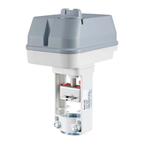
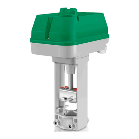
Regin RVAZ2-24A User manual

EN INSTRUCTION
RVAZ2-24A
IN20052 REV. A, 2021-06-11
CCaauuttiioonn!! Read and under tand the in truction before u ing the product.
CCaauuttiioonn!! En ure that the in tallation complie with local afety
regulation .
CCaauuttiioonn!! Before in tallation or maintenance, the power upply hould fir t
be di connected. In tallation or maintenance of thi unit hould only be
carried out by qualified per onnel. The manufacturer i not re pon ible
for any eventual damage or injury cau ed by inadequate kill during in tal-
lation, or through removal of or deactivation of any ecurity device .
Function
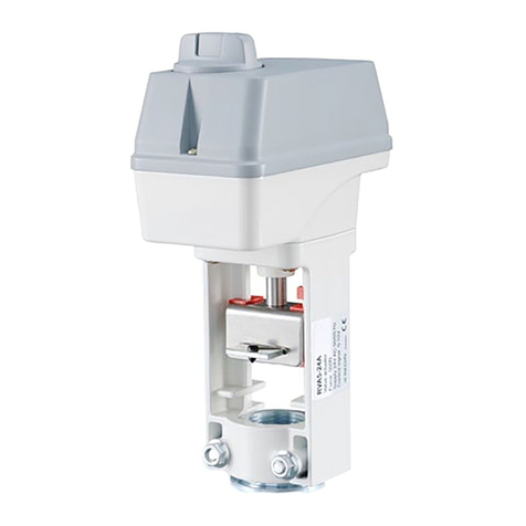
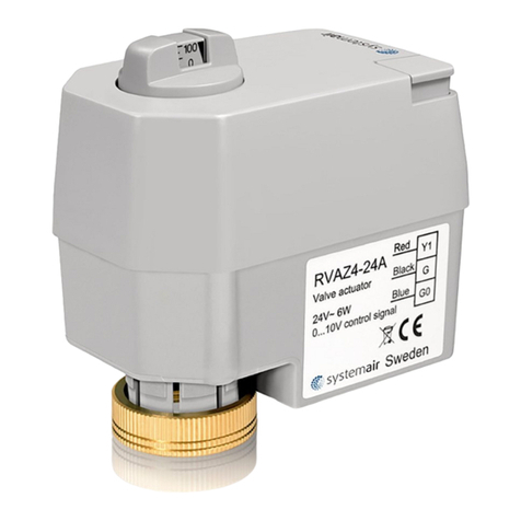
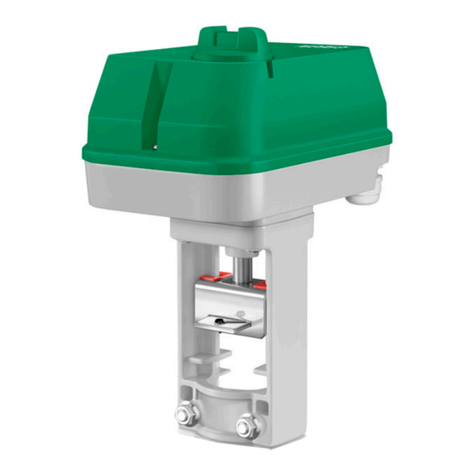
The RVAZ2-24A is an electromechanical actuator, intended for use in
applications such as heating, cooling, ventilation, chilled beams, fan-coils
and radiators. The actuator has DI switches for setting different
functions. The actuator is very versatile, suitable for a wide range of
valves.
Technical Data
Supply voltage 24 V AC/DC +/- 15 %
Control signal 0(2)…10 V / (0)4…20 mA
Power
consumption
2 W / 6 VA
Inrush current 1.8 A
Stroke 1-8.5 mm
Running time 5.5 s / mm
Force 200 N
Visual position
indicator
LED
Status and diag-
nostic indicator
LED
Manual override By 4 mm Allen key
Ambient
temperature
0…50 °C
Ambient humidity 95 % RH, non-condensing
Dimensions (W x H
x L)
50 x 88 x 93 mm
Protection class IP54
Cable length 1.5 m (halogen free)
In tallation
Start-up equence
When the power to the actuator is turned on, the actuator automatically
calibrates to determine closing point and stroke length of the valve. After
that it will proceed to normal operation according to control signal.
NNoottee!! The actuator will not work properly if no valve i in talled.
Mounting
Upside down installation is allowed, along with the standard horizontal
and vertical installation.
Fix the actuator to the valve using the connection nut, manual power is
sufficient.
CCaauuttiioonn!! Do not u e any tool a they can damage the actuator bracket.
Make ure the actuator tem i completely retracted before mounting it
on the valve.
Valve from other brand
See valve requirements in image below, when using valves from other
brands than Regin.
A
B
C
M30 x 1,5 mm*
D
Figure 1 A = min. 9.0 mm; B = max 17.5 mm; C = max Ø 20.5 mm; D = max 9.0
mm, * Adapters in range M2 x 1.5 mm to M30 x 1.5 mm are available. Contact
Regin for more information.
Wiring
The actuator has a halogen free connection cable fixed to the actuator.
Connect the supply voltage and control signal. If the actuator and
controller share a transformer, it is very important to keep the phase
separate from the zero, so the same pole is used as zero for both
controller and actuator, since this is the reference for the control signal.
1
2
3
4
24 V AC/DC (G) (+)
24 V AC/DC (G0) (-)
0…10 V DC input
0…10 V DC output
Figure 2 1 = Black; 2 = White; 3 = Red; 4 = Green
DIP witche
There are six DI switches for setting different functions. Follow the
table below for setting the DI switches.
Adjusted settings will be valid only after the next power-on.
Open the switch rubber seal with a screwdriver. Rotate the rubber seal
upwards to have access to the DI switches. If switch setting is changed
during operation the power need to be cut and put back on before the
settings to take effect.
NNoottee!! When the witch rubber eal i open, IP54 rating no longer applie .
RVAZ2-24A 1

DIP witch etting
The actuator is delivered with factory setting as shown in the table
below. All switches are set to "Off", except switch 1.
Off On
1
4
5
6
2
3
Off On
1 Actuator stem retract to
close
Actuator stem extend to
close
2 Flow: Equal percentage Flow: Linear
3 Direct action Reverse action
4 0…10 V input 2…10 V input
5 Plug: Linear Plug: Equal percentage
6 Input: 0…10V DC / 2…
10V DC
Input: 0…20 mA / 4…20
mA
SW1 Operational direction of the valve
Off: The valve is closed when the valve stem is in its highest position.
On: The valve is closed when the valve stem is in its lowest position.
SW2 Desired effective characteristic
Off: Effective equal percentage flow characteristics
On: Effective linear flow characteristics.
See more information under Characteristic curves.
SW3 Reverse/Direct operation
Off: Direct operation. The actuator opens the valve on increasing control
signal.
On: Reverse operation. The actuator closes the valve on increasing
control signal.
SW4 Control signal
Off: 0...10 V DC
On: 2...10 V DC
SW5 Valve flow characteristic
Off: Linear.
On: Equal percentage.
See more information under Characteristic curves.
SW6 Control signal type
Off: Voltage 0 (2)-10 V
On: Current 0 (4)-20mA
Characteri tic curve
The table below shows settings for switch 2 and switch 5. Switch 2 is the
desired effective function you want out of the valve and actuator
combination. Switch 5 is the flow characteristics of the valve itself.
Desired char-
acteristic
curve
Switch
coding
Characteristic
curve for
valve
Characteristic
curve for
actuator
Effective on
valve
Equal
percentage
Switch 2 = Off
Switch 5 = On
V
A
B
A
= %
B
V
Linear Switch 2 = On
Switch 5 = On
V
A
B
A
lin
B
V
Equal
percentage
Switch 2 = Off
Switch 5 = Off
V
A
B
A
= %
B
V
Linear Switch 2 = On
Switch 5 = Off
V
A
B
A
lin
B
V
A = Stroke; B = Signal
LED indication
The actuator has two LED lights with indications according to the table
below.
Green LED fixed light Actuator moving, under operation
Green LED quick flash Stroke adaption
Green LED slow flash (Flash twice +
Off 2 sec.)
0 % position
Green LED slow flash (Flash twice +
On 1 sec. + Off 1 sec.)
100 % position
Red LED lights End of SWs fault / more than 2 faults
Red LED quick flash One of End SWs fault
Red LED slow flash (Flash once + Off 2
sec.)
Settings changed during operation
Red LED slow flash (Flash twice + Off 2
sec.)
Auto stroke adapt fault
Manual override
To set the actuator to manual override, follow these steps:
1. Remove the manual override rubber seal with a screwdriver to have
access to the Allen key hole.
2. Use the 4 mm Allen key to turn the screw.
2
1
– Turn the Allen key clockwise to extend the actuator stem. This
closes the valve if the valve itself is closing when valve stem is
pushed into the valve.
– Turn the Allen key counterclockwise to retract the stem. This opens
the valve if the valve itself is closing when valve stem is pushed into
the valve.
Figure 3 Left: Valve is open when the valve stem is extended. Right: Valve is closed
when the valve stem is pushed into the valve.
NNoottee!! If the valve open when the valve tem i pu hed in, the function i
the oppo ite.
RVAZ2-24A 2

NNoottee!! When the manual override rubber eal i open, IP54 rating no lon-
ger applie .
This product carries the CE-mark. More information is available at
www.regincontrols.com.
Contact
AB Regin, Box 116, 428 22 Kållered, Sweden
Tel: +46 31 720 02 00, Fax: +46 31 720 02 50
www.regincontrols.com, [email protected]
SE INSTRUKTION
RVAZ2-24A
OObb eerrvveerraa!! Lä och för tå in truktionen innan du använder produkten.
OObb eerrvveerraa!! Se till att in tallationen uppfyller lokala
äkerhet be tämmel er.
OObb eerrvveerraa!! Innan in tallation eller underhåll må te matning pänningen
för t koppla från. In tallation eller underhåll av denna enhet ka enda t ut-
föra av kvalificerad per onal. Tillverkaren är inte an varig för eventuella
kador om or aka av felaktig in tallation och/eller inaktivering eller bort-
tagning av äkerhet anordningar.
Funktion
RVAZ2-24A Är ett elektromekaniskt ställdon, som används i
applikationer som värme, kylning, ventilation, fläktkonvektorer, fan-coils
och radiatorer. Ställdonet har DI -switchar för att kunna ställa in olika
funktioner. Ställdonet är väldigt mångsidigt och lämpligt för ett stort
utbud av ventiler.
Tekni ka data
Matningsspänning 24 V AC/DC ±15 %
Styrsignal 0(2)…10 V / (0)4…20 mA
Strömförbrukning 2 W / 6 VA
Motorström 1,8 A
Slaglängd 1-8,5 mm
Drifttid 5.5 s / mm
Kraft 200 N
Visuell
lägesindikering
Lysdiod
Status- och diagno-
stikindikering
Lysdiod
Manuell
manövrering
Med 4 mm insexnyckel
Omgivningstempe-
ratur
0…50 °C
Omgivande
luftfuktighet
95 % RH, icke-kondenserande
Dimensioner (B x H
x D)
50 x 88 x 93 mm
Skyddsklass IP54
Kabellängd 1,5 m (halogenfri)
In tallation
Upp tart ekven
När ställdonet spänningssätts kalibrerar ställdonet sig själv för att avgöra
ventilens slutpunkt och slaglängd. Efter detta återgår ställdonet till
normal drift enligt styrsignalen.
NNootteerraa!! Är ingen ventil in tallerad kommer tälldonet inte att fungera
ordentligt.
Montering
Det är tillåtet att installera ställdonet upp och ner, liksom den vanliga
horisontella och vertikala installationen.
Sätt ihop ställdonet med ventilen med hjälp av anslutningsmuttern.
Manuell kraft är tillräckligt.
OObb eerrvveerraa!! Använd inga verktyg, då de a kan kada tälldon fä tet. Se till
att tälldon axeln är helt indragen innan montering på ventilen.
Ventiler från andra märken
Se ventilkrav i nedan bild, vid användning av ventiler från andra märken
än Regin.
A
B
C
M30 x 1,5 mm*
D
Figur 1 A = min. 9.0 mm; B = max 17,5 mm; C = max Ø 20,5 mm; D = max 9,0
mm, * Adaptrar med räckvidd M2 x 1,5 mm till M30 x 1,5 mm är tillgängliga.
Kontakta Regin för mer information.
Inkoppling
Ställdonet har en fast halogenfri anslutningskabel.
Anslut matningsspänningen och styrsignalen. Om ställdon och regulator
delar transformator, är det väldigt viktigt att separera fasen från nollan, så
att samma pol används som nolla för både regulator och ställdon då detta
är styrsignalens referens.
1
2
3
4
24 V AC/DC (G) (+)
24 V AC/DC (G0) (-)
0…10 V DC input
0…10 V DC output
Figur 2 1 = Svart; 2 = Vit; 3 = Röd; 4 = Grön
DIP- witchar
Ställdonet har sex DI -switchar för att kunna ställa in olika funktioner.
Se nedan tabell för inställning av DI -switchar.
Justerade inställningar är endast tillgängliga efter nästa gång strömmen
slås på.
Öppna switchens gummiförsegling med en skruvmejseln. Rotera
gummiförseglingen uppåt för att komma åt DI -switcharna. Om switch-
inställningarna ändras under drift måste strömmen kopplas från för att
inställningarna ska få effekt.
NNootteerraa!! När witchen gummiför egling är öppen, gäller inte längre IP54-
kla ificeringen.
RVAZ2-24A 3

DIP- witchin tällningar
Ställdonet levereras med fabriksinställning, se tabellen nedan. Alla
switchar är satta till Off, förutom switch 1.
Off On
1
4
5
6
2
3
Off On
1 Ställdonsaxeln dras in för
att stänga.
Ställdonsaxeln trycks ut
för att stänga.
2 Flöde: Likprocentig Flöde: Linjär
3 Direkt verkan Omvänd verkan
4 0…10 V ingång 2…10 V ingång
5 Kägla: Linjär Kägla: Likprocentig
6 Ingång: 0…10V DC / 2…
10V DC
Ingång: 0…10 V / 4…20
mA
SW1 Ventilens arbetsriktning
Off: Ventilen är stängd när ventilspindeln är i sitt övre läge.
On: Ventilen är stängd när ventilspindeln är i sitt nedre läge.
SW2 Önskad effektkaraktäristik
Off: Effektiv likprocentig flödeskaraktäristik.
On: Effektiv linjär flödeskarakteristik.
See ytterligare information under Ställdonskaraktäristik.
SW3 Omvänd/Direkt verkan
Off: Direkt verkan. Ställdonet öppnar ventilen vid ökande styrsignal.
On: Omvänd verkan. Ställdonet stänger ventilen vid ökande styrsignal.
SW4 Styrsignal
Off: 0…10 V DC
On: 2…10 V DC
SW5 Ventilflödeskarakteristik
Off: Linjär.
On: Likprocentig.
Se ytterligare information under Ställdonskaraktäristik.
SW6 Styrsignal typ
Off: Spänning 0 (2)-10 V
On: Ström 0 (4)-20 mA
Ställdon karaktäri tik
Nedan tabell visar inställningar för switch 2 och switch 5. Switch 2 är
den önskade effektiva funktionen för ventil- och
ställdonskombinationen. Switch 5 är själva ventilens flödeskaraktäristik.
Önskad
karaktäristik
Switch-
kodning
Reglerkurva
för ventil
Reglerkurva
för ställdon
Effekt på ventil
Likprocentig Switch 2 = Off
Switch 5 = On
V
A
B
A
= %
B
V
Linjär Switch 2 = On
Switch 5 = On
V
A
B
A
lin
B
V
Likprocentig Switch 2 = Off
Switch 5 = Off
V
A
B
A
= %
B
V
Linjär Switch 2 = On
Switch 5 = Off
V
A
B
A
lin
B
V
A = Slaglängd; B = Signal
Ly diodindikering
Ställdonet har två lysdioder med indikeringar enligt nedanstående tabell.
Grön lysdiod fixerat ljus Ställdon i rörelse, under arbete
Grön lysdiod snabb blinkning Slaglängdsanpassning
Grön lysdiod långsam blinkning (Blinka
två gånger + Off 2 sek.)
0 % position
Grön lysdiod långsam blinkning (Blinka
två gånger + On 1 sek. + Off 2 sek.)
100 % position
Röda lysdioder Problem med ändlägesbrytare/Mer än
två fel
Röd lysdiod snabb blinkning Problem med ändlägesbrytare
Röd lysdiod långsam blinkning (Blinka
två gånger + Off 2 sek.)
Inställningar ändrade under drift
Röd lysdiod långsam blinkning (Blinka
två gånger + Off 2 sek.)
Auto slaglängd anpassningsfel
Manuell manövrering
För att sätta ställdonet i manuellt läge, följ nedanstående steg:
1. Med hjälp av en skruvmejsel, avlägsna gummiförseglingen över
manuell manövrering för att komma åt insexnyckelhålet.
2. Använd en 4 mm insexnyckel för att vrida på skruven.
2
1
– Vrid insexnyckeln medurs för att trycka ut ställdonsaxeln. Detta
stänger ventilen om ventilen stängs när ventilspindeln trycks in i
ventilen.
– Vrid insexnyckeln moturs för att dra tillbaka ställdonsaxeln. Detta
öppnar ventilen om ventilen stängs när ventilspindeln trycks in i
ventilen.
Figur 3 Vänster: Ventilen är öppen när spindeln är förlängd. Höger: Ventilen är stängd
när spindeln trycks in i ventilen.
NNootteerraa!! Om ventilen öppna när ventil pindeln är intryckt är funktionen
den mot atta.
NNootteerraa!! När gummiför eglingen för manuell över tyrning är öppen, gäller
inte längre IP54-kla ificeringen.
RVAZ2-24A 4

rodukten är CE-märkt. Mer information finns på www.regincontrols.
com.
Kontakt
AB Regin, Box 116, 428 22 Kållered, Sverige
Tel: +46 31 720 02 00, Fax: +46 31 720 02 50
www.regincontrols.com, [email protected]
DE INSTALLATIONSANLEITUNG
RVAZ2-24A
VVoorr iicchhtt Le en Sie die In tallation anleitung, bevor Sie da Produkt ver-
wenden, und beachten Sie ie.
VVoorr iicchhtt Vergewi ern Sie ich, da die In tallation den geltenden Sicher-
heit vor chriften ent pricht.
VVoorr iicchhtt Vor der In tallation oder Wartung mu zuer t die Stromver or-
gung unterbrochen werden. Die In tallation oder Wartung die e Gerät
darf nur von qualifizierten Fachkräften durchgeführt werden. Der Her tel-
ler haftet nicht für eventuelle Schäden oder Verletzungen, die durch man-
gelnde Fachkenntni e bei der In tallation oder durch da Entfernen bzw.
Deaktivieren von Sicherheit vorrichtungen ent tehen.
Funktion
Der RVAZ2-24A ist ein elektromechanischer Stellantrieb, der in
Anwendungen wie Heizung, Kühlung, Lüftung, Kühlbalken, Fan-Coils
und Heizkörper einsetzbar ist. Der Stellantrieb verfügt über DI -
Schalter zur Einstellung unterschiedlicher Funktionen. Der Stellantrieb
ist sehr vielseitig und für eine Vielzahl von Ventilen geeignet.
Techni che Daten
Versorgungsspan-
nung
24 V AC/DC +/- 15 %
Stellsignal 0(2)…10 V/(0)4…20 mA
Leistungsaufnah-
me
2 W / 6 VA
Einschaltstrom 1,8 A
Hub 1…8,5 mm
Laufzeit 5,5 s/mm
Stellkraft 200 N
Optische
Stellungsanzeige
LED
Status- und Diag-
nose-Anzeige
LED
Handverstellung Mittels 4 mm Inbusschlüssel
Umgebungstempe-
ratur
0…50 °C
Umgebungsfeuch-
te
95 % RH, nicht kondensierend
Maße (B x H x L) 50 x 88 x 93 mm
Schutzart IP54
Kabellänge 1,5 m (halogenfrei)
In tallation
Start equenz
Beim Einschalten führt der Stellantrieb automatisch eine Kalibrierung
durch, um den Schließpunkt und die Hublänge des Ventils zu
bestimmen. Danach wechselt er in den Normalbetrieb entsprechend
dem Stellsignal.
HHiinnwweeii !! Der Stellantrieb funktioniert nur dann ordnung gemäß, wenn
ein Ventil in talliert i t.
Montage
Eine Installation über Kopf ist ebenso zulässig wie die standardmäßige
horizontale und vertikale Installation.
Befestigen Sie den Stellantrieb mit der Überwurfmutter am Ventil,
wobei die Handkraft ausreicht.
VVoorr iicchhtt Verwenden Sie keine Werkzeuge, da ie die Halterung de Stell-
antrieb be chädigen können. Stellen Sie icher, da die Spindel de Stell-
antrieb voll tändig eingefahren i t, bevor er auf da Ventil montiert wird.
Ventile anderer Her teller
Beachten Sie die Ventilanforderungen gemäß Bild unten, wenn Sie
Ventile anderer Hersteller als Regin verwenden.
A
B
C
M30 x 1,5 mm*
D
Bild 1 A = min. 9,0 mm, B = max. 17,5 mm, C = max. Ø 20,5 mm, D = max.
9,0 mm * Es sind Adapter für den Bereich M2 x 1,5 mm bis M30 x 1,5 mm
erhältlich. Kontaktieren Sie Regin für weitere Informationen.
Verdrahtung
Der Stellantrieb verfügt über ein fest montiertes halogenfreies
Anschlusskabel.
Schließen Sie die Versorgungsspannung und das Regelsignal an. Teilen
sich Stellantrieb und Regler einen Trafo, muss darauf geachtet werden,
dass hase und Null getrennt bleiben, damit derselbe ol sowohl für den
Regler als auch für den Stellantrieb als Masse verwendet wird, da dieser
das Bezugspotenzial für das Stellsignal ist.
1
2
3
4
24 V AC/DC (G) (+)
24 V AC/DC (G0) (-)
0…10 V DC input
0…10 V DC output
Bild 2 1 = schwarz, 2 = weiß, 3 = rot, 4 = grün
DIP-Schalter
Zur Einstellung verschiedener Funktionen sind sechs DI -Schalter
vorhanden. Beachten Sie die folgende Tabelle zur Einstellung der DI -
Schalter.
Änderungen der Einstellungen werden erst nach dem nächsten
Einschalten wirksam.
Öffnen Sie die Gummidichtung des Schalters mit einem
Schraubendreher. Drehen Sie die Gummidichtung nach oben, um auf
die DI -Schalter zugreifen zu können. Wenn die Schaltereinstellung
während des Betriebs geändert wird, muss die Stromversorgung
unterbrochen und wieder eingeschaltet werden, damit die Einstellungen
wirksam werden.
HHiinnwweeii !! Bei geöffneter Gummidichtung de Schalter gilt die Schutzart
IP54 nicht mehr.
RVAZ2-24A 5
Ein tellungen DIP-Schalter
Der Stellantrieb wird mit den in der folgenden Tabelle aufgeführten
Werkseinstellungen ausgeliefert. Alle Schalter sind auf „Off“ gestellt,
außer Schalter 1.
Off On
1
4
5
6
2
3
Off On
1 Antriebsstange zum
Schließen einfahrend
Antriebsstange zum
Schließen ausfahrend.
2 Durchfluss:
Gleichprozentig
Durchfluss: Linear
3 Direkte Wirkung Umgekehrte Wirkung
4 0…10 V Eingang 2…10 V Eingang
5 Ventilkegel: Linear Ventilkegel:
Gleichprozentig
6 Eingang: 0…10 V DC/
2…10 V DC
Eingang: 0…20 mA/4…
20 mA
SW1 Wirkrichtung des Ventils
Off: Das Ventil ist geschlossen, wenn sich die Ventilspindel in der
höchsten osition befindet.
On: Das Ventil ist geschlossen, wenn sich die Ventilspindel in der
niedrigsten osition befindet.
SW2 Gewünschte effektive Kennlinie
Off: Effektive gleichprozentige Durchflusskennlinien
On: Effektive lineare Durchflusskennlinien.
Weitere Informationen unter Kennlinien.
SW3 Umgekehrter/Direkter Betrieb
Off: Direkter Betrieb. Der Stellantrieb öffnet das Ventil bei steigendem
Stellsignal.
On: Umgekehrter Betrieb. Der Stellantrieb schließt das Ventil bei
steigendem Stellsignal.
SW4 Stellsignal
Off: 0…10 V DC
On: 2…10 V DC
SW5 Ventildurchflusskennlinie
Off: Linear.
On: Gleichprozentig.
Weitere Informationen unter Kennlinien.
SW6 Stellsignal Typ
Off: Spannung 0(2)…10 V
On: Strom 0(4)…20 mA
Kennlinien
Folgende Tabelle zeigt die Einstellungen für Schalter 2 und Schalter 5.
Schalter 2 ist die gewünschte effektive Arbeitsweise, die Sie mit der
Kombination aus Ventil und Stellantrieb erreichen möchten. Schalter 5
ist die Durchflusskennlinie des Ventils selbst.
Gewünschte
Kennlinie
Schalter
Positionen
Ventilkennli-
nie
Antriebs-
kennlinie
Effektiv am
Ventil
Gleichprozen-
tig
Schalter 2 =
Off
Schalter 5 =
On
V
A
B
A
= %
B
V
Linear Schalter 2 =
On
Schalter 5 =
On
V
A
B
A
lin
B
V
Gleichprozen-
tig
Schalter 2 =
Off
Schalter 5 =
Off
V
A
B
A
= %
B
V
Linear Schalter 2 =
On
Schalter 5 =
Off
V
A
B
A
lin
B
V
A = Hub, B = Signal
LED-Anzeige
Der Stellantrieb verfügt über zwei LEDs, die Folgendes anzeigen.
Grüne LED Dauerlicht Stellantrieb bewegt sich, in Betrieb
Grüne LED blinkt schnell Hubanpassung
Grüne LED blinkt langsam (2 x blinken
+ 2 s Pause)
0 % Position
Grüne LED blinkt langsam (2 x blinken
+ 1 s leuchten + 1 s Pause)
100 % Position
Rote LED Dauerlicht Ende SW-Fehler/mehr als zwei Fehler
Rote LED blinkt schnell Ende eines SW-Fehlers
Rote LED blinkt langsam (1 x blinken
+ 2 s Pause)
Einstellungen während des Betriebs
geändert
Rote LED blinkt langsam (2 x blinken
+ 2 s Pause)
Fehler automatische Hubanpassung
Handver tellung
Zur Handsteuerung des Stellantriebs gehen Sie wie folgt vor:
1. Entfernen Sie die Gummidichtung der Handverstellung mit einem
Schraubendreher, um Zugang für den Inbusschlüssel zu erhalten.
2. Benutzen Sie zum Drehen der Schraube einen 4 mm Inbusschlüssel.
2
1
– Drehen Sie den Inbusschlüssel im Uhrzeigersinn, um die
Antriebsstange auszufahren. Dadurch wird das Ventil geschlossen,
wenn es sich um ein Ventil handelt, das durch Hineinschieben der
Ventilspindel schließt.
– Drehen Sie den Inbusschlüssel gegen den Uhrzeigersinn, um die
Antriebsstange einzufahren. Dadurch wird das Ventil geöffnet,
wenn es sich um ein Ventil handelt, das durch Hineinschieben der
Ventilspindel schließt.
Bild 3 Links: Das Ventil ist geöffnet, wenn die Ventilspindel ausgefahren ist. Rechts:
Das Ventil ist geschlossen, wenn die Ventilspindel in das Ventil hineingeschoben ist.
RVAZ2-24A 6

HHiinnwweeii !! Wenn da Ventil beim Hinein chieben der Ventil pindel öffnet,
i t die Funktion genau umgekehrt.
HHiinnwweeii !! Bei geöffneter Gummidichtung der Handver tellung i t die
Schutzart IP54 nicht mehr gültig.
Dieses rodukt trägt das CE-Zeichen. Weitere Informationen finden Sie
unter www.regincontrols.de.
Kontakt
Regin Controls Deutschland GmbH, Haynauer Str. 49, 12249 Berlin,
Deutschland
Tel.: +49 30 77 99 4-0, Fax: +49 30 77 99 4-79
www.regincontrols.de, [email protected]
FR INSTRUCTION
RVAZ2-24A
AAtttteennttiioonn !! Veuillez lire attentivement le in truction avant d’utili er le
produit.
AAtttteennttiioonn !! A urez-vou que l’in tallation e t conforme aux norme de
écurité locale .
AAtttteennttiioonn !! Avant de procéder à l’in tallation ou à la maintenance de l’ap-
pareil, il convient de couper l’alimentation électrique. Le opération d’in -
tallation et de maintenance doivent être effectuée par un profe ionnel
qualifié. Le fabricant ne pourra être tenu re pon able d’éventuel domma-
ge ou ble ure cau é par une in tallation défectueu e du produit, ou
par la dé activation de di po itif de écurité.
Fonctionnement
LeRVAZ2-24A est un actionneur électromécanique, destiné à être
utilisé dans des applications telles que le chauffage, le refroidissement, la
ventilation, les poutres froides, les ventilo-convecteurs et les radiateurs.
L’actionneur est doté de commutateurs DI pour le réglage de
différentes fonctions. Il est particulièrement polyvalent et convient à une
large gamme de vannes.
Caractéri tique technique
Tension
d’alimentation
24 V AC/DC +/- 15 %
Signal de
commande
0(2)…10 V / (0)4…20 mA
Puissance
consommée
2 W / 6 VA
Courant d’appel 1,8 A
Course 1 à 8,5 mm
Durée de
fonctionnement
5,5 s / mm
Couple 200 N
Indicateur de
position
LED
Indicateur d’état et
de diagnostic
LED
Commande
manuelle
Par clé Allen de 4 mm
Température
ambiante
0…50 °C
Humidité ambiante 95 % HR, sans condensation
Dimensions (L x H
x L)
50 x 88 x 93 mm
Indice de
protection
IP54
Longueur du câble 1,5 m (sans halogène)
In tallation
Séquence de démarrage
Lorsque l’actionneur est mis sous tension, il se calibre automatiquement
pour déterminer le point de fermeture et la longueur de course de la
vanne. Ensuite, il passe au fonctionnement normal dépendant du signal
de commande.
NNBB !! L’actionneur ne fonctionnera pa correctement i aucune vanne n’e t
in tallée.
Montage
Une installation verticale actionneur sous la vanne est possible, ainsi
qu’une installation horizontale ou verticale standard.
Fixez l’actionneur à la vanne à l’aide de la bague, un serrage manuel est
suffisant.
AAtttteennttiioonn !! Ne pa utili er d’outil , car il peuvent endommager le up-
port de l’actionneur. La tige de l’actionneur doit être complètement ré-
tractée avant d’être montée ur la vanne.
Vanne d’autre marque
Voir les spécifications des vannes sur l’image ci-dessous, pour l’utilisation
de vannes d’autres marques que Regin.
A
B
C
M30 x 1,5 mm*
D
Fig. 1 A = min. 9.0 mm ; B = max 17.5 mm ; C = max Ø 20.5 mm ; D = max 9.0
mm, * Des adaptateurs du type M2 x 1.5 mm à M30 x 1.5 mm sont disponibles.
Merci de contacter Regin pour plus d’informations.
Raccordement
L’actionneur est équipé d’un câble de raccordement pré-connecté.
Connectez la tension d’alimentation et le signal de commande. Si
l’actionneur et le régulateur partagent un transformateur, il est
primordial repérer la phase du zéro, ainsi le même pôle est utilisé
comme zéro pour le régulateur et l’actionneur, car c’est la référence pour
le signal de commande.
1
2
3
4
24 V AC/DC (G) (+)
24 V AC/DC (G0) (-)
0…10 V DC input
0…10 V DC output
Fig. 2 1 = Noir ; 2 = Blanc ; 3 = Rouge ; 4 = Vert
RVAZ2-24A 7

Commutateur DIP
Il y a six commutateurs DI pour régler différentes fonctions. Voir le
tableau ci-dessous pour plus de détails.
Les nouveaux réglages prendront effet à la prochaine mise sous tension.
Ouvrez le joint en caoutchouc du commutateur à l’aide d’un tournevis.
Tournez le joint en caoutchouc vers le haut pour avoir accès aux
commutateurs DI . Si le réglage d’un commutateur est modifié pendant
le fonctionnement, il faut couper et rétablir l’alimentation pour que les
réglages prennent effet.
NNBB !! Lor que le joint en caoutchouc e t ouvert, l'indice de protection IP54
n’e t plu applicable.
Réglage de commutateur DIP
L’actionneur est livré avec les paramètres d’usine indiqués dans le
tableau ci-dessous. Tous les commutateurs sont réglés sur « Off », sauf le
commutateur 1.
Off On
1
4
5
6
2
3
Arrêt Marche
1 La tige de l’actionneur se
rétracte pour se fermer
La tige de l’actionneur
sort pour fermer.
2 Caractéristiques de débit :
Pourcentage égal
Caractéristiques de dé-
bit : Linéaire
3 Action directe Action inverse
4 Entrée 0...10 V Entrée 2...10 V
5 Clapet : Linéaire Clapet : Pourcentage
égal
6 Entrée : 0…10V DC / 2…
10V DC
Entrée : 0…20 mA / 4…
20 mA
SW1 Sens de fonctionnement de la vanne
Off : La vanne est fermée lorsque la tige de la vanne est dans sa position
la plus haute.
On : La vanne est fermée lorsque la tige de la vanne est dans sa position
la plus basse.
SW2 Caractéristique de débit souhaitée
Off : Caractéristiques de débit à pourcentage égal.
On : Caractéristiques de débit linéaire
Voir plus d’informations sous Courbes caractéristiques.
SW3 Fonctionnement inverse/direct
Off : Fonctionnement direct. L’actionneur ouvre la vanne lorsque le
signal de commande augmente
On : Action inversée. L’actionneur ferme la vanne quand le signal de
commande augmente.
SW4 Signal de commande
Off : 0...10 V DC
On : 2...10 V DC
SW5 Caractéristique de débit de la vanne
Off : Linéaire.
On : ourcentage égal.
Voir plus d’informations sous Courbes caractéristiques.
SW6 Signal de commande type
Off : Tension 0 (2)-10 V
On : Courant 0 (4)-20mA
Courbe caractéri tique
Le tableau ci-dessous montre les réglages des commutateurs 2 et 5. Le
commutateur 2 correspond à la fonction réelle que vous souhaitez
obtenir de la combinaison vanne/actionneur. Le commutateur 5
correspond aux caractéristiques de débit de la vanne elle-même.
Courbe ca-
ractéristique
souhaitée
Codage du
commutateur
Courbe ca-
ractéristique
de la vanne
Courbe ca-
ractéristique
de
l’actionneur
Effet sur la
vanne
Pourcentage
égal
Commutateur2
= Off
Commutateur5
= On
V
A
B
A
= %
B
V
Linéaire Commutateur2
= On
Commutateur5
= On
V
A
B
A
lin
B
V
Pourcentage
égal
Commutateur2
= Off
Commutateur5
= Off
V
A
B
A
= %
B
V
Linéaire Commutateur2
= On
Commutateur5
= Off
V
A
B
A
lin
B
V
A = Course ; B = Signal
Témoin LED
L’actionneur possède deux voyants LED avec des indications selon le
tableau ci-dessous.
LED verte fixe Actionneur en mouvement, en cours de
fonctionnement
LED verte à clignotement rapide Adaptation de la course
Clignotement lent de la LED verte
(deux clignotements + Off 2 sec.)
Position 0 %
Clignotement lent de la LED verte (2
fois + On 1 sec. + Off 1 sec.)
Position 100 %
LED rouge allumée Erreur sur les fins de course internes /
plus de 2 erreurs
LED rouge à clignotement rapide Erreur sur un fin de course interne
Clignotement lent de la LED rouge (cli-
gnotement unique + Off 2 sec.)
Modification des paramètres pendant le
fonctionnement
Clignotement lent de la LED rouge
(deux clignotements + Off 2 sec.)
Erreur d’adaptation automatique de la
course
Commande manuelle
our régler l’actionneur en commande manuelle, suivez ces étapes :
1. Retirez le joint en caoutchouc de la commande manuelle à l’aide
d’un tournevis pour avoir accès au trou de la clé Allen.
2. Utilisez une clé Allen de 4 mm pour tourner la vis.
RVAZ2-24A 8

2
1
– Tournez la clé Allen dans le sens des aiguilles d’une montre pour
allonger la tige de l’actionneur. Cela permet de fermer la vanne si
elle se ferme lorsque la tige est poussée vers l’intérieur.
– Tournez la clé Allen dans le sens inverse des aiguilles d’une montre
pour rétracter la tige. Ceci ouvre la vanne si la vanne elle se ferme
lorsque la tige est rentrée.
Fig. 3 Gauche : La vanne est ouverte lorsque la tige de la vanne est sortie. Droite : La
vanne est fermée lorsque la tige est rentrée.
NNBB !! Si la vanne ’ouvre lor que la tige de la vanne e t pou ée, la fonction
e t inver e.
NNBB !! Lor que le joint en caoutchouc de la commande manuelle e t ou-
vert, l'indice de protection IP54 ne ’applique plu .
Ce produit porte le marquage CE. our plus d’information, veuillez
consulter le site web www.regincontrols.fr.
Contact
AB Regin, Box 116, 428 22 Kållered, Suède
Tél. : +46 31 720 02 00, Fax : +46 31 720 02 50
www.regincontrols.com, [email protected]
RVAZ2-24A 9
Table of contents
Languages:
Other Regin Controllers manuals

Regin
Regin REGIO EEDO User manual

Regin
Regin PULSER-X/D User manual

Regin
Regin Regio Midi User manual

Regin
Regin RVAZ4L1-24A User manual

Regin
Regin RVAR5-230 User manual

Regin
Regin TTC 2000 User manual

Regin
Regin TT-S6/D User manual

Regin
Regin Exigo User manual

Regin
Regin OPTIGO OP10 User manual

Regin
Regin RVAPC-24A User manual

Regin
Regin Optigo OP5U User manual

Regin
Regin Corrigo User manual

Regin
Regin RCF Series User manual

Regin
Regin Regio Eddo User manual

Regin
Regin REGIO ARDO User manual

Regin
Regin CORRIGO L10 User manual

Regin
Regin TTC40FX User manual

Regin
Regin PULSER X010 Series User manual

Regin
Regin PULSER-ADD User manual

Regin
Regin RVAZ4-24A User manual