manuals.online logo
Brands
  1. Home
  2. •
  3. Brands
  4. •
  5. NuAire
  6. •
  7. Fan
  8. •
  9. NuAire ES-MEV Assembly instructions

NuAire ES-MEV Assembly instructions

0.01
1
ES-MEV - Hints & Tips
GUIDANCE NOTES 10
Technical Support Dept. T. 02920 858585 F. 02920 858586
Leaflet Number 671414 January 2010
Calibration
Status
30
0
60
Run-on
(mins)
50
10
90
Max
Airflow
(l/s)
50
10
90
Min
Airflow
(l/s)
TEST BUTTON
SL RUN ON
MAX SPEED
ADJUST
MIN SPEED
ADJUST
LED
continued overleaf.
Nuaire Group Western Industrial Estate Caerphilly United Kingdom CF83 1NA
Telephone: 029 2085 8200 Facsimile: 029 2088 7033 Email: [email protected] www.nuaire.co.uk
N
L
SL
Do not use
To OPUS-SPD
speed control
Internal
humidity adj.
To remote
fail indicator
ES-MEV-AVI
Calibration
Status
30
0
60
Run-on
(mins)
50
10
90
Max
Airflow
(l/s)
50
10
90
Min
Airflow
(l/s)
LVT NET TR
1.0. On Installation
Follow the installation and maintenance document
671266 for ES-MEV, paying particular attention to;
1.1. The chosen location for installation.
a). Mounting the unit using the integral mounting
bracket supplied.
b). Mount the unit on a non reverberant surface.
c). The unit can be mounted at any angle.
d). Make sure that when the unit is mounted
sufficient space is left around the unit for
maintenance and the fixing of the ducting.
e). If installed with flexible duct special care/
consideration should be made to prevent the
duct being closed off, cracked or twisted,
introducing a high resistance on the system.
1.2. Electrical.
a). Pay particular attention to electrical
connections referring to the I&M for correct
method.
b). Isolation of the unit and any switched live
circuits should be achieved through the same
isolator.
230V Switched live
1.3 Setting to work
When initially powered the ES-MEV will self
calibrate, it will try to achieve the duties set by
the MAX and MIN set points.
The calibration process can take around 2 minutes
and is as follows:
■Unit runs to full speed. (Faster than the max
set point).
■The unit will slow down and eventually stop.
■A 10 second wait.
■It will restart and run at ¼ speed.
■The unit then settles to the MIN speed.
If, during this process the red LED should illuminate,
ensure there are no switched live or boost signals
present.
Upon completion of the calibration process apply a
switched live (SL), the fan speed and duty should
increase to that of the MAX set point.
When testing a system
a). The ‘dial a duty’ set points should be positioned
with the MAX at MAX and MIN at MIN, i.e.
giving the widest possible speed control range.
b). On an existing installation it is important to
observe and note these duty positions should
it be necessary to return to them later.
c). The SL run on should be set to minimum to
reduce the run on time during test, it is
important to note the position set should it be
necessary to return to it later.
Circuit board connections.
Complaint Cause and correct Complaint Cause and correct
Not powering Red LED flashing
up. 6 times after start
start up procedure
has finished.
Red LED flashing
7 times after start
start up procedure
has finished.
Not working High airflow
would usually but no
suggest that it discharge to
has at sometime atmosphere.
functioned
correctly.
Noise. Low airflow
but fan speed
high.
Ensure mains power to unit.
The green LED should flash.
Ensure unit hasn’t been
switched off or isolated and
that the local fuse hasn’t blown.
Ensure unit hasn’t been
switched off or that the local
fuse hasn’t blown.
LED flash but fan doesn’t run
signifies a motor failure,
replace the fan internal.
If electricity present, power off,
wait and power on again – this
may restart the unit.
Impeller fouling case.
Replace internal.
Contaminated impeller causing
an out of balance. Lightly brush
away excess dirt taking care
not to disturb balance weights.
Unit not mounted on a flat
surface causing distortion,
adjust fixing.
High system pressure, causing
unit to run at high speed to
obtain duty selected. (see right).
Fan is unable to achieve the
duty required. Excessive system
pressure. Adjust set point and
press the calibrate button.
Check for blocked/crushed
ductwork, closed air valves,
blocked external air bricks/
grilles etc. Ensure pressure pipe
from the blower is correctly
attached to the pressure switch.
Motor failure - replace internals
Low system pressure:
• Ensure all ducting is
connected from fan to
atmosphere.
High system pressure,
check for:
• Dirty filters
• Backdraught shutters
jammed shut
• Blocked outlet grilles.
• Long ducted runs
• Twists, bends or crushed
flexible duct work
2
GUIDANCE NOTES 10
Technical Support Dept. T. 02920 858585 F. 02920 858586
ES-MEV - Hints & Tips
Leaflet Number 671414 January 2010
0.01
2.0 On Maintenance
2.1 Motors contain sealed for life bearings, no
lubrication is necessary.
2.2 A washable filter is fitted, we recommended
that all unit filters are inspected and cleaned
(wash in light detergent and dry before
refitting) after the first six months and
determine the maintenance frequency there
after by the rate and type of contamination.
2.3 Lightly brush excess dirt from unit cases and
fan impellers taking care not to disturb
impeller balance weights – if washing is
necessary apply a light detergent and dry.
3.0 On Spares
Should a defect arise during installation or ‘setting
to work of the unit. Firstly isolate the unit and re
apply the power after 10 seconds. Check all wiring
is correct and no boost signal is present. If a fault
still exists, in the first instance please call our
technical department on 029 2085 8585.
The internal parts are exchangeable and can be
removed as a whole component or if necessary it
is possible to replace the main PCB.
Component Spares Part No.
Complete internal fan/control assembly 774941-P
Dial a duty PCB 830178
Filter 070784
4.0 Trouble Shooting
Complaints are generally that the unit is ‘not
working’ so it will be first necessary to distinguish
between an electrical/mechanical malfunction or
whether the unit operates but simply fails to
extract air. (see table below for possible problems
and corrective procedures).
GUIDANCE NOTES 10
Technical Support Dept. T. 02920 858585 F. 02920 858586
ES-MEV - Hints & Tips
Leaflet Number 671414 January 2010
0.01
5.0 ES-MEV Replacement of
the 830178 PCB
5.1 The replacement of the PCB should be under
taken when the fault finding procedure has
identified a problem in this area and cannot be
rectified by re-adjustment of the duties
required.
5.2. Isolate unit. (See unit Figure below).
Take note of the duties set as the unit may
have been commissioned for air flow and will
have to be reset once the PCB is replaced.
Remove Live, Neutral, Switched live and earth
connections.
Remove the 2 ‘mate-n-lock’ plugs that inter
connect the PCB’s.
Undo the central mounting screw and lift
the PCB.
Remove the pressure pipe from the differential
pressure sensor. (NB Use only the bottom
spigotted inlet).
To replace, reverse the above procedure.
MAINS CONNECTION
PRESSURE PIPE
MOUNTING SCREW
2 MATE-N-LOCK PLUGS
SL RUN ON
MAX
MIN
830178 PCB with protective cover removed.

Other NuAire Fan manuals

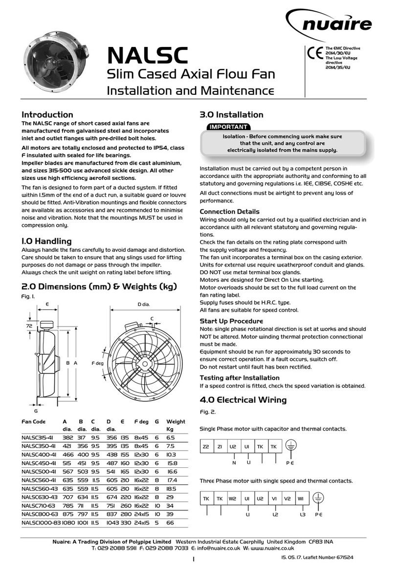
NuAire DuctMaster DSA Instruction Manual

NuAire

NuAire DuctMaster DSA Instruction Manual

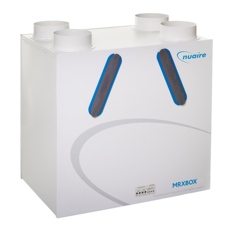
NuAire MRXBOXAB-ECO3B-AESW User manual

NuAire

NuAire MRXBOXAB-ECO3B-AESW User manual

NuAire XBOXER XBC Series Assembly instructions

NuAire

NuAire XBOXER XBC Series Assembly instructions

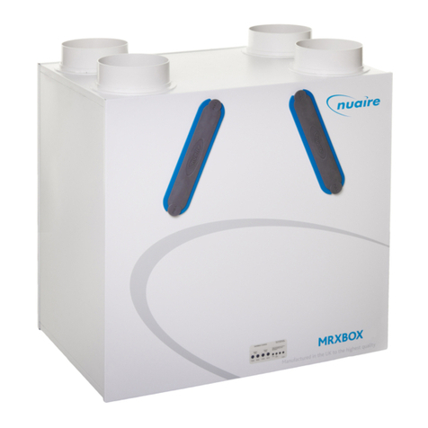
NuAire MRXBOX-SIL2 Instruction Manual

NuAire

NuAire MRXBOX-SIL2 Instruction Manual

NuAire MRXBOXAB-ECO2B-1Z User manual

NuAire

NuAire MRXBOXAB-ECO2B-1Z User manual

NuAire OPUS 40 User manual

NuAire

NuAire OPUS 40 User manual

NuAire AVS Series Instruction Manual

NuAire

NuAire AVS Series Instruction Manual

NuAire MEV-DC2 Instruction Manual

NuAire

NuAire MEV-DC2 Instruction Manual

NuAire AX User manual

NuAire

NuAire AX User manual

NuAire FLAT2000 L User manual

NuAire

NuAire FLAT2000 L User manual

NuAire DRI-365 User manual

NuAire

NuAire DRI-365 User manual

NuAire DRI-ECO-HEAT-HCS User manual

NuAire

NuAire DRI-ECO-HEAT-HCS User manual

NuAire MRXBOXAB-ECO3-SW User manual

NuAire

NuAire MRXBOXAB-ECO3-SW User manual

NuAire DRI-ECO3S-HEAT-HC User manual

NuAire

NuAire DRI-ECO3S-HEAT-HC User manual

NuAire MRXBOX-ECO2-OH Instruction Manual

NuAire

NuAire MRXBOX-ECO2-OH Instruction Manual

NuAire Sunwarm Air Installation guide

NuAire

NuAire Sunwarm Air Installation guide

NuAire SLIMAIRE/NA Series Instruction Manual

NuAire

NuAire SLIMAIRE/NA Series Instruction Manual

NuAire XB-EFA-8L-BK User guide

NuAire

NuAire XB-EFA-8L-BK User guide

NuAire SVTC8 User manual

NuAire

NuAire SVTC8 User manual

NuAire ECOSMART AIRMOVER Instruction Manual

NuAire

NuAire ECOSMART AIRMOVER Instruction Manual

NuAire XS Series Instruction Manual

NuAire

NuAire XS Series Instruction Manual

NuAire AIRMOVER DSM Series Instruction Manual

NuAire

NuAire AIRMOVER DSM Series Instruction Manual

NuAire MRXBOX95B-LPIH Instruction Manual

NuAire

NuAire MRXBOX95B-LPIH Instruction Manual

NuAire MEV-X Instruction Manual

NuAire

NuAire MEV-X Instruction Manual

Popular Fan manuals by other brands

Mitsubishi Electric P-251TW-HK installation manual

Mitsubishi Electric

Mitsubishi Electric P-251TW-HK installation manual

TJERNLUND HSJ manual

TJERNLUND

TJERNLUND HSJ manual

GOSUN BREEZE user manual

GOSUN

GOSUN BREEZE user manual

Global 246340 instruction manual

Global

Global 246340 instruction manual

TemperZone IMDL 40Y Installation & maintenance

TemperZone

TemperZone IMDL 40Y Installation & maintenance

Exhausto VEX310T Assembly and installation

Exhausto

Exhausto VEX310T Assembly and installation

MiniSun 19500 manual

MiniSun

MiniSun 19500 manual

DeKo B 450 Instructions for use

DeKo

DeKo B 450 Instructions for use

Dantherm HCC 2 ALU Service manual

Dantherm

Dantherm HCC 2 ALU Service manual

Harbor Breeze CUMBERLAND 42476 manual

Harbor Breeze

Harbor Breeze CUMBERLAND 42476 manual

LUCCI Air ATLANTA LD-56 ATL Installation, operation, maintenance & warranty information

LUCCI Air

LUCCI Air ATLANTA LD-56 ATL Installation, operation, maintenance & warranty information

Mistral MBF851WH instruction manual

Mistral

Mistral MBF851WH instruction manual

Minka WESTFORD instruction manual

Minka

Minka WESTFORD instruction manual

Titon HRV20 Q Plus ECO product manual

Titon

Titon HRV20 Q Plus ECO product manual

S&P HCM Series manual

S&P

S&P HCM Series manual

impact Crate Fan installation instructions

impact

impact Crate Fan installation instructions

NuTone 763RLN installation instructions

NuTone

NuTone 763RLN installation instructions

Carrier FX4D 019 installation instructions

Carrier

Carrier FX4D 019 installation instructions

manuals.online logo
manuals.online logoBrands
  • About & Mission
  • Contact us
  • Privacy Policy
  • Terms and Conditions

Copyright 2025 Manuals.Online. All Rights Reserved.