manuals.online logo
Brands
  1. Home
  2. •
  3. Brands
  4. •
  5. NuAire
  6. •
  7. Fan
  8. •
  9. NuAire MVHR-LP-AC Instruction Manual

NuAire MVHR-LP-AC Instruction Manual

1Leaflet Number 671350 July 2007
F gure 1.
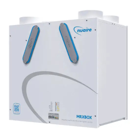
MVHR-LP-AC
Mechan cal Vent lat on w th Heat Recovery
Installat on and Ma ntenance
F gure 3.
Cut through the
acoust c foam round
the c rcumference of
the damper.
Damper can be
sw velled on the
2 body cas ng
h nges.
Fx ng screw hole.
Bracket tongues
engage w th cas ng
slots, then un t
rotated up to al gn
wth f x ng
screw hole.
Slots n cas ng
e ther s de of
un t to allow
alternat ve
mount ng opt on.
F gure 4.
When sp got s n
pos t on, damper can
be adjusted us ng a
screwdr ver.
F gure 2.
D scharge
Supply
Supply
Extract
Extract
Intake
Access covers on unders de.
1.0 Introduct on
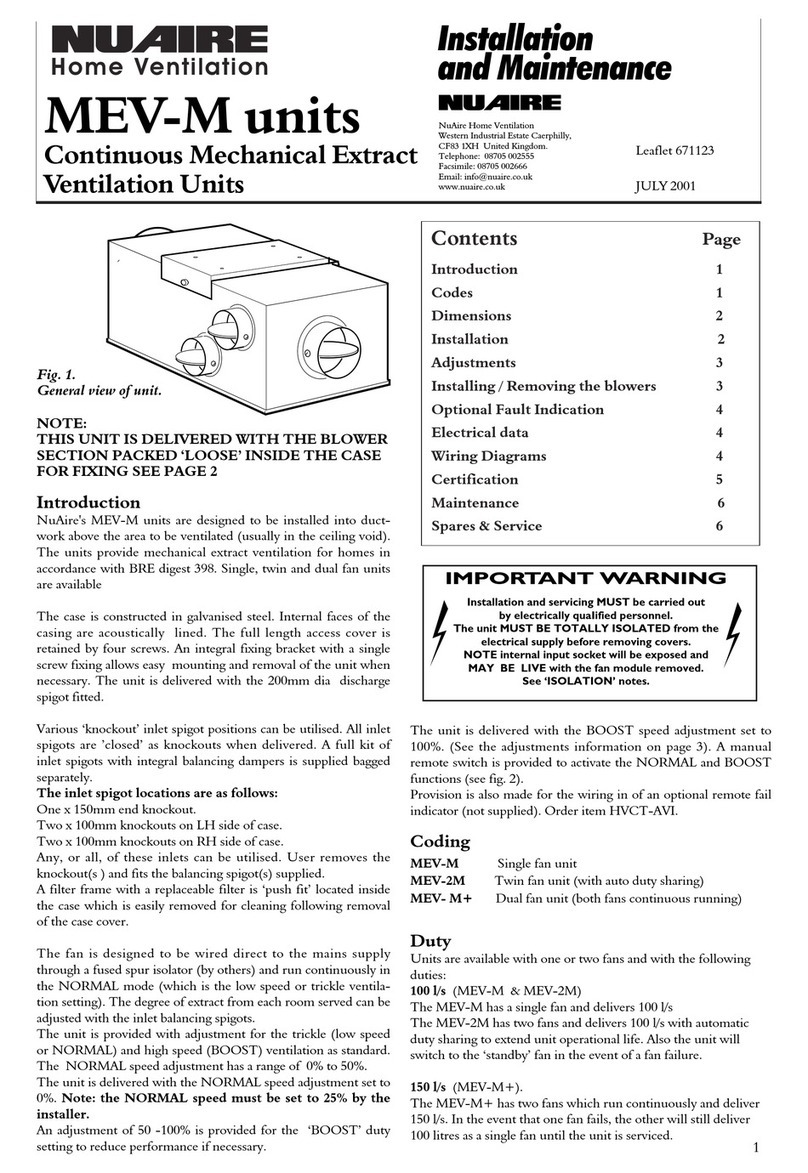
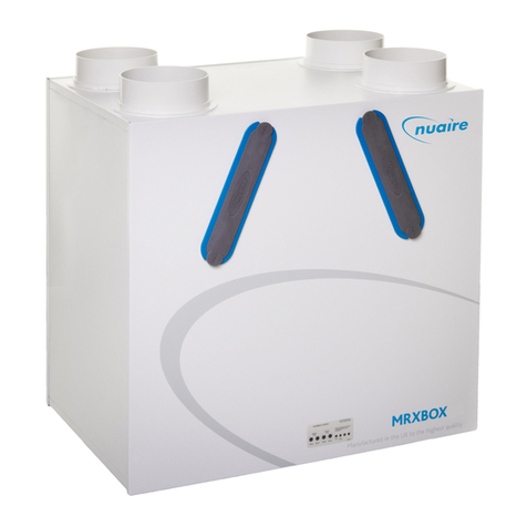
The Nua re MVHR-LP-AC un t s des gned to prov de
mechan cal supply and extract vent lat on w th heat
recovery.
The un t s f tted w th two fans w th ndependant adjustable
speed control. A plate heat-exchange constructed from
alum n um s used to prov de up to 70% heat recovery.
2.0 Installat on
Installat on must be carr ed out by competent personnel
conform ng to all statutory and govern ng regulat ons
nclud ng the current w r ng and CDM regulat ons.
Spec al attent on must be pa d to the s ze and we ght of the
un t and the handl ng method to locate the un t n s tu.
The un t s des gned to be ce l ng mounted n the hor zontal
plane w th access panels and condensate dra n on the
unders de.
The fan must be f tted ndoors, away from any d rect
sources of heat, water spray or mo sture generat on.
Temperature range -5OC to 40OC.
Please note a clear work ng space s requ red around
the nstalled un t to allow the cover to be removed and
prov de suff c ent access for ma ntenance such as f lter
change.
The fan s des gned to be w red d rect to the ma ns supply
through a fused spur solator (by others).
W th the un t f xed n pos t on and work ng from underneath
the nstallat on br ng the ma ns w r ng through the chosen
rubber cable entry grommet at the new connect on box.
Add t onal grommeted holes are prov ded to allow add t onal
w r ng to each blower.
The ntegral mount ng bracket suppl ed can be offered up to
pos t on, the f x ng po nts marked through and the bracket
nstalled w th 4 screws (by others).
Offer the un t nto pos t on and locate the bracket nto the
slots n the case before f x ng w th the s ngle bracket f x ng
screw.
Var ous damper/ nlet sp got pos t ons can be ut l sed as
requ red to su t the system ductwork and extract gr lles.
To reduce a r leakage, sp gots should be sealed to the un t
by s l cone sealant or s m lar (by others).
All nlet dampers are ’closed’ as knockouts when del vered
but can be opened us ng a sharp kn fe. (See f gure 3).
After the sp got has been f xed adjust the damper w th a
screwdr ver. (See f gure 4).
See f gure 5 for sp got locat on and s zes.
The condensate dra n must be connected v a a trap nto
e ther a su table waste water system or to the outs de of
the bu ld ng. Th s connect on must be detachable to allow
access nto the un t. Ensure the p pe from the condensate
dra n falls away from the un t.
Nua re L m ted Western Industr al Estate Caerph lly Un ted K ngdom CF83 1NA
T: 029 2088 5911 F: 029 2088 7033 E: nfo@nua re.co.uk W: www.nua re.co.uk
For good EMC eng neer ng pract ce, any sensor cables
or sw tched l ve cables should not be
placed w th n 50mm of other cables or on the same
metal cable tray as other cables.
Isolat on - Before commenc ng work make sure
that the un t, sw tched l ve and Nua re control are
electr cally solated from the ma ns supply.
Please note th s product must be earthed.
2Leaflet Number 671350 July 2007
Installat on and Ma ntenance MVHR-LP-AC Mechan cal Vent lat on w th Heat Recovery
850
685
637
Bracket
fixing
VIEW FROM UNDERSIDE WITH COVER REMOVED
SIDE VIEW
MOUNTING BRACKET TOP VIEW
Mounting bracket
END VIEW
Single screwunit fixing
185
10
250
4 holes
7.5mm dia.
4x spigot knockouts 1 x 125mm dia. and 3 x 100mm dia.
for each supply and extract system
Cable entry 20mm
4 x end spigot
knockouts
100mm dia.
Mains
connection
box
125 dia. 100 dia.
extract extract
100 dia.
extract
100 dia.
extract
100 dia.
supply
100 dia.
supply
125 dia. 100 dia.
supply supply
125 dia.
Intake
125 dia.
discharge
Condensate drain 022 OD
Weight: 25kg
N
L
SL
TRICKLEBOOST
ABCDEFG
N
L
SL
TRICKLEBOOST
ABCDEFG
2.0 D mens ons
F gure 5. D mens ons n mm.
N
L
SL
TRICKLE BOOST
ABC D E F G
3.0 Electr cal W r ng 3.1 Add t onal Control W r ng Opt on
The two fans are pre-w red nto an external w r ng box for
ease of connect on. (see f gure 6 for connect on deta ls).
All ncom ng ma ns connect ons must be routed through a
su table local solator for ma ntenance purposes.
Un ts are suppl ed conf gured to run on speeds 1 and 3.
To change the duty the l nks may be removed and ref tted
to the other pos t ons. (See table 1).
L
N
2
1
L
N
E
Supply
230V
50Hz
3 pole
isolator 2
1
L
N
Supply fan
boost switch
Extract fan
boost switch
3A fuse
All switches by others
Fan unit
F gure 6.
Table 1.
F gure 7. C rcu t Board Connect ons.
TRICKLE BOOST
SPEED 1–L nk B (As suppl ed) SPEED 3–L nk D & F (As suppl ed)
SPEED 2–L nk C SPEED 4–L nk G
SPEED 3- L nk A & C SPEED 4–L nk G
3Leaflet Number 671350 July 2007
Installat on and Ma ntenance MVHR-LP-AC Mechan cal Vent lat on w th Heat Recovery
4.0 Ma ntenance
It s nev table that even w th f ltered extract gr lles as
recommended n BRE d gest 398 some dust, fluff etc. w ll
pass through the f lter, and wh ch, f allowed, w ll bu ld up
nternally on motors and mpellers, shorten ng the l fe of
the un t and, n severe cases, lead ng to overheat ng of the
motors. Consequently, t s strongly recommended that all
un ts are nspected and cleaned every s x months.
It s recommended that the dr p-tray and the heat-exchanger
should be nspected, cleaned and d s nfected at regular
ntervals to prevent a bu ld-up of mould and bacter al
growth.
5.0 Clean ng
Remove covers and carefully clean out nter ors as
necessary. To clean the f lter, remove from the un t and
wash n tep d water to wh ch a l ttle m ld detergent has
been added. Shake out excess water and allow to dry
naturally. Replace when dry. Check for damage and
secur ty of components. Ref t covers.
To remove the dr p-tray and the heat-exchanger, remove the
screws secur ng the reta ner cl ps. Take care not to let the
dr p-tray and the heat-exchanger drop down. Clean by
wash ng the parts n tep d water w th su table d s nfectant.
Allow to dry naturally before ref tt ng back nto the un t.
6.0 Replacement of Parts
Should any component need replac ng Nua re keep extens ve
stocks for qu ck del very. Ensure that the un t s electr cally
solated, before carry ng out any work.
When order ng spare parts, please quote the ser al number
of the un t and the ARC number of the purchase f poss ble.
(Th s nformat on w ll be ava lable on the fan label).
7.0 Warranty
The 5 year warranty starts from the day of del very and
ncludes parts and labour for the f rst year and parts only
for the rema n ng four years. Th s warranty s cond t onal
on planned ma ntenance be ng undertaken.
8.0 Serv ce Enqu r es
Nua re can ass st you n all aspects of serv ce. Our serv ce
department w ll be happy to prov de any ass stance requ red,
n t ally by telephone and If necessary arrange for an
eng neer to call.
Telephone 087 0500 2555
Fax 087 0500 2666
4Leaflet Number 671350 July 2007
We declare that the mach nery named below s ntended to be
assembled w th other components to const tute a system of
mach nery. The mach nery shall not be put nto serv ce unt l the
system has been declared to be n conform ty w th the prov s ons of the
EC Counc l Low Voltage D rect ve.
Des gnat on of mach nery: MVHR-LP-AC
Mach nery Types: Mechan cal Vent lat on w th
Heat Recovery Un t
Relevant EC Counc l D rect ves: 98/37/EC, 98/79/EC
(Mach nery D rect ve)
Appl ed Harmon sed Standards: BS EN ISO 12100-1, BS EN ISO 12100-2,
EN294, EN60204-1, BS EN ISO 9001
Appl ed Nat onal Standards: BS848 Parts One, Two and F ve
S gnature of manufacture representat ves:
Name: Pos t on: Date:
1) C. B ggs Techn cal D rector 20. 07. 07
2) W. Glover Manufactur ng D rector 20. 07. 07
DECLARATION OF INCORPORATION AND INFORMATION FOR SAFE INSTALLATION,
OPERATION AND MAINTENANCE
DECLARATION OF CONFORMITY
We declare that the mach ne named below conforms to the
requ rements of EC Counc l D rect ves relat ng to Electromagnet c
Compat b l ty and Safety of Electr cal Equ pment.
Des gnat on of mach nery: MVHR-LP-AC
Mach nery Types: Mechan cal Vent lat on w th
Heat Recovery Un t
Relevant EC Counc l D rect ves: 2004/108/EC (EMC)
2006/95/EC
(Low Voltage D rect ve)
Appl ed Harmon sed Standards: EN55014-1, EN55014-2,
EN60335-2-80
Bas s of Self Attestat on: Qual ty Assurance to BS EN ISO 9001
BSI Reg stered F rm
Cert f cate No. FM 149
Sgnature of manufacture representat ves:
Name: Pos t on: Date:
1) C. B ggs Techn cal D rector 20. 07. 07
2) W. Glover Manufactur ng D rector 20. 07. 07
To comply w th EC Counc l D rect ves 73/23/EEC Low Voltage D rect ve
To be read n conjunct on w th the relevant Product Documentat on (see 2.1)
1.0 GENERAL
1.1 The equ pment referred to n th s Declarat on of Incorporat on s suppl ed by
Nua re to be assembled nto a vent lat on system wh ch may or may not nclude
add t onal components.
The ent re system must be cons dered for safety purposes and t s the respons b l ty
of the nstaller to ensure that all of the equ pment s nstalled n compl ance w th the
manufacturers recommendat ons and w th due regard to current leg slat on and
codes of pract ce.
2.0 INFORMATION SUPPLIED WITH THE EQUIPMENT
2.1 Each tem of equ pment s suppl ed w th a set of documentat on wh ch prov des the
nformat on requ red for the safe nstallat on and ma ntenance of the equ pment.
Th s may be n the form of a Data sheet and/or Installat on and Ma ntenance
nstruct on.
2.2 Each un t has a rat ng plate attached to ts outer cas ng. The rat ng plate prov des
essent al data relat ng to the equ pment such as ser al number, un t code and
electr cal data. Any further data that may be requ red w ll be found n the
documentat on. If any tem s unclear or more nformat on s requ red, contact
Nua re.
2.3 Where warn ng labels or not ces are attached to the un t the nstruct ons g ven must
be adhered to.
3.0 TRANSPORTATION, HANDLING AND STORAGE
3.1 Care must be taken at all t mes to prevent damage to the equ pment. Note that
shock to the un t may result n the balance of the mpeller be ng affected.
3.2 When handl ng the equ pment, care should be taken w th corners and edges and that
the we ght d str but on w th n the un t s cons dered. L ft ng gear such as sl ngs or
ropes must be arranged so as not to bear on the cas ng.
3.3 Equ pment stored on s te pr or to nstallat on should be protected from the weather
and steps taken to prevent ngress of contam nants.
4.0 OPERATIONAL LIMITS
4.1 It s mportant that the spec f ed operat onal l m ts for the equ pment are adhered to
e.g. operat onal a r temperature, a r borne contam nants and un t or entat on.
4.2 Where nstallat on accessor es are suppl ed w th the spec f ed equ pment eg. wall
mount ng brackets. They are to be used to support the equ pment only.
Other system components must have separate prov s on for support.
4.3 Flanges and connect on sp gots are prov ded for the purpose of jo n ng to ductwork
systems. They must not be used to support the ductwork.
4.4 In the event of RF nterference the fan may ncrease n speed or make h gh p tched
no ses. Th s s normal and w ll have no adverse effect on the fan. The speed and
no se w ll return to normal once the nterference has subs ded.
5.0 INSTALLATION REQUIREMENTS
In add t on to the part cular requ rements g ven for the nd v dual product, the
follow ng general requ rements should be noted.
5.1 Where access to any part of equ pment wh ch moves, or can become electr cally l ve
are not prevented by the equ pment panels or by f xed nstallat on deta l
(eg duct ng), then guard ng to the appropr ate standard must be f tted.
5.2 The electr cal nstallat on of the equ pment must comply w th the requ rements of the
relevant local electr cal safety regulat ons.
6.0 COMMISSIONING REQUIREMENTS
6.1 General pre-comm ss on ng checks relevant to safe operat on cons st of the follow ng:
Ensure that no fore gn bod es are present w th n the fan or cas ng.
Check electr cal safety. e.g. Insulat on and earth ng.
Check guard ng of system.
Check operat on of Isolators/Controls.
Check fasten ngs for secur ty.
6.2 Other comm ss on ng requ rements are g ven n the relevant product documentat on.
7.0 OPERATIONAL REQUIREMENTS
7.1 Equ pment access panels must be n place at all t mes dur ng operat on of the un t,
and must be secured w th the or g nal fasten ngs.
7.2 If fa lure of the equ pment occurs or s suspected then t should be taken out of
serv ce unt l a competent person can effect repa r or exam nat on. (Note that certa n
ranges of equ pment are des gned to detect and compensate for fan fa lure).
8.0 MAINTENANCE REQUIREMENTS
8.1 Spec f c ma ntenance requ rements are g ven n the relevant product documentat on.
8.2 It s mportant that the correct tools are used for the var ous tasks requ red.
8.3 If the access panels are to be removed for any reason the electr cal supply to the
un t must be solated.
8.4 A m n um per od of two m nutes should be allowed after electr cal d sconnect on
before access panels are removed. Th s w ll allow the mpeller to come to rest.
NB: Care should st ll be taken however s nce a rflow generated at some other
po nt n the system can cause the mpeller to “w ndm ll” even when power s not
present.
8.5 Care should be taken when remov ng and stor ng access panels n w ndy cond t ons.
INFORMATION FOR SAFE INSTALLATION, OPERATION AND MAINTENANCE
OF NUAIRE VENTILATION EQUIPMENT
Techn cal or commerc al cons derat ons may, from t me to t me, make t necessary to alter the des gn, performance and
d mens ons of equ pment and the r ght s reserved to make such changes w thout pr or not ce.
Other NuAire Fan manuals

NuAire ECOSMART TWINFANS Series Instruction Manual

NuAire

NuAire ECOSMART TWINFANS Series Instruction Manual

NuAire XBOXER T1-TWB Series User manual

NuAire

NuAire XBOXER T1-TWB Series User manual

NuAire SLIMAIRE User manual

NuAire

NuAire SLIMAIRE User manual

NuAire AVT Series User manual

NuAire

NuAire AVT Series User manual

NuAire CYFAN User manual

NuAire

NuAire CYFAN User manual

NuAire XB-H Series User manual

NuAire

NuAire XB-H Series User manual

NuAire MRXBOX-SIL3 Instruction Manual

NuAire

NuAire MRXBOX-SIL3 Instruction Manual

NuAire DAVE Series Installation and operating instructions

NuAire

NuAire DAVE Series Installation and operating instructions

NuAire DS1A-NES User manual

NuAire

NuAire DS1A-NES User manual

NuAire ECO3B Series User manual

NuAire

NuAire ECO3B Series User manual

NuAire MRXBOXAB-ECO-LP1SW User manual

NuAire

NuAire MRXBOXAB-ECO-LP1SW User manual

NuAire MRXBOXAB-ECO-LP2SW Instruction Manual

NuAire

NuAire MRXBOXAB-ECO-LP2SW Instruction Manual

NuAire MRXBOX95AB-WM2 Instruction Manual

NuAire

NuAire MRXBOX95AB-WM2 Instruction Manual

NuAire ES-OPUSDC 40-M Instruction Manual

NuAire

NuAire ES-OPUSDC 40-M Instruction Manual

NuAire NTD-125 Series User manual

NuAire

NuAire NTD-125 Series User manual

NuAire OPUS 30 R Series Instruction Manual

NuAire

NuAire OPUS 30 R Series Instruction Manual

NuAire ECOSMART AIRMOVER Instruction Manual

NuAire

NuAire ECOSMART AIRMOVER Instruction Manual

NuAire OPUS 40 User manual

NuAire

NuAire OPUS 40 User manual

NuAire XBOXER XBC Series Assembly instructions

NuAire

NuAire XBOXER XBC Series Assembly instructions

NuAire Opus 100-B Instruction Manual

NuAire

NuAire Opus 100-B Instruction Manual

NuAire MRXBOX-SIL2 Instruction Manual

NuAire

NuAire MRXBOX-SIL2 Instruction Manual

NuAire GENIE User manual

NuAire

NuAire GENIE User manual

NuAire GENIE-MX Instruction Manual

NuAire

NuAire GENIE-MX Instruction Manual

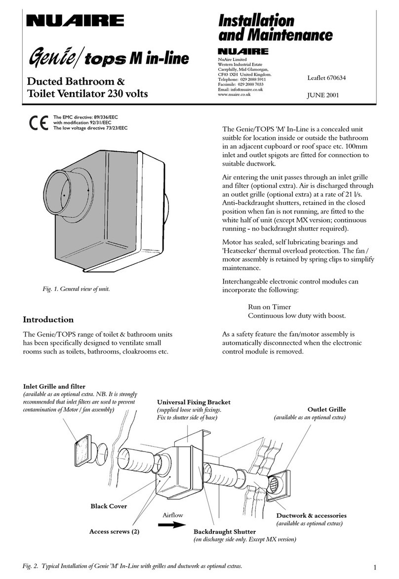
NuAire Genie/tops M in-line Instruction Manual

NuAire

NuAire Genie/tops M in-line Instruction Manual

Popular Fan manuals by other brands

GE Treviso 20314 user manual

GE

GE Treviso 20314 user manual

Canarm DPL-12 Operation instructions and parts manual

Canarm

Canarm DPL-12 Operation instructions and parts manual

Beper VE.501 use instructions

Beper

Beper VE.501 use instructions

Fanimation Involution FP4520 Series Specification sheet

Fanimation

Fanimation Involution FP4520 Series Specification sheet

Sonedas 9688463 Instruction guide

Sonedas

Sonedas 9688463 Instruction guide

Vortice VORT LETO MEV Instruction booklet

Vortice

Vortice VORT LETO MEV Instruction booklet

Vortice VORTICENT C 30/2 M Instruction booklet

Vortice

Vortice VORTICENT C 30/2 M Instruction booklet

Lasko 1844 operating manual

Lasko

Lasko 1844 operating manual

Ebmpapst G2D180-BD02-07 operating instructions

Ebmpapst

Ebmpapst G2D180-BD02-07 operating instructions

U-Line H-9818 quick start guide

U-Line

U-Line H-9818 quick start guide

NEFF I97CQS9S5 User manual and installation instructiions

NEFF

NEFF I97CQS9S5 User manual and installation instructiions

The Modern Fan Company Plum Installation instructions and owner's manual

The Modern Fan Company

The Modern Fan Company Plum Installation instructions and owner's manual

GoWISE USA Ultra Air 42" GW21102 user guide

GoWISE USA

GoWISE USA Ultra Air 42" GW21102 user guide

Be Cool BC121TU2201F manual

Be Cool

Be Cool BC121TU2201F manual

Savio FAN-01 user manual

Savio

Savio FAN-01 user manual

Honeywell Home DR65A3000 Professional installation guide

Honeywell Home

Honeywell Home DR65A3000 Professional installation guide

Envira-North EN560X0010 Design & engineering guide

Envira-North

Envira-North EN560X0010 Design & engineering guide

Bryant ERVBBSVB Product data

Bryant

Bryant ERVBBSVB Product data

manuals.online logo
manuals.online logoBrands
  • About & Mission
  • Contact us
  • Privacy Policy
  • Terms and Conditions

Copyright 2025 Manuals.Online. All Rights Reserved.