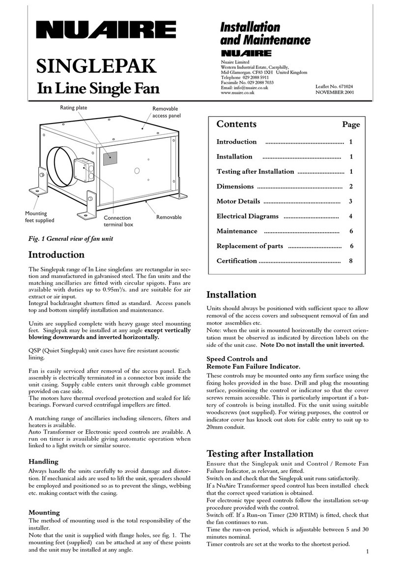
Note:
A gravity anti-backdraught shutter is used in this unit (except MX
unit). Therefore if the unit is installed in a vertical duct, the shutter
must be on top, the airflow upwards. See diagram C below.
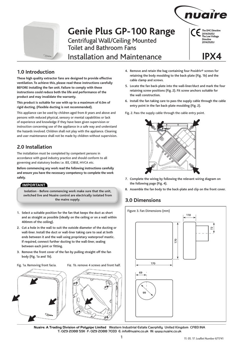
e) Feed the supply cable through the cable entry. Connect the wiring
to the internal terminal block/socket. (NB. For ease of wiring, the
internal terminal block/socket should be temporarily removed from
its position). Following connection of the supply cable, refit the terminal
block/socket. (2 screws).
f) Fit the fan assembly to the case, mating its plug fully with the
internal socket. Lock with the spring clips.
g) Fit the control module into the slider. NB. Ensure that the control
Module is fully engaged with socket. See Fig. 3.
h) Fit the other section of the flexible ducting to the inlet spigot on
the remaining (cover) half of the case. Before refitting cover switch
on the unit momentarily at the isolator and check that the green
running light is illuminated before replacing black cover and secure
with screws.
i) Test/run the unit.
Installation details for unit supplied with
pre-wired mains cable:
For Genie/TOPS 'M' units supplied pre-wired with nominal length
(1.5m) of cable install as follows:
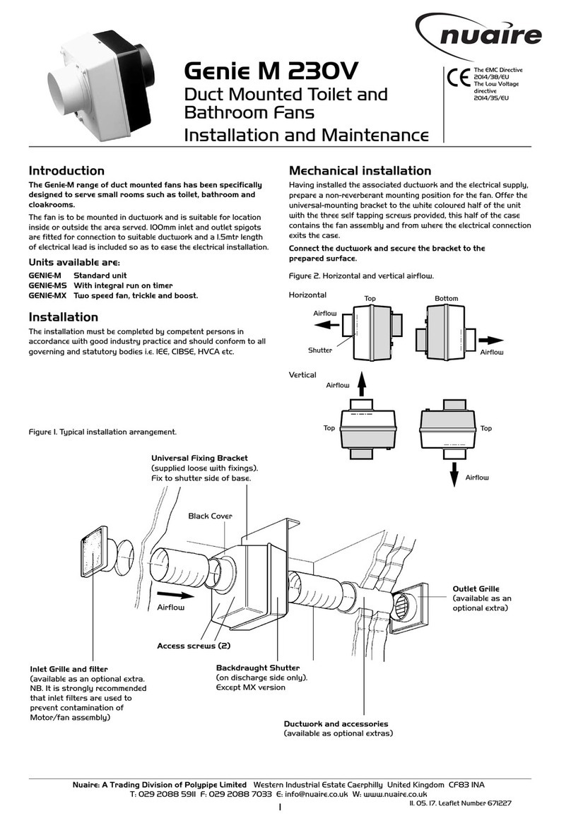
a) It is assumed that a solid non reverberant mounting position has
been prepared inside the duct passage area and the necessary ductwork
already installed with adequate clearance on the inlet side to allow
fitting of the flexible ducting supplied with the unit. It is also assumed
that the electrical connections are in position. (Typically a switched
fusible spur or equivalent to comply with the 16th Edition of the
I.E.E. wiring regulations and local Electricity Board or Bye-Law
requirements).
b) Fit the mounting bracket (supplied separate in the box) to the white
half of the case, using three self tapping screws supplied.
c) Assemble the outlet spigot to the ducting and fix the unit to a solid
non-reverberant surface using two No. 8 woodscrews through the
mounting bracket, drilling and plugging the fixing area if necessary.
d) Fit the other end of the flexible ducting to the spigot on the black
half of the case.
e) Test/run the unit.
Installation
(To be carried out by qualified personnel only)
NuAire’s Genie/TOPS 'M' range of duct mounted domestic
extract fans are designed to extract small volumes of air through
100mm dia. ducting. Extract rate 21 l/s. Inlet is through a 100mm
spigot located on the front of the unit.
Units can be fitted with a selection of controls which enable them
to be linked to light switches, either directly or through run-on
circuits.
a) It is assumed that a solid non reverberant mounting position has
been prepared inside the duct passage area and the necessary
ductwork already installed. It is also assumed that the electrical
connections are in position. (Typically a switched fusible spur or
equivalent to comply with the 16th Edition of the I.E.E. wiring
regulations and local Electricity Board or Bye-Law requirements).
b) Separate the two halves of the unit by removing the screws (2
off) on the black half of the unit. Detach control module from
slider and release the two internal clips. Then remove the fan
unit. See Fig. 3.
c) Fit the mounting bracket (supplied with unit) to the half of the
case containing the wiring socket, using three self tapping screws
supplied.
d) Assemble the outlet spigot to the ducting and fix the casing to
a solid non-reverberant surface using two No.8 woodscrews
through the mounting bracket, drilling and plugging the fixing
area if necessary.
Top
Bottom
Shutter
Air flow
✓
Bottom
Top
Air flow
Shutter
✓
Top Bottom
Air flow
Shutter Vertical
✓
Air flow
Shutter
Top
Horizontal
Fig. 5. Recommended Installation.
2
Fig 4. Universal Mounting bracket.
A. B.
C. D.
Fig. 3. Electronic control module and Fan/Motor assembly.
✗


