NuAire HIAQM User manual

1
16. 04. 21. Document Number 671965
Nuaire | Western Industrial Estate | Caerphilly | CF83 1NA | nuaire.co.uk
HIAQM
Haven Indoor Air Quality Filter Module
Installation Manual
1.0 SAFETY INFORMATION
• The provision of the electrical supply and the connection of the unit to the electrical supply must
be carried out by a qualified electrician.
• Isolate from power supply before removing any covers. During installation / maintenance ensure
all covers are fitted before switching on the mains supply.
• All-pole disconnection from the mains as shown in the wiring diagram must be incorporated
within the fixed wiring and shall have a minimum contact separation of 3mm in accordance with
latest edition of the wiring regulations.
• Ducting must be securely fixed with screws to the spigot to prevent access to live parts. Duct
runs terminating close to the fan must be adequately protected by suitable guards.
• This appliance should not be used by children or persons with reduced physical, sensory or
mental capabilities or lack of experience and knowledge, unless they have been given supervision
or instruction concerning the safe use of the appliance by a person responsible for their safety.
Children shall not play with the appliance. Cleaning and user maintenance shall not be carried
out by children.
• Carbon filters/pellets are not to be ingested, ensure hands are thoroughly washed after handling.
1.1 Symbols
GENERAL WARNING
Signifies a general warning regarding hazard specified by supplementary information.
ELECTRIC SHOCK
This unit must be completely electrically isolated before any panels are removed. Check
mains supply and control connections.
REFER TO INSTRUCTION MANUAL
Read and understand the installation and maintenance manual before installing,
operating or maintaining this product.
1.2 Important Information
This manual contains important information on the safe and
appropriate assembly, transport, commissioning, operation,
maintenance, disassembly and simple troubleshooting of the product.
While the product has been manufactured according to the accepted
rules of current technology, there is still a danger of personal injury or
damage to equipment if the following general safety instructions and
the warnings contained in these instructions are not complied with.
•Read these instructions completely and thoroughly before
working with the product.
•Keep these instructions in a location where they are accessible
to all users at all times.
•Always include the operating instructions when you pass the
product on to third parties.
1.3 Personal Protective Equipment
The following minimum Personal Protective Equipment (PPE) is
recommended when interacting with Nuaire product:
•Protective Steel Toed Shoes - when handling heavy objects.
•Full Finger Gloves (Marigold PU800 or equivalent) - when
handling sheet metal components.
•Semi Fingerless Gloves (Marigold PU3000 3DO or equivalent)
- when conducting light work on the unit requiring tactile
dexterity.
•Safety Glasses - when conducting any cleaning/cutting operation
or exchanging filters.
•Reusable Half Mask Respirators - when replacing filters which
have been in contact with normal room or environmental air.
Nuaire would always recommend a site specific risk assessment by a
competent person to determine if any additional PPE is required.

2
16. 04. 21. Document Number 671965
Nuaire | Western Industrial Estate | Caerphilly | CF83 1NA | nuaire.co.uk
HIAQMInstallation Manual
2.0 INTRODUCTION
The Haven IAQ Module range of ancillaries has been specially designed
to complement the existing commercial range of XBC+ units as well as
providing a general function of high grade filtration to any commercial
ventilation units which require it. The unit shall be manufactured
from Alu-zinc with double skin panels filled with insulation to provide
thermal and acoustic barriers. The units will come as standard with
pressure monitoring for the filtration and give a relay output for alarm
signalling when a pre-determined pressure value is exceeded. The
units will be available with different access options (Bottom or Side
access) as well as weatherproofing and coastal varieties depending on
installation location. The unit is unhanded with different operations
to suit it for different installations available in this literature. Further
information regarding performance and specifications for the
equipment may be obtained from our technical literature, and/or
project specific documentation.
2.1 Code Description:
1 - 2 - 3 - 4 - 5 - 6 7
HIAQM - 015 - S -A-A-1 W
1. Range: HIAQM = Haven Indoor Air
Quality Filter Module
2. Reference Flowrate: 015 = 0.15m3/s
025 = 0.26m3/s
045 = 0.35m3/s
055 = 0.48m3/s
065 = 0.58m3/s
3. Access Type: S = Side Access
B = Bottom Access
4. Primary Stage Filter: A = G4 / ISO Coarse
(Panel) B = M5 / PM10 50%
C = M6 / PM2.5 50%
D = F7 / PM1 50%
E = F8 / PM1 70%
F = F9 / PM1 80%
H = No Filter
5. Secondary Stage Filter: A= G4 / ISO Coarse
(Bag) B= M5 / PM10 50%
C = M6 / PM2.5 50%
D= F7 / PM1 50%
E= F8 / PM1 70%
F= F9 / PM1 80%
G= Rigid Carbon Panel Unit
(RCP)
6. Unit Finish: 1 = Standard
4 = Coastal (C4*)
7. Unit Roof: 1 = Standard Unit (No Roof)
W = Twin Pitched Roof (Factory
Fitted)
* This units coastal finish has been designed to withstand an External
C4 Atmospheric Corrosivity Category as per BS EN ISO 12944-2:2017
providing that it is installed and maintained as per the manufacturer’s
instructions and general Warranty Guidance Notes found in our
conditions of sale.
2.2 Dimensions & Weight
2.2.1 Standard Side Access Unit (e.g. HIAQM-015-S-A-A-11)
1 Standard Side Access Unit Dimensions
2.2.2 Standard Bottom Access Unit (e.g. HIAQM-015-B-A-A-11)
2 Standard Bottom Access Unit Dimensions
Unit Size Side / Bottom Hanging
Bracket Flange
Connector Length Side
Access
Units
Bottom
Access
Unit
A B C D E F G H J J
IAQM-015 890 665 259 755 690 351 218 1010 728 709
IAQM-025 990 809 339 855 830 481 298 1110 869 849
IAQM-045 990 885 399 855 907 536 358 1110 945 925
IAQM-055 990 1068 469 855 1090 592 428 1110 1128 1108
IAQM-065 890 1068 622 755 1090 592 578 1010 1128 1108
2.2.3 Twin Pitched Roof Unit (e.g. HIAQM-015-S-A-A-1W)
3 Twin Pitched Roof Unit Dimensions
Unit Size Side / Bottom Flange
Connector Length Width
A B C F G H J
IAQM-015 902 695 334 351 218 1010 729
IAQM-025 1002 839 424 481 298 1110 870
IAQM-045 1002 915 489 536 358 1110 946
IAQM-055 1002 1098 574 592 428 1110 1129
IAQM-065 902 1098 727 592 578 1010 1129

3
16. 04. 21. Document Number 671965
Nuaire | Western Industrial Estate | Caerphilly | CF83 1NA | nuaire.co.uk
HIAQMInstallation Manual
2.3 Delivery of Equipment
2.3.1 Receipt of Equipment
All equipment is inspected prior to despatch and leaves the factory in
good condition. Upon receipt of the equipment an inspection should be
made and any damage indicated on the delivery note.
Particulars of damage and/or incomplete delivery should be endorsed
by the driver delivering the goods before offloading by the purchaser.
No responsibility will be accepted for damage sustained during the
offloading from the vehicle or on the site thereafter. All claims for
damage and/or incomplete delivery must be reported to Nuaire within
two days of receipt of the equipment following guidance in our terms &
conditions of sale.
2.3.2 Offloading and Handling
The weight of the unit modules and palletised items is displayed on
the unit rating plate or on the packaging. Some of the modules have an
uneven weight distribution, and this will be indicated by labelling where
appropriate. Ensure that lifting and handling equipment is adequately
rated. Offloading and positioning of the equipment is the responsibility
of the purchaser.
Spreaders should be used when lifting with slings to avoid damage
to the casings. Care must be taken to ensure that slings are correctly
positioned to avoid crushing and twisting of the unit castings.
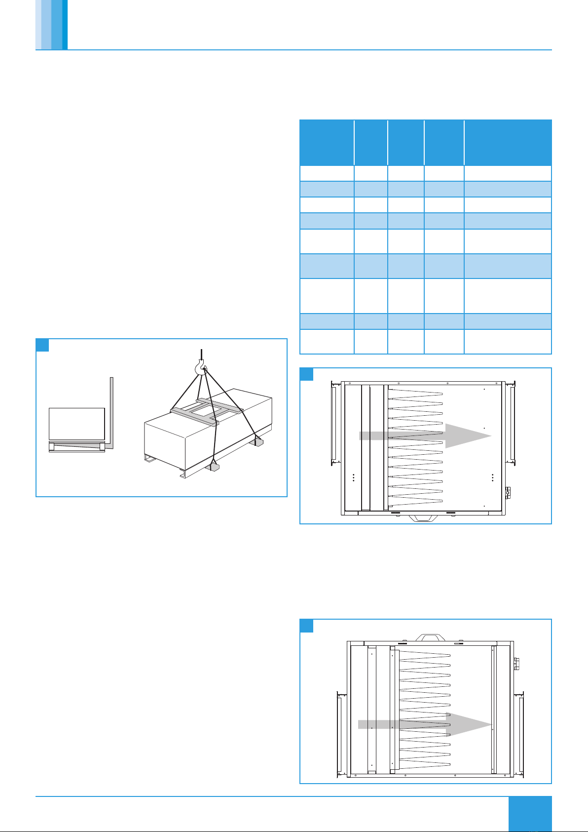
4 Unit Lifting
Palletised.
Slings via spreaders fitted to unit with base frame.
3.0 MECHANICAL INSTALLATION
Installation of the IAQ modules, including all external services and
controls should be in accordance with the appropriate authority and
MUST conform to all governing regulations e.g. CDM, CIBSE, IEE, and in
strict accordance with the applicable Building Regulations. These units
may only be mounted horizontally.
The correct installation position for the units shall be decided with due
regard to access and maintenance requirements, and the objective of
minimising the system ductwork resistance.
The units are heavy, and should be mounted using the fixing brackets
supplied or other suitable methods of support. The supporting structure
must be assessed for structural suitability.
The recommended installation method is to use standard Unistrut
channel secured to the slab / steelwork above the unit.
Four suitable drop rods should be secured to the Unistrut channel and
extended to be fixed to the unit’s four mounting brackets (two each
side of the unit), or to other horizontal supports by others where wider
load distribution is required.
3.1 IAQM Layout Modifications
Depending on the installation requirements of the IAQM unit (e.g.
location, orientation, model variant, etc.), onsite modifications of the
module may be needed. Refer to the table provided for modification
requirements.
Fan Unit
Attachment
Method
Access
Type
HIAQM
Roof
XBC
Unit
Handing
Required IAQM
Layout Modifications
Ducted Side No N/A None.
Ducted Side Yes N/A None.
Ducted Bottom No N/A None.
Close Coupled Side No Left Attach XBC Flange.
Close Coupled Side No Right Attach XBC Flange,
Roll IAQM Unit.
Close Coupled Side Yes Left Attach XBC Flange,
Relocate IAQM Roof,
Close Coupled Side Yes Right
Attach XBC Flange,
Roll IAQM Unit,
Relocate IAQM Roof.
Close Coupled Bottom No Left Attach XBC Flange.
Close Coupled Bottom No Right Switch Spigot Plates,
Attach XBC Flange.
Side Access IAQM Modified For Use With Left Handed XBC’s
AIRFLOW
5 Standard IAQM Layout
3.1.1 Switching Spigot Plates
If bottom access IAQM unit is to be close coupled to a right hand
configuration XBC unit, the IAQM unit inlet and outlet spigot plates
must be switched to ensure XBC ducting paths are clear. Detach both
IAQM spigot plates by removing the bolts securing the plate to the
IAQM unit. Exchange the inlet and outlet spigot plates and reattach to
the IAQM using the same bolts and fixing points.
Side Access IAQM Modified For Use With Left Handed XBC’s Side Access IAQM For Use With Right Handed XBC’s
AIRFLOW
6 Modified (Spigot Plates Switched) IAQM Layout

4
16. 04. 21. Document Number 671965
Nuaire | Western Industrial Estate | Caerphilly | CF83 1NA | nuaire.co.uk
HIAQMInstallation Manual
Standalone IAQM with RoofModified IAQM With Roof Close Coupled To XBC with Roof
AIRFLOW
Inlet Spigot Outlet Spigot
Roof Fixing Points
Roof / Mounting Points
Outlet Spigot
9 Standard Ducted IAQM With Roof
Modified IAQM With Roof Close Coupled To XBC with Roof
AIRFLOW
Roof Fixing Points
Roof / Mounting Points
Inlet Spigot Outlet Spigot
10 Close Coupled IAQM With Modified (Relocated) Roof
3.2 Dirty Filter Pressure Switch
Isolate from power supply before removing any covers. During
installation / maintenance ensure all covers are fitted before
switching on the mains supply.
Replacement Pressure switches are available if needed (HAVEN-PDIFF).
11 Dirty Filter Switch Details
(3x)
2
5.4
1
1
p
>
2
3
N
3
Max: ~5(2) A 250V
ø 8-10 mm
+
-
+ -
3.2.1 Dirty Filter Pressure Switch Wiring
The cable gland is designed for cables with alternative sheath diameters
of 8 - 10 mm. Only use these sizes, otherwise the screw cable
connection cannot seal adequately. The connections are intended for
6.3mm crimp-type sockets.
•Remove switch cover.
•Wire the main unit to the terminal block within the switch as per
the below wiring diagrams (Figure 12) ensuring the feed line is
fused to suit Max 1.5A / 250 Vac.
3.1.2 Attaching XBC Flange
To aid in installation where IAQM units are to be close coupled to a
matching size XBC unit, the double (Supply & Extract) flange connector
of the XBC unit should be removed from the XBC and fitted to the
IAQM unit’s inlet along with the extract leg ducting. The full assembly
of IAQM unit, XBC flange connector and extract ducting can then be
raised and connected to the XBC unit. For further details see "Flange
Connector Dimensions (mm)" section, located in XBC+ installation
manual provided with XBC+ units.
7 HIAQM Connected to XBC+ Unit
3.1.3 Rolling IAQM Unit
If a side access IAQM unit is to be close coupled to a right hand
configuration XBC unit, roll the IAQM unit 180° to ensure XBC ducting
paths are clear.
Where a roof is supplied with the IAQM the roof should be removed
by unscrewing the 4x roof mounting points (2x M8 hex bolts) before
rolling the unit and reattaching the roof using the same 4 roof
mounting points.
Where an IAQM has no roof, the 4x mounting brackets provided can
be also be removed (2x M8 hex bolts) and reattached according to the
required mounting method if needed.
Roll IAQM 180°
I
n
le
t
A
i
r
fl
o
w
8 Handling IAQM Unit
3.1.4 Relocating IAQM Roof
Due to the XBC roof overhang, an IAQM with roof cannot be close
coupled to an XBC unit with roof without relocating the IAQM roof
prior to installation.
Unscrew the M8 hex bolts attaching the IAQM roof to the 1st and 2nd
roof fixing points. Slide the IAQM roof away from the IAQM inlet and
utilize the 2nd and 3rd roof fixing point to reattach the IAQM roof.

5
16. 04. 21. Document Number 671965
Nuaire | Western Industrial Estate | Caerphilly | CF83 1NA | nuaire.co.uk
HIAQMInstallation Manual
•Refit switch cover.
Schematic Diagram
Pressure Sensor Internals
2 - NO
3 - C
1 - NC
3 - C Contacts 2 - NO
when the difference between
positive & negative pressure
is equal to the set pressure.
Customer 240 V
Connection
Customer 240V
Connection
Internal Connection
Customer Connection
*Note 1: NC has been
blanked off.
*Note 2: Pressure setting
of 125Pa above clean filter
pressure is recommended.
*Note 3: If a different
arrangement is required,
then the internal LED con-
nections can be removed.
240 V
Indicator
240 V
Indicator
Sensor Diagram
2 - NO
1 - NC
*Note 2
*Note 3
*Note 1
Differential
Pressure
Setting
3 - C
12 Dirty Filter Switch Wiring
3.2.2 Setting Dirty Filter Switch Pressure
Nuaire recommend the pressure switch be set to trigger when the
filters experience a 125 Pa increase above the clean filter resistance for
the largest commissioned airflow rate. Use the adjustment dial to set
the pressure at which the switch will trip. When the pressure falls below
this set value, the switch returns to its resting position.
4.0 MAINTENANCE
It is important that maintenance checks are recorded and that the
schedule is always adhered to, in all cases, the previous report should
be referred to.
4.1 Carbon Filter Maintenance
After a period of time, activated carbon in filter cells will become
saturated by odour, gas and chemical vapour contaminants and will
require replacement in order to maintain the filtration efficiency of the
carbon filter. HIAQM Carbon Filters have a lifespan of 2 years under
normal conditions. However, under certain circumstances, such as
highly polluted air, carbon filters may need to be replaced on a more
frequent basis. Contact Nuaire for accurate assessments of carbon filter
lifespans.
4.2 Routine Maintenance
•Clean all areas of unit and treat any areas of corrosion.
•Check all access doors for leakage and if necessary locks should be
adjusted and any replacement gasket materials should be replaced
as required.
4.3 Every 3 Months
•Check filters and change/clean if required, failure to do so may
impair the performance and energy efficiency of this unit.
4.4 Annually
•Thoroughly inspect the unit and its components for corrosion,
acting immediately to treat/restore any damaged areas.
4.5 Replacement Filters
To check the filter type within a unit refer to the module product label.
Replacement filters can be purchased direct from Nuaire using the
below code format.
1 - 2 - 3 4 - 5
HIAQM - 015 - 1 D-FILTER
1. Range: HIAQM = Haven Indoor Air Quality
Filter Module
2. Reference Flowrate: 015 = 0.15m3/s
025 = 0.26m3/s
045 = 0.35m3/s
055 = 0.48m3/s
065 = 0.58m3/s
3. Filter Position: 1 = Primary Panel Filter
2 = Secondary Bag Filter
4. Filter Grade: A= G4 / ISO Coarse
B= M5 / PM10 50%
C= M6 / PM2.5 50%
D= F7 / PM1 50%
E= F8 / PM1 70%
F= F9 / PM1 80%
G= Rigid Carbon Panel Unit
(RCP)
For reference on the filter type required please refer to the module
product label e.g. The codes required to order both filters of a
HIAQM-025-S-D-G-11 would be:
HIAQM-015-1D-FILTER
HIAQM-015-2G-FILTER
5.0 WARRANTY
The 5 year warranty starts from the day of delivery and includes parts
and labour for the first year. The remaining period covers replacement
parts only (replacement filters not included).
This warranty is void if the equipment is modified without
authorisation, is incorrectly applied, misused, disassembled, or not
installed, commissioned and maintained in accordance with the details
contained in this manual and general good practice.
The product warranty applies to the UK mainland and in accordance
with Clause 14 of our Conditions of Sale. Customers purchasing from
outside of the UK should contact Nuaire International Sales office for
further details.
Failure to maintain the unit as recommended will invalidate the

6
16. 04. 21. Document Number 671965
Nuaire | Western Industrial Estate | Caerphilly | CF83 1NA | nuaire.co.uk
HIAQMInstallation Manual
warranty.
6.0 END-OF-LIFE AND RECYCLING
Where possible Nuaire use components which can be largely recycled
when the product reaches its end-of-life:
•Fans, motors, controls, actuators, cabling and other electrical
components can be segregated into WEEE recycling streams.
•Sheet metal parts, aluminium extrusion, heating/cooling coils and
other metallic items can be segregated and fully recycled.
•EPP, plastic ducting, nylon corner pieces, plastic heat exchangers,
packaging material and other plastic components can be
segregated into mixed plastic and widely recycled.
•Cardboard packaging, wood, used filters and other paper
components can be largely recycled or fully processed in energy
from waste centres.
•Remaining Items can be further segregated and processed in
accordance with the zero waste hierarchy. Please call After Sales
Support for further information on items not listed above.
Ensure that Nuaire product is made safe from any electrical / water
/ refrigerant supplies before dismantling commences. This work
should only be undertaken by a qualified person in accordance with
local authority regulations and guidelines, taking into account all
site based risks.
7.0 AFTER SALES AND REPLACEMENT PARTS
For technical assistance or further product information, including spare
parts and replacement components, please contact the After Sales
Department.
If ordering spares please quote the serial number of the unit together
with the part number, if the part number is not known please give a full
description of the part required. The serial number will be found on the
identification plate attached to the unit casing.
Telephone 02920 858 400
aftersales@nuaire.co.uk

7
16. 04. 21. Document Number 671965
Nuaire | Western Industrial Estate | Caerphilly | CF83 1NA | nuaire.co.uk
HIAQMInstallation Manual
NOTES

8
16. 04. 21. Document Number 671965
Nuaire | Western Industrial Estate | Caerphilly | CF83 1NA | nuaire.co.uk
HIAQMInstallation Manual
NOTES
Table of contents
Other NuAire Water Filtration System manuals
Popular Water Filtration System manuals by other brands

Pontec
Pontec PondoRell 3000 operating instructions

Doughboy
Doughboy Media Master 1600 owner's guide

Nimbus Water Systems
Nimbus Water Systems CS-2 user manual

Fiap
Fiap Turbo Active manual

ScaleSolver
ScaleSolver 97SLP Installation, operation and maintanance manual

Beckett
Beckett Pond Filter RFPCOMBO Specifications

T.I.P.
T.I.P. WDF 10000 owner's manual

Eaton
Eaton EDSF 1201-15001 Manual and maintenance instructions

Pureway
Pureway ECO II Assembly, operation and maintenance instructions

BWT
BWT Woda Pure Energy Installation and operating manual

Machinery World
Machinery World Tetra Centri A 614HGV-14C Service & Maintenance

Rainfresh
Rainfresh R519 Installation & maintenance instructions