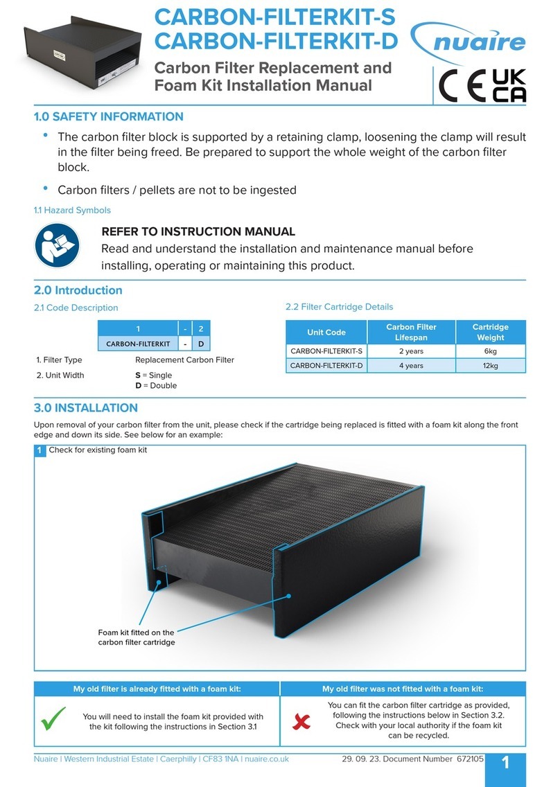
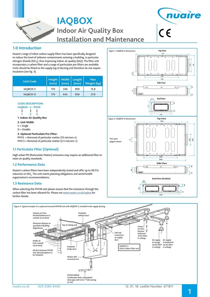
NuAire NOXMASTER User manual

1
nuaire.co.uk 029 2085 8400 19. 02. 19. Document Number 671881
The EMC Directive
2014/30/EU
The Low Voltage
Directive
2014/35/EU
PIV with Carbon Filtration
Installation Manual
1.0 SAFETY INFORMATION
•The provision of the electrical supply and the connection of the NOXMASTER unit to the mains
must be carried out by a qualified electrician.
•For installation and maintenance isolate from power supply before removing any covers.
•All-pole disconnection from the mains as shown in the wiring diagram must be incorporated
within the fixed wiring and shall have a minimum contact separation of 3mm in accordance with
latest edition of the wiring regulations.
•In order to avoid a hazard due to inadvertent resetting of the thermal cut-out, this appliance must
not be supplied through an external switching device, such as a timer, or connected to a circuit
that is regularly switched on and off by the utility.
•The fan unit is supplied with a fused spur. The three core mains cable from the fan unit should
be connected to a fixed wiring installation, via the spur, in accordance with current IEE wiring
regulations.
•If the mains supply cord to the PSU is damaged, it must be replaced by the manufacturer, its
service agent or similarly qualified persons in order to avoid a hazard.
•The heater unit must be connected to the ceiling vent and fan unit using the 3 looms that
protrude from the heater module.
•The unit must be situated in a dry environment that avoids dripping water and installed fully level
in the horizontal plane.
•It is important to ensure that the diffuser is NOT placed within 1 metre of a smoke alarm. If the
diffuser cannot be repositioned, two sides of the diffuser must be closed off using the air dams
supplied to encourage the air through the remaining open sides that faces at least 1.5 metres of
unobstructed area away from the smoke alarm sensor.
•If the unit is required to switch off in the event of smoke/CO detection, alarms are available with
separate relay bases from 3rd party companies. This is a mandatory requirement for all units
installed in a 3 Storey property.
•The flexible duct (maximum length 2m) is connected to the base unit by inserting the duct over
the outlet duct and held in place using the supplied cable tie. Fix the duct in place by drilling
through the duct into the spigot (at the 2 O'clock and 10 O'clock position) and screwing together.
Finally secure the duct with a cable tie fitted between the screws and outlet face of the unit.
•Ducting must be securely fixed with screws to the spigot to prevent access to live parts.
•When installing the duct to the heater unit, insert the duct over the back of the heater, over the
protruding screw heads (3mm from the face of the duct) and fasten the cable tie below the screws.
This ensures that the duct will be held on securely, check all duct joints are air tight.
•Appropriate PPE (Personal Protective Equipment) should be worn during maintenance. Precautions
may also be needed to protect the surrounding area from excess carbon residue.
•Carbon filters/pellets are not to be ingested, ensure hands are thoroughly washed after handling.
•Precautions must be taken to avoid the back-flow of gases into the room from the open flue of gas
or other fuel-burning appliances.

2
nuaire.co.uk 029 2085 8400 19. 02. 19. Document Number 671881
Installation Manual NOXMASTER - PIV with Carbon Filtration
•This appliance should not be used by children or persons with reduced physical, sensory or
mental capabilities or lack of experience and knowledge, unless they have been given supervision
or instruction concerning the safe use of the appliance by a person responsible for their safety.
Children shall not play with the appliance. Cleaning and user maintenance shall not be carried out
by children.
or instruction concerning use of the appliance in a safe way and
understand the hazards involved. Children shall not play with the
appliance. Cleaning and user maintenance shall not be carried out by
children without supervision.
Precautions must be taken to avoid the back-flow of gases into the
room from the open flue of gas or other fuel-burning appliances.
Means for disconnection must be incorporated in the fixed wiring as
shown in the wiring diagram in accordance with IEE wiring or national
wiring rules.
CAUTION: In order to avoid a hazard due to inadvertent resetting of
the thermal cut-out, this appliance must not be supplied through an
external switching device, such as a timer, or connected to a circuit that
is regularly switched on and off by the utility.
4.1 Loft Inspection
Ensure that the loft has adequate ventilation. There may be occasions
where a loft is so well sealed that additional ventilation may have to be
provided by the owner/occupier.
Ensure that all water tanks are covered and sealed.
Check that all water pipes are lagged.
Check the area of the installation that beams are flat and level and are
capable of supporting the total weight of the unit.
Ensure the insulation is not proud of the beams. If insulation is prouder
than the beams, alternative arrangements to provide a flat surface
above the insulation may be required. Do not install the unit with
insulation contacting the underside of the unit.
Ensure that extract fans are discharging to outside, not into the loft.
Check that the loft hatch is tightly sealed.
Ensure that all ceiling holes are sealed i.e. ceiling light fittings etc. A
visual inspection of any flues or chimneys for leakage in the loft should
be carried out by the installer.
If any leakage points are found, or if there is any doubt at all, then the
installer should advise the house owner/provider as soon as possible
and seek instruction from them before proceeding with the installation.
2.0 INTRODUCTION
Nuaire’s NOXMASTER range has been specifically designed to improve
the indoor air quality and provide a whole home ventilation solution.
Combining the principles of positive input ventilation (PIV) and carbon
filter technology the unit provides cleaner, fresher, filtered air into the
a dwelling at a continuous rate, encouraging the movement of air from
inside to outside. To achieve this, the unit is mounted in the loft space
and draws air from either the loft space or ducted supply from the
exterior of the house (dependant on the operating temperatures).
Unlike conventional PIV units, NOXMASTER units are fitted with
dual inlets, which automatically select the air source based on the
surrounding temperature:
•If the loft temperature is below the set point (recommended 24°C)
then the unit will take fresh air from the loft space.
•If the loft temperature is above the set point (recommended
24°C) then cooler fresh air will be taken from outside the dwelling
through a ducted supply (if fitted).
To improve the efficiency of the NOXMASTER unit, it is fitted with a
carbon filter bypass. The bypass is controlled on a time basis and is
programmed to operate during times of low pollution (e.g. night time
when air pollution is lower).
3.0 PACKAGING AND DELIVERY
Please ensure you have the ability to handle and store this unit, as
it may be delivered in three individual boxes strapped to a pallet as
shown below.
4.0 INSTALLATION
Successful operation of the fan depends entirely upon the unit being
installed strictly in accordance with these instructions. Please read
through this guide in its entirety before commencing installation and
follow step by step to ensure a satisfactory completion. Whilst the
installation of the NOXMASTER unit may be achieved by suitable
persons, the provision of the electrical supply and the connection of the
unit to the mains must be carried out by a qualified electrician.
Warning: Isolate from power supply before removing any covers. During
installation/ maintenance ensure all covers are fitted before switching
on the mains supply.
This appliance can be used by children aged from 8 years and above
and persons with reduced physical, sensory or mental capabilities or
lack of experience and knowledge if they have been given supervision
POD A (Carbon Filter)
Weight: 22Kg
POD B (Blower)
POD B (Blower)
Weight: 12Kg
AIRFLOW
1371
1381
Loft Intake
787
433
527
Ducted Intake
(Ø150mm Spigot supplied)
119
Ø201
24
319
200
102
168
197
500
Figure 1. Unit Layout & Dimensions Figure 2. Palleted DImensions
A
B
C
BOX 2
BOX 1
BOX 3
Item Dimensions (mm) Weight
(kg)
A B C
Euro Pallet 900 1200 800
BOX 1 981 585 362 22
BOX 2 685 585 362 12
BOX 3 535 230 340 6

3
nuaire.co.uk 029 2085 8400 19. 02. 19. Document Number 671881
Installation Manual NOXMASTER - PIV with Carbon Filtration
Ceiling Vent
Two Air Dams (supplied) can t on any of the diuser sides to guide
airow away from a smoke detector and/or obstructions as required.
Diuser Cap
Airow
Airow
4.2 Diffuser Installation
4.2.1 Positioning the Diffuser
The diffuser has a unique air throw pattern and it is essential that it is
located correctly in the central hallway in single storey properties or in
the ceiling of the top floor landing on two or more storey dwellings.
The diffuser discharges air evenly in all directions along the underside of
the ceiling.
Note: SMOKE ALARMS -It is also important to ensure that the
diffuser is NOT placed within 1 metre of a smoke alarm.
If the diffuser cannot be repositioned, two sides of the diffuser must
be closed off using the air dams supplied to encourage the air through
the remaining open sides that faces at least 1.5 metres of unobstructed
area away from the smoke alarm sensor.
4.2.2 Fitting the Air Dams (if Required)
Air dams should be fitted where needed in order to alter the direction
of airflow. Two air dams are supplied and will fit on any of the diffuser
sides to guide airflow away from a smoke detector and/or obstructions.
4.2.3 Fitting the Ceiling Diffuser
To install the diffuser, use the tear-out template from the lid of the unit
packaging and trace the shape onto the ceiling between two convenient
The heater unit must be connected to the ceiling vent and fan unit
using the 3 looms that protrude from the heater module. Connect
the ceiling vent control loom to the circuit board on the ceiling vent
and insert the heater module into the ceiling vent. Connect the
interconnecting loom into the control output and the mains power
loom into the heater output (Figure 4). The flexible duct (maximum
length 2m) is connected to the base unit by inserting the duct over the
outlet duct and held in place using the supplied cable tie.
Finally when installing the duct to the heater unit, insert the duct over
the back of the heater, over the protruding screw heads (3mm from the
face of the duct) and fasten the cable tie below the screws. This ensures
that the duct will be held on securely, check all duct joints are air tight.
FURTHER MEASURES MAY BE REQUIRED.
4.3 NOXMASTER Installation
4.3.1 Connecting Sections
The unit is delivered in two sections, pod A (Carbon filter) and pod B
(blower) which require connecting, refer to the layout drawing (Figure
1).
•Remove the nut and bolt from the black connectors on either side
of the unit and store safely to one side.
•Position the pods 1 – 1.5M away from the desired location of
the ceiling vent. Align the two pods with both spigots facing
out, leaving a space between the pods to make the electrical
connection (Figure 5).
•Release the free end of the fly lead from pod B and align the flats
on the male connectors with the flats on the fixed connector in
pod A. Push the connectors together until the outer clips have fully
engaged and the connection is secure.
•Pull the pods together and re-insert the nut and bolt back into
the black connectors. Tighten the connectors evenly, when fully
tightened ensure the foam gasket has been evenly compressed.
4.3.2 Fitting the NOXMASTER
Connect the two ‘L’ shape fixing brackets to the short sides of the unit
with the M5 screws (provided), then lower the unit with the “L” shape
fixing brackets attached, onto the joists. Mark 4 holes through the
brackets so that the holes will be centrally positioned over a joist.
Locate anti-vibration mounts (supplied) above and below each bracket
fixing joint hole and, using the fixings provided, fix the unit to the joists.
Note: Do not overtighten the fixings.
Connect the flexible duct (maximum length 2m) to the blower unit
by placing the duct over the spigot. Secure the duct in place by drilling
through the duct and spigot (at the 2 O'clock and 10 O'clock position)
and securing with screws (provided). Finally secure the duct to the
heater/ceiling diffuser. Secure with a with a cable tie fitted between the
screws and outlet face of the unit. To connect to the ceiling vent place
the duct over the vent and secure with cable tie. Ensure all duct joints
are airtight.
Please note: The flexible ducting should NOT be installed
in a compressive state, as this will negatively impact on the
performance of the unit.
Figure 3. CeilingDiffuser
joists. The shape is elliptical to allow space for the PCB of the controls
and this should be positioned for ease of access (i.e. NOT facing over
a stairwell). Once the shape has been cut out, position the ceiling vent
and secure it in place using the 4 screws and plugs provided. After
fitting, the fan unit must be connected to the diffuser using the loom
provided. The connectors are located on the rear of the ceiling vent and
the side of the POD B below the controls.
Finally, attach the diffuser cap to the frame using the four built-in, press
on clips provided.
4.2.4 Fitting the Heater (if Applicable)
IMPORTANT
In the event of an ESD to the back of the control PCB on the
diffuser the heater may switch off. The heater can be switched
back on by pressing the button in the normal way for enabling
the heater. Care therefore should be taken not to touch the
back of the PCB during installation/commissioning.
Speed Setting Minimum distance of diffuser from wall
1 100mm
2 155mm
3 400mm
4 625mm
5 850mm
6 1000mm
IMPORTANT
The unit must be situated in a dry environment that avoids
dripping water and installed fully level in the horizontal plane.

4
nuaire.co.uk 029 2085 8400 19. 02. 19. Document Number 671881
Installation Manual NOXMASTER - PIV with Carbon Filtration
5.0 ELECTRICAL CONNECTION
5.1 Electrical Details
Voltage:
230V 1ph 50Hz
IMPORTANT
The fan unit is also supplied with a fused spur. The three core
mains cable from the unit should be connected to a fixed
wiring installation, via the spur, in accordance with current IEE
wiring regulations.
5.2 Wiring Diagrams
5.2.1 NOXMASTER (All Versions Without Heater)
1A Fused Spur
(Supplied)
2 Pole Isolator
(By Others)
MAINS
230V
50Hz N
L
Blue
Brown
Supply cord
from unit
Green/yellow
IMPORTANT
The electrical connection of the unit must be carried out by
a qualified electrician.
For good EMC engineering practice, the power supply output
cable and any sensor cables should not be placed within
50mm of other cables or each other.
4.3.3 Dual Inlets
The unit features a dual inlet which automatically selects the air source
based on the surrounding temperature. To utilise this feature, the
circular guard needs to be knocked out and the supplied spigot fitted
(ensure the lose guard is removed from the unit). If ducted air supply is
not being used, do not knock out guard.
•Fix the required spigot to the unit with the screws provided and
seal with silicone to eliminate air leakage.
•Duct to the outside using ridged ducting.
Spigot
Guard - Punched
out and removed
150mm inlet
duct to outside
Soffit grille (Part No. 775229) fixes over rectangular
ducting which has been pulled through the rectangular
hole (220mm X 80mm) cut in soffit and folded flat up
against the surface of the soffit.
Note that a minimum soffit width of 130mm is required.
Form end of
rectangular ducting
to fit connector
and secure using
dynotie connector.
150mm dia.
insulated ducting
connected to unit
spigot using
dynotie connector
(Part No. FLDI150).
220mm x 90mm flexible
PVC Rectangular ducting
(Part No. PVC933WH).
Note: this duct should
be kept as short as
possible.
Circular duct connector
(Part No. RDC150).
150mm dia. insulated ducting
connected to unit spigot using
dynotie connector
(Part No. FLDI150).
150mm dia. pipe
(Part No. PVC130-6WH).
Insulated duct formed over pipe
and sealed with dynotie connector.
199 x 215 x 20mm
white plastic wall grille
(Part No. PVC604WH).
Figure 7. Fitting Dual Inlets
Figure 8. Soffit Installation
Figure 9. Wall Installation
Ceiling
Joist
Metal
Mounting
Bracket
A.V.
Mount
A.V.
Mount
Washer 3” Woodscrew
50mm
Min.
12mm
Clearance
Hole
Control Output
Time Clock (controls bypass damper)
Thermostat (controls intake damper)
Heater Output
Figure 4. Anti-Vibration Mount Installation
Figure 5. NOXMASTER-HEAT Installation
Figure 6. NOXMASTER-HEAT Installation

5
nuaire.co.uk 029 2085 8400 19. 02. 19. Document Number 671881
Installation Manual NOXMASTER - PIV with Carbon Filtration
DOWNUP
6.0 SMOKE / CARBON MONOXIDE ALARM
AUTOMATIC SHUT DOWN
If the unit is required to switch off in the event of smoke/CO detection,
alarms are available with separate relay bases from companies such as:
Dicon Safety products – www.diconsafety.co.uk
Aico Ltd – www.aico.co.uk
Note: This is a mandatory requirement for all units installed in a 3
storey property.
7.0 CONTROLS
7.1 Speed Settings
The unit has 6 air flow rate (speed) settings. Speeds 3 - 6 are
recommended depending on the size of the dwelling.
The following table shows the flow rates and their corresponding speed
settings.
As an example a one bedroom bungalow should be set to speed 3, and
a large 5 bedroom detached property would require speed 6.
Please note: the heater (if fitted) will not work below speed 3.
Speed
Air Flow Rate (litres/second)
NOXMASTER &
NOXMASTER-HEAT
NOXMASTER-PM2.5 &
NOXMASTER-HEAT-PM2.5
1 8 4
2 13 9
3 20 16
4 (Default) 28 23
5 (PM2.5) 36 30
6 44 37
UP DOWN
DriMaster-Eco
MIN MAX
UP DOWN
DriMaster-Eco
MIN MAX
DOWNUP
IMPORTANT
Disconnection from mains must be incorporated within the
fixed wiring and shall have a maximum contact separation
of 3mm in accordance with latest edition of the wiring
regulations.
Figure 10. Ceiling Diffuser - Heater
Figure 11. Ceiling Diffuser - No Heater
5.2.3 Unit, Heater and Diffuser Connections
NOXMASTER
Low Voltage
Communication
Cable Low Voltage
Communication
Cable
230V Supply
Cable
HEATER
ASSEMBLY
CEILING
DIFFUSER
3A Fused Spur
(Supplied)
2 Pole Isolator
(By Others)
MAINS
230V
50Hz N
L
Blue
Brown
Supply cord
from unit
Green/yellow
5.2.2 NOXMASTER-HEAT (All Versions With Heater)
Heater Enable LED
7.3 Change Carbon Filter Alert
The carbon filters are required to be changed every five years, the
display on the ceiling diffuser will show the letter ‘C’ once this time has
elapsed. New filters can be purchased direct from Nuaire (please refer
to Section 8.0 below for further details).
To reset the change filter message on the display, press and hold both
“up and “down” button until the letter ‘C’ starts to flash then release
and press the “down” button to confirm.
7.4 Setting the Temperature Speed Control Option
The unit has been designed to continuously run 24 hours a day, 365
days a year (provided the unit is ducted to the outside), as such speed 3
is required.
If an alternative temperature control is needed due to excessive heat in
the property, please contact after sales to discuss your requirements.
7.5 Setting the Thermostat
The thermostat controls the front damper which determines where
the air supply is drawn from (either loft space or external). It’s
recommended that the thermostat is set to 24°C. This setting would
enable the unit to automatically switch from the loft intake (warm air)
to external air once the loft space reached 24°C, provided the unit is
ducted to the outside of the property.
7.6 Time Clock
The time clock controlling the carbon filter bypass is pre-programmed
to operate the bypass (controller must be in "run" mode).
Air passes through the Carbon filter between 6.00AM & 8.00PM.
Between 8.00PM and 6.00AM the air flow is directed through the
bypass.
7.2 Speed Selection
When power to the unit is switched on the display will show the
temperature control option for 2 minutes. Once the start-up pattern
has completed you may now press the “up” or “down” switch to choose
the flow rate appropriate to the property you are installing the unit in.

6
nuaire.co.uk 029 2085 8400 19. 02. 19. Document Number 671881
Installation Manual NOXMASTER - PIV with Carbon Filtration
9.2 Replacing the Carbon Filter
Carbon filters are located in Pod A (larger section).
•Isolate the unit from mains power supply.
•Unscrew the fixings securing the lid in place and remove lid from
unit (Figure 8).
•Remove the Carbon filter(s) by lifting vertically.
•Replace the carbon filter(s), ensuring the airflow direction matches
the air flow of the unit (if applicable).
•Refit the unit lid.
•Reconnect the main supply.
•Wash hands thoroughly after handling the carbon filters.
Unit Code Replacement
Filter Code Filter Description
NOXMASTER NOXMASTER-CF Carbon Filters (x2)
NOXMASTER-HEAT NOXMASTER-CF Carbon Filters (x2)
NOXMASTER-PM2.5 NOXMASTER-CF Carbon Filters (x2)
NOXMASTER-HEAT-PM2.5 NOXMASTER-CF Carbon Filters (x2)
Pre Filter
(PM10 or PM2.5) Carbon Filters (x2)
Post Filter (PM10)
Figure 12. Filter Removal
IMPORTANT
Carbon filters / pellets are not to be ingested
and hands are to be thoroughly washed after handling.
9.3 Replacing Particulate Filter
To ensure effective particulate filtration and low system resistance,
optional air filters must be replaced every 12 months. Replacement
filters are available for purchase direct from Nuaire, with the relevant
part codes shown in this document.
There are two particulate filters per unit, these are located within Pod A
and Pod B.
•Ensure unit is isolated from mains power supply.
•Unscrew the fixings securing the lid(s) in place and remove from
unit.
•Lift out and remove the filter(s).
•Fit the replacement filter ensuring the airflow direction matches
the air flow of the unit.
•Refit lid(s) and restore power to the unit.
IMPORTANT
In the event of RF interference between 84MHz to 89MHz
the fan speed may increase to full speed. Operation will return
to normal when the interference stops.
8.0 HEATER CONTROL (Heater Versions Only)
When the orange LED on the diffuser control panel is illuminated, the heater is
active in autoheat mode and is controlled by the temperature setpoint. When
the orange LED is not lit, the heater is off.
In order to enable the heater, press the DOWN button for five seconds and
release. The orange LED will illuminate indicating that the heater is active and in
auto heat mode.
To turn the heater off, press the DOWN button for five seconds and release. The
Orange LED will no longer be illuminated, indicating that the heater is off.
8.1 Setting the Temperature Set Point
A temperature sensor is fitted to the outlet of the heater and will control the
heater output to maintain the set point. The set point ranges between 5˚C (fully
anti-clockwise) and 15˚C (fully clockwise) and can be adjusted via the min/max
commissioning pot located on the ceiling vent diffuser.
9.0 MAINTENANCE
IMPORTANT
Isolation - Before commencing work make sure that the unit and Nuaire
control are electrically isolated from the mains supply and switched live
supply.
Appropriate PPE (Personal Protective Equipment) should be worn
during maintenance. Precautions may also be needed to protect the
surrounding area from excess carbon residue.
To ensure the carbon filter maintains its high reduction of NO2 the
filter must be replaced once the end of its lifespan has been reached.
The lifespan of the carbon filter in normal circumstances is shown in
the table below.
Unit Code Carbon Filter
Lifespan
Carbon Filter
Weight
NOXMASTER RANGE 5 years 2 x 6Kg
9.1 Replacement Filter Codes
To ensure effective particulate filtration and low system resistance,
optional air filters must be replaced every 12 months. Replacement
filters are available for purchase direct from Nuaire, with the relevant
part codes shown in this document. Alternatively the unit website can
be accessed directly via the QR code below.
Unit Code Replacement
Filter Code
Filter
Description
NOXMASTER NOXMASTER-FR-PM10 PM10 Pre &
Post Filters
NOXMASTER-HEAT NOXMASTER-FR-PM10 PM10 Pre &
Post Filters
NOXMASTER-PM2.5 NOXMASTER-FR-PM2.5 PM2.5 (Pre) &
PM10 (Post) Filter
NOXMASTER-HEAT-PM2.5 NOXMASTER-FR-PM2.5 PM2.5 (Pre) &
PM10 (Post) Filter

7
nuaire.co.uk 029 2085 8400 19. 02. 19. Document Number 671881
Installation Manual NOXMASTER - PIV with Carbon Filtration
10.0 WARRANTY
Given proof of regular maintenance, this unit will come with a 5 year
warranty starting from the day of delivery and includes parts and
labour for the first year. The remaining period covers parts only, filter
replacement is not covered by the unit warranty. If the above is not
adhered to, the stated warranty will be void and all equipment will only
have a 12 month defect warranty subject to terms and conditions.
This warranty is void if the equipment is modified without
authorisation, is incorrectly applied, misused, disassembled, or not
installed, commissioned and maintained in accordance with the details
contained in this manual and general good practice.
The product warranty applies to the UK mainland and in accordance
with Clause 14 of our Conditions of Sale. Customers purchasing from
outside of the UK should contact Nuaire International Sales office for
further details.
11.0 AFTER SALES ENQUIRIES
For technical assistance or further product information, including spare
parts and replacement components, please contact the After Sales
Department.
Figure 13. Unit
Website QR Code
https://www.nuaire.co.uk/residential/positive-input-ventilation-piv/noxmaster
Telephone 02920 858 400
Table of contents
Other NuAire Water Filtration System manuals
Popular Water Filtration System manuals by other brands

PISCO
PISCO VFL360-10-2-3 quick start guide

JohnDow Industries
JohnDow Industries AFC-100-94 owner's manual

laguna
laguna Powerfalls Installation and maintenance guide

CAS
CAS Talline Installation & operating instructions

DOEPFER
DOEPFER A-120 VCF 1 manual

Terra Universal
Terra Universal WhisperFlow 6601-24A-UR-220 product manual