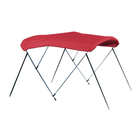
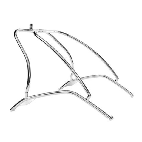
ADDA-TOP T-TOP User manual

1 | P a g e

2 | P a g e
You have purchased a quality aftermarket T-Top to upgrade your center
console boat! We thank you for choosing us! After you complete your
installation, remember to send us photos for our customer gallery and leave
your product reviews.
BEFORE YOU GET STARTED:
Read through this entire installation guide before beginning. Do an inventory check. Compare what you
received with the parts list below. If you are missing any parts, contact us before starting the
installation. Make all measurements before you begin to ensure the T-top is installed in the correct
position.
We proudly offer support for the lifetime of original ownership. If you need help or have installation
5pm EST.
NOTE: If you have a grab rail on your console, it may need to be removed prior to tower installation.
Removing the grab rail allows for the tower to fit snugly against your console.
NOTE: DO NOT ATTACH THE FEET OF THE TOWER TO YOUR DECK UNTIL THE VERY LAST STEP!
LIST OF RECOMMENDED TOOLS & SUPPLIES:
POWER DRILL
DRILL BITS
PHILIPS HEAD DRIVER BIT
WRENCHES (SOCKET OR
ADJUSTABLE)
ALLEN WRENCH SET
MEASURING TAPE
MARKER PEN
ANTI SEIZE LUBRICANT
3M 5200 MARINE ADHESIVE
A FRIEND TO HELP
PARTS LIST:
STARBOARD LEG
PORT LEG
FIBERGLASS TOP
(2) 3X5 STANDOFF BRACKETS
(2) 2X4 STANDOFF BRACKETS
(4) BACKING PLATES
(8) ROUND TOP WASHERS
(8) 5/16” STAINLESS BOLTS
(8) 5/16” STAINLESS NYLOC
NUTS
(24) STAINLESS WASHERS
(8) 3/8” STAINLESS PAN HEAD
SCREWS
(4) LOCKING T-NUT STAINLESS
STEEL BOLTS
(4) M10 STAINLESS NYLOC
NUTS
(8) STAINLESS #14 TAPPING
SCREWS

3 | P a g e
(1) STARBOARD AND (1) PORT LEG
FIBERGLASS TOP
(2) 3x5 STANDOFF BRACKETS
(2)2X4 STANDOFF BRACKETS
(4) BACKING PLATES
(8) ROUND TOP WASHERS

4 | P a g e
(8)-5/16” Stainless Bolts
(8) 3/8” Stainless Pan Head Screws
(8)-5/16” Stainless Nyloc Nuts
(4)-Stainless Locking T-bolts
(4)-M10 Stainless Nyloc Nuts
(8) Stainless #14 Tapping Screws
(24) Stainless Washers
S T E P O N E:
ATTACHING THE TOP TO THE TOWER
Your Top is predrilled with 8 holes for tower installation. We recommend using an elevated
surface to place your top where there is access to the pre-drilled holes. The box we ship our
system in can be used as a buffer between the gelcoat and the surface. You will notice there
are 3 injector ports on the top of your top. These are the resin infusion ports. They are on the
topside of the top, so they remain out of view.
Predrilled holes for tower installation (3) resin infusion ports appear on the top of the top

5 | P a g e
Take each designated leg and align with the pre-drilled holes in the top. Use the (8) 3/8”
Stainless Pan head screws and fasten. The (2) shorter pan head screws are for the rear pads.
The two large mounting pads on the tower go to the front and the small pads go to the rear.
(** we recommend applying anti-seize or 5200 for installing stainless hardware, Take a 3/8”
bolt and run anti-seize or 5200 marine silicone in and out of all pads before installing).
Tighten each bolt by hand to start and avoid cross-threading. Using an Allen wrench, tighten
each bolt the rest of the way.

6 | P a g e
S T E P T W O:
INSTALLATION OF THE OPTIONAL UPGRADES: ELECTRONICS BOX, GLOVE BOX, LED
LIGHTS & ROD RACKS
There are guide tabs on the underside of the top to align the e-box. The holes will need to be
drilled with a 1/4'” drill bit in the designated holes. Using the provided (6) 1/4 –20 pan head
bolts attach the e-box in the (6) designated spots where mounting holes are present. You can
also install any other optional upgrades at this time. The glove box and LED lights fit snugly
into the designated precut holes in your e-box.
S T E P T H R E E :
POSITIONING YOUR ASSEMBLED TOP & TOWER ON YOUR BOAT
Once both legs and electronics box are attached, use a friend to help hoist the top & tower
into your boat. (TOTAL WEIGHT IS 150 POUNDS, ASSEMBLED). Be sure to align the upright legs so
you are not blocking your access door.

7 | P a g e
At this stage, it is very important to know where you will be installing the stand-offs that
connect both the t-top’s leg sections to the center console unit.
(SEE ATTACHED DIAGRAM 6B) Your ADDA-TOP Tower is made with a universal groove that
allows for adjustability. Taking your locking T-bolt, align your standoffs where you can flush
mount one side to the console and the other to the rail. The side that attaches to the console
needs to be drilled for the (8) 5/16” stainless bolts. The stand-off allows for 2”-5” distances. 3M
5200 marine grade silicone is recommended for holding standoffs to the console. 2 standoffs
per side is required.
FOR MAXIMUM SUPPORT, IT IS
RECCOMMENDED THAT STAND-OFFS
BE MOUNTED IN THIS AREA.
IT IS IMPORTANT TO SELECT AN AREA
OF THE CONSOLE THAT IS FLAT AND
PERPENDICULAR TO THE
STANDOFFS.
THE DISTANCE BETWEEN A LEG AND
THE CONSOLE SHOULD BE BETWEEN
2 TO 5 INCHES.

8 | P a g e
Attaching the stand-offs help determine your port and starboard distances. Once all four
standoffs are in place, you will be ready to attach the feet to the deck.
S T E P F O U R:
ATTACHING YOUR FRAME TO YOUR DECK
Once you have your stand-off brackets attached you are clear to attach your feet. Drill a pilot
hole for the screws, using a 3/16” drill bit. Apply a generous amount of 5200 sealant in the
holes or any other marine grade silicone and run screws down until tight. Sealant can also be
added to the bottom of the pads as most boats have a sloped deck. Using a wet cloth, remove
excess sealant around each foot.

9 | P a g e
S T E P F I V E:
WIRING INSTRUCTIONS
You can easily wire LED lights or other electronics through your electronics box. The legs of
our tower are hollow and are a perfect place to keep wires tucked out of sight and away from
the elements. Drill an exit hole into your electronics box and pull wires down the hollow
starboard leg of the tower. There is a ½” opening at the top and bottom of the starboard leg
for a wire chase.
INSTALLATION COMPLETE!
Add your boat to our customer gallery! After you have installed your RT
Marine AddaTop T-Top, take some photos and send them to us –
[email protected]. We thank you for choosing RT Marine!

10 | P a g e
IMPORTANT NOTICES:
NOT A PLATFORM!!! NO JUMPING, DIVING,
SITTING, STANDING ON TOP!
-WE SUGGEST USING ANTI-SEIZE ON ALL BOLTS. STAINLESS BOLTS CAN SEIZE WHEN UNDER HEAT
AND PRESSURE.
WE RECOMMEND HAND TIGHTENING ALL HARDWARE BEFORE USING IMPACT WRENCHES.
-WE SUGGEST USING MARINE GRADE SILICONE (EX. 3M 5200) ON ALL MOUNTING AREAS.
- CARE & MAINTENANCE INFO:
The best method for cleaning any powder coated finish is by regularly washing it using a solution of clean
water and mild detergent. The entire surface, including all nooks and corners –should be cleaned using a
soft cloth or sponge, using nothing harsher than a natural bristle brush. This will remove any dirt,
minerals, and residue that could scratch or etch the finish. Rinse with clean water and dry with a
microfiber cloth. DO NOT USE abrasive pads, steel wool or other hard textured mediums because they
could permanently destroy the finish.
WE RECOMMEND CHECKING YOUR LOCKING T-NUTS FOR TIGHTNESS PERIODICALLY. USE A ½”
WRENCH AND HAND TIGHTEN AS NEEDED.

11 | P a g e
STAND OFF DIAGRAM (6B)
** You want to get your stand offs preferably in the lateral to the console and as close to the elbows as
possible. See diagram for reference. Optimal is as forward to the bow as possible on the lateral and as
high on the rear leg as possible. Each console is different and there are countless combinations, but you
are aiming to reduce vibration as high as possible and as close to the leg junctions.
Table of contents
Popular Boating Equipment manuals by other brands

Navnet
Navnet TZ Touch9 Connection guide

SPW
SPW VARIPROFILE VP-64 manual
Seastar Solutions
Seastar Solutions BayStar Plus installation instructions
Polyform
Polyform A Series quick start guide
West Marine
West Marine Regatta Timer Watch instruction manual

SLEIPNER MOTOR AS
SLEIPNER MOTOR AS PS600 Installation and user manual

Seastar Solutions
Seastar Solutions HO61 Series installation instructions
Attwood
Attwood 66448 Series installation instructions

Gumotex
Gumotex AIRGO manual

Uflex
Uflex UC 69-I Installation and maintenance manual
Garmin
Garmin GPSmap 8500 GRID installation instructions
Kobelt
Kobelt 2009 Owner's Operation, Installation & Maintenance Manual
