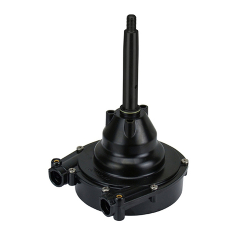
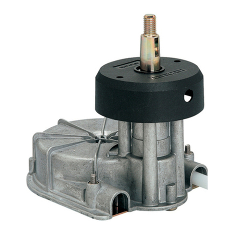
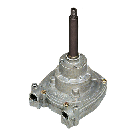
Ultraflex S39 User manual

SOCIO
R
Installationinstructions
CLAMPBLOCKFORSTEERINGCABLE
Istruzionidiinstallazione
SUPPORTO PER MONOCAVO
Instructionsdemontage
SUPPORT POURCABLEDEDIRECTION
UK
F
I
(Dr./Dis./Des. n°25185/a17/02/2015)
S39

ULTRAFLEX
pag.2 -
INSTALLATIONINSTRUCTIONS
ISTRUZIONI DI INSTALLAZIONE
INSTRUCTIONSDEMONTAGE
UK F
I
INTRODUCTION
WARNING
LETTERAINFORMATIVA LETTRED’INFORMATION
Il presentemanualediinstallazio-
neemanutenzionecostituisce par-
teintegrantedelprodottoedeve
esserefacilmentereperibiledal
personaleaddettoall'uso eallama-
nutenzionedellostesso.
L’utilizzatoreètenutoaconoscere
ilcontenutodelpresentemanuale.
ULTRAFLEX declinaogniresponsa-
bilitàpereventualiinesattezze
dovuteaderroridistampa, conte-
nutenelmanuale. Fermerestando
lecaratteristicheessenzialidelpro-
dottodescritto, ULTRAFLEX siriser-
va ildirittodiapportareeventuali
modifichedidescrizioni, dettaglie
illustrazioni, cheriterràopportuno
perilmiglioramentodellostesso,o
peresigenze dicaratterecostruttivo
ocommerciale, inqualunquemo-
mentoesenza impegnarsiadag-
giornaretempestivamentequesta
pubblicazione. TUTTIIDIRITTISONO
RISERVATI.Idirittidipubblicazio-
ne,imarchi,lesigleelefotografie
dei prodotti ULTRAFLEX presentiin
questomanualesonodiproprietà
ULTRAFLEX chenevietaqualsiasiri-
produzioneancheparziale.Ogni
curaèstatapostanellaraccoltae
nellaverificadelladocumentazio-
neperrenderequestomanualeil
piùcompletoecomprensibilepos-
sibile. Nulladiquantocontenuto
nellapresentepubblicazionepuò
essereinterpretatocomegaranzia
ocondizioneespressa oimplicita-
inclusa, noninvia limitativa,laga-
ranziadiidoneitàperun particola-
rescopo.Nulladiquantocontenuto
nellapresentepubblicazionepuò
inoltreessereinterpretatocome
modificaoasserzionedeitermini
diqualsivoglia contrattodiacquisto.
Alfinediassicurareilcorrettofun-
zionamentodelprodottoedeisuoi
componenti,lostessodeve essere
installatodapersonaleesperto. In
caso dirotturediparticomponenti
omalfunzionamento, rivolgersi al
personalespecializzatoocontatta-
reilnostroServizio Assistenza Tec-
nica.
AVVERTENZA AVERTISSEMENT
Cemanueld'installationetd'entretien
estunepartie intégranteduproduitet
ildoitêtrefacilementrepérablepar
lepersonnelpréposé àsonemploi et
àsonentretien.L’usagerdoit
connaîtrelecontenudecemanuel.
LaSociétéULTRAFLEX déclinetoute
responsabilitéencas d'inexactitudes
duesàdesfautes d'impression,
contenues danslemanuel.Bienque
les caractéristiques principales du
typedeproduitdécritnechangent
pas,laSociété ULTRAFLEX seréserve
ledroitdemodifierles descriptions,
les détailsetlesillustrationsqu'elle
jugeranécessairesafindel'améliorer,
soitpourdes exigencesdecaractère
constructifoucommercial,dans
n'importequelmomentetsansêtre
obligédemettreàjourlemanueltout
desuite. TOUSLESDROITSSONT
RESERVES.Lesdroitsdepublication,
lesmarques, lessigles etles photos
desproduits ULTRAFLEX contenus
dansce manuelappartiennentàla
Société ULTRAFLEX quieninterdit
toutesortedereproductionmême
partielle. Touslessoinsontétépris
pourrassembleretcontrôlerla
documentationcontenuedansce
manuelafindelerendreleplus
completetlepluscompréhensible
possible. Riendece quiestcontenu
danscettepublicationnepeutêtre
interprétécommegarantieou
conditionexpliciteouimplicite - y
compris,pasenvoielimitative,la
garantie d'aptitudepourunbut
particulier.Riendece quiestcontenu
danscettepublicationnepeutêtre
interprétécommemodificationou
assertiondestermesden'importe
quelcontratd'achat.
This installationandmaintenance
manualrepresentsanimportantpart
oftheproductandmustbeavailable
tothepeopleinchargeofitsuse and
maintenance.
Theusermustknowthecontentof
this manual.
ULTRAFLEX declinesallresponsibility
forpossiblemistakesinthismanual
duetoprintingerrors.
Apartfromtheessentialfeatures of
thedescribedproduct, ULTRAFLEX
reservestherighttomakethose
modifications,suchas descriptions,
detailsandillustrations, thatare
consideredtobesuitableforits
improvement,orfordesignorsales
requirements, atanymomentand
withoutbeingobligedtoupdatethis
publication.
ALLRIGHTSARE RESERVED.
Publishingrights, trademarks, part
numbersandphotographsof
ULTRAFLEX productscontainedinthis
manualare ULTRAFLEX property.
Greatcarehasbeentakenin
collectingandcheckingthe
documentationcontainedinthis
manualtomakeitas completeand
comprehensibleaspossible. Nothing
containedinthismanualcanbe
interpretedas warrantyeither
expressedorimplied-including,not
inarestrictedway, thesuitability
warrantyforanyspecialpurpose.
Nothingcontainedinthismanualcan
beinterpretedasamodificationor
confirmationofthetermsofany
purchasecontract.
Toensurethecorrectproductand
componentoperation,theproduct
mustbeinstalledbyqualifiedstaff.
Incaseofpartdamageor
malfunction,please contactthe
qualifiedstaff orourTechnical
Assistance Service.
Le produitdoitêtreinstallépardu
personnelforméafind'assurer
sonfonctionnementcorrectetcelui
deses composants. Encasde
rupturedeparties oudemauvais
fonctionnement,s'adresserau
personnelspécialisé oucontacter
notreServiced'Assistance
Technique.
ULTRAFLEX
-pag.3
INSTALLATIONINSTRUCTIONS
ISTRUZIONI DI INSTALLAZIONE
INSTRUCTIONSDEMONTAGE
UK F
I
WARRANTY GARANZIA GARANTIE
ULTRAFLEX garantiscecheisuoi
prodottisonocostruiti aregolad'arte
echesonoprivididifettidifabbri-
cazioneedimateriali.
Questagaranzia èvalidaperunpe-
riododidueannidecorrentidalla
datadifabbricazionedei prodottiad
eccezionedeicasiincuiquestisia-
noinstallatiedusatisubarcheda
lavoroocomunquesubarchead
utilizzo commerciale, nelqualcaso
lagaranziaèlimitataad1annodal-
ladatadifabbricazione.
Questagaranziaèlimitataallaso-
stituzioneoriparazionegratuitadel
pezzo che, entroilterminesuddet-
to, cisaràrestituitoinportofranco e
cherileveremoessereeffettivamen-
tedifettoso neimaterialio/enella
fabbricazione.
Èesclusodallagaranzia ogniequal-
siasialtrodannodirettooindiretto.In
particolare, èescluso dallagaranzia
edaogninostraresponsabilità(tran-
nequelladisostituireoriparare, nei
terminiecondizionisuddette,ipezzi
difettosi)ilmalfunzionamentodei no-
striprodottiqualorailloromancatoo
difettoso funzionamentosia
attribuibileadunaerratainstallazio-
neoaduso negligenteoimproprio.
Questagaranzianoncopreiprodotti
installatisubarchedacorsa outi-
lizzateincontesticompetitivi. Lede-
scrizionieleillustrazionidiquesto
manuales'intendonoforniteatitolo
indicativo.
Perinformazionidettagliatesipre-
gadicontattareilnostroServizio
Assistenza.
Icomponentidei sistemidiguida
ULTRAFLEX sonomarcati comeri-
chiestodalladirettiva 2013/53/UE.
Vi ricordiamochesulleimbarcazioni
marcateCEèobbligatorioinstalla-
resistemidiguidaicuicomponenti
sianomarcatiCE. Vi informiamoche
lagaranzia ULTRAFLEX decadeauto-
maticamentequaloraalcunicompo-
nenti ULTRAFLEX sianoinstallatiinun
sistemadiguidainsiemeaprodotti
dialtremarche.
ULTRAFLEX guarantees thatits
productsarewell designedandfree
frommanufacturingandmaterial
defects, foraperiodoftwoyears
fromthedateofmanufacturing.
Fortheproductswhichareinstalled
andusedonworkingorcommercial
boatsthewarrantyislimitedtoone
yearfromthedateofmanufacturing.
If duringthis periodtheproduct
provestobedefectivedueto
impropermaterialsand/or
manufacture,themanufacturerwill
repairorreplacethedefective parts
freeofcharge.
Directorindirectdamageis not
coveredbythiswarranty.Inparticular
thecompanyisnotresponsibleand
this warrantywill notcover the
damageresultingfromincorrect
installationoruse oftheproduct
(exceptforreplacementorrepairof
defective partsaccordingtothe
conditionsandtermsabove).
Thiswarrantydoesnotcoverthe
productsinstalledonrace boatsor
boatsusedincompetitions.
Thedescriptionsandillustrations
containedinthismanualshouldbe
usedasgeneralreference only.
Foranyfurtherinformationplease
contactourTechnicalAssistance
Service.
ULTRAFLEX steeringsystem
componentsaremarked
accordingtotheDirective2013/53/
EU.
WeremindyouthatonlyCE marked
steeringsystemsmustbeusedon
the boatsmarkedCE.Weinformyou
thatthe ULTRAFLEX warrantyis nullif
someULTRAFLEX componentsare
installedonasteeringsystem
togetherwithproductsofother
brands.
LaSociété ULTRAFLEX garantitqueses
produitssontfabriquésàrèglesd'art
etqu'ilsn'ontaucundéfautde
fabricationetdematériels.
Cettegarantie aunevaliditédedeux
annéesàpartirdeladatede
fabricationdesproduitsàl'exception
descasoùilssontinstallés etutilisés
surdes bateauxdetravailoude
commerce, car alorslagarantie est
limitéeàuneannée deladatede
fabrication.
Danslecasoù,pendantcettepériode
leproduits'avéreraitdéfectueuxà
causedesmatériauxutilisés ou/et
présentedes vicesdefabrication,le
fabricantleremplaceraoule
répareragratuitement.
Toutautredommagedirectouindirect
estexcludelagarantie.Enparticulier
laSociétéconstructrice n'estpas
responsableetcettegarantie ne
couvre pas lesdommages dérivant
d'uneinstallationincorrecteoud'un
emploiinadéquatouabusifdes
produits(àl'exceptiondu
remplacementoudelaréparationdes
piècesdéfectueuses danslestermes
etles délais susmentionnés).
Cettegarantie necouvre pas les
produitsinstallés surdes bateauxde
courseouutiliséspourdes
compétitions. Lesdescriptionsetles
illustrationscontenues dansce
manuelsontseulementàtitre
indicatif.
Pourtouteinformationdétaillée
contacternotreServiced'Assistance.
Lescomposantsdes systèmesde
conduite ULTRAFLEX sontpourvusde
lamarque enconformité
avec ladirective2013/53/UE.
Onrappellequesurlesbateaux
pourvusdelamarqueCEilest
obligatoired'installerdessystèmes
deconduite dontles composantssont
marquésCE. Nousvousinformons
quelagarantie ULTRAFLEX échoit
automatiquementaucasoùcertains
composants ULTRAFLEX seraient
installés dansun systèmede
gouvernementavecdes produitsde
marquesdifférentes.

ULTRAFLEX
pag.4-
INSTALLATIONINSTRUCTIONS
ISTRUZIONI DI INSTALLAZIONE
INSTRUCTIONSDEMONTAGE
UK F
I
TECHNICAL
ASSISTANCESERVICE
SERVICEASSISTANCE
TECHNIQUE
SERVIZIOASSISTENZA
TECNICA
UFLEX S.r.l.
ViaMiliteIgnoto,8A
16012 Busalla(GE)-Italy
Tel:+39.010.962.0239(Italy)
Tel:+39.010.962.0244(abroad-estero-étranger)
Fax: +39.010.962.0333
Email: ut@ultraflexgroup.it
www.ultraflexgroup.it
North-South-CentralAmerica:
UFLEX USA
6442ParklandDrive
Sarasota,FL34243
Tel:+1.941.351.2628
Fax: +1.941.360.9171
Email: uflex@uflexusa.com
www.uflexusa.com
NECESSARYTOOLS OUTILSNECESSAIRESUTENSILINECESSARI
Openendwrench13mm
Chiaveesagonale13mm
Clésix-pans 13 mm
Openendwrench10mm
Chiaveesagonale10mm
Clésix-pans 10 mm
Drill
Trapano
Perceuse
COMPONENTS COMPOSANTSCOMPONENTI
Openendwrench24mm
Chiaveesagonale24mm
Clésix-pans 24 mm
Pinza
Pliers
Pince
S39
A
B
F
C
I
H
L
K
G
J
D
E
TheS39clampblockisan
aluminiumandstainlesssteel
bracketequippedwithballjoint
forthesteeringcablepassage
nearthetransom.
LesupportS39estunétrieren
aluminium etenacierinox pourvu
d’articulationàrotulepourle
passageducâblede
gouvernementprèsdutableau
arrière.
Il supportoS39 èunastaffainal-
luminioeacciaioinoxdotatadi
snodosferico perilpassaggio del
cavo diguidainprossimitàdello
specchiodipoppa.
.
REF S39 S39 S39
A1tube 1tubo 1tuyau
B1ringnut 1 ghiera 1collier
C4screws
M6x40 4vitiM6x40 4visM6x40
D4elastic
washers
4rondelle
elastiche
4rondelles
élastiques
E4nutsM6 4dadi M6 4écrous M6
F1shaft 1alberino 1 arbre
G1nutM16 1dadoM16 1 écrouM16
H1bracket 1staffa 1étrier
I2clamp half
bearings
2semigusci
morsetto
2demi-
coquilles
étau
J3screws
M8x60 3vitiM8x60 3visM8x60
K3washers 3rondelle 3 rondelles
L3wing nuts 3dadi ad
alette 3papillons

ULTRAFLEX
-pag.5
INSTALLATIONINSTRUCTIONS
ISTRUZIONI DI INSTALLAZIONE
INSTRUCTIONSDEMONTAGE
UK F
I
INSTALLATION INSTALLAZIONE INSTALLATION
1Inserireilmonocavo neltubo
(A);avvitareildado(O)del
monocavoaltubofinoabattuta
(ilmonocavo deverisultaresoli-
dalealtubo),quindiposizionare
laghiera(B).
2Inserireiltubo(A)conmonocavo
neimorsetti(I)assiemeall’alberino
(F)dellastaffa(H).
Serrareiduesemigusci(I)del
morsettoutilizzandolequattroviti
(C),lerondelleelastiche(D)eidadi
(E).
AB
O
I
F
H
C
A
I
D
E
1Insérerlecâbledansletuyau
(A);visserl’écrou(O)ducâbleau
tuyaujusqu’à lesfaireentreren
contact(lecâbledoitêtre
solidairedutuyau),ensuite
positionnerlecollier(B).
2Insérerletuyau(A)avec le
câbledanslesétaux(I)avec
l’arbre(F)del’étrier(H).
Serrerlesdeuxdemi-coquilles (I)
del’étauàl’aidedesquatrevis
(C),desrondellesélastiques (D)et
des écrous(E).
1Insertthesteeringcableinto
thetube(A);screwthesteering
cable nut(O)tothetubeuntilit
touchesit(thesteeringcable
mustbeintegralwiththetube),
thenpositiontheringnut(B).
2Insertthetube(A)withthe
steeringcable intotheclamps(I)
withthe shaft (F)ofthe bracket(H).
Tightenthetwohalf bearings(I)
oftheclampbymeansofthefour
screws(C),theelastic washers(D)
andthenuts(E).

ULTRAFLEX
pag.6-
INSTALLATIONINSTRUCTIONS
ISTRUZIONI DI INSTALLAZIONE
INSTRUCTIONSDEMONTAGE
UK F
I
NOTA
La distanza“X”deltubo(A)dallospec-
chiodipoppaèregolabiledaun mi-
nimodi95mm(3.75”)adunmassi-
modi110mm(4.33”)(vedifigura).
G
A
5
X
TRANSOM/
SPECCHIODI
POPPA/
TABLEAU
ARRIERE TILLER ARM
BRACCIOMOTORE
BRASMOTEUR
H
XMAX=110
XMIN=95mm (3.75”)
3Conriferimentoallefigureripor-
tatesotto, perregolareladistanza
“X”deltubo (A)dallo specchio di pop-
pa,procederecomesegue:
-Inserireunpernonelforo(Y)
ø5mm(0.19”)dell’alberino(F)
perimpedirnelarotazione.
-Avvitareosvitarel’alberino(F)
finoadottenereladistanza “X”
voluta.
-Avvitareildado(G)finoabat-
tutasullastaffa(H) eserrare.
Sfilareilpernodalforo(Y)
ø5mm (0.19”) dell’alberino(F).
XMAX=110mm (4.33”)
Hole/Foro
/Trou=
ø5mm
NOTE
La distance “X”dutuyau(A)du
tableauarrièrepeutêtreréglée
d’un minimum de95mm (3.75”) à
unmaximum de110mm(4.33”)
(voirfigure).
3Ense réfèrantauxfigures ci-
dessous,pourréglerladistance “X”
dutuyau(A)dutableauarrière,
procédercommeilsuit:
-Insérerunpivotdansletrou
(Y) ø5mm (0.19”) del’arbre(F)
afind’enempêcherlarotation.
-Visseroudévisserl’arbre(F)
jusqu’àobtenirladistance“X”
désirée.
-Visserl’écrou(G)jusqu’àle
faireentrerencontactavec la
planche à bornes (H) etserrer.
Extrairelepivotdutrou(Y)
ø5mm (0.19”) del’arbre(F).
Thedistance “X”ofthetube(A)from
thetransomisadjustablefroma
minimumof95mm (3.75”)toa
maximumof110mm (4.33”) (see
picture).
NOTICE
3Referringtothepictures
below,toadjustthedistance “X”of
thetube(A)fromthetransom,
proceedasfollows:
-Insertapinintothehole(Y)
ø5mm (0.19”) ofthe shaft (F)in
ordertopreventitsrotation.
-Screworunscrewthe shaft (F)
uptoobtainingthedesired
distance “X”.
-Screwthenut(G)untilit
touches thebracket(H) and
tighten.Extractthepinfrom
thehole(Y) ø5mm (0.19”) ofthe
shaft (F).
Y
Fig.1
Fig.2

ULTRAFLEX
-pag.7
INSTALLATIONINSTRUCTIONS
ISTRUZIONI DI INSTALLAZIONE
INSTRUCTIONSDEMONTAGE
UK F
I
4Individuarelaposizionedella
staffa(H) sullospecchio dipoppa
(vedifigura)posizionandoil
monocavoametàcorsaefissare
l’estremitàdellostesso albrac-
cettomotore.
M
5Procedereconlaforaturadel-
lospecchiodipoppa(vedidima
diforaturaallegata)efissarela
staffatramiteleviti(L),lerondel-
le(M) eidadiadalette(N).
H
==
N
L
4Déterminerlapositionde
l’étrier(H)surletableauarrière
(voirfigure)enplaçantlecâble à
mi-courseetfixerl’extrémitéde
l’étrierlui-mêmeaubras moteur.
5Percerletableauarrière
(voirgabaritdeperçageannexé)
etfixerl’étrieràl’aidedes vis (L),
des rondelles (M) etdes papillons
(N).
5Drill thetransom(see drilling
templateattached)andfixthe
bracketby meansofthescrews
(L),thewashers(M) andthewing
nuts(N).
4Locatethepositionofthe
bracket(H)onthetransom(see
picture)by placingthesteering
cabletohalfstrokeandfixthe
steeringcableendtothetiller
arm.

DrillingtemplateforS39steeringcableclampblock
DimadiforaturasupportopermonocavoS39
GabaritdeperçagesupportpourcâblededirectionS39
UK
I
F
ULTRAFLEX
SOCIO
R
55mm (2.17”)
47,5mm (1.87”)
ø8,5mm (0.33”) n°3holes/fori /trous
Table of contents
Other Ultraflex Boating Equipment manuals

Ultraflex
Ultraflex UC 95 User manual

Ultraflex
Ultraflex UC 81 Manual

Ultraflex
Ultraflex B 310 Manual

Ultraflex
Ultraflex K18 User manual

Ultraflex
Ultraflex T73NRFC Manual

Ultraflex
Ultraflex A97 Manual

Ultraflex
Ultraflex OB/R5 User manual

Ultraflex
Ultraflex K65 User manual

Ultraflex
Ultraflex UC 130 Manual

Ultraflex
Ultraflex UFLEX ZTF Tiller System KIT QU1 User manual