NuTone RDFUWT User manual

RDFUWT
Premium
Radiation Damper
INSTALLATION GUIDE
READ AND SAVE THESE INSTRUCTIONS
Installer: leave this guide with homeowner.
Register your product online at: www.broan.com/register or www.nutone.com/register.
Easy installation
© 2016 Broan-NuTone LLC

RDFUWT – Installation Guide
Page 2
For use with 1, 2, or 3-Hour-Rated Floor-Ceiling and Roof-Ceiling Designs.
UL/ cUL Listed for use in the following Floor Ceiling and Roof Ceiling Assemblies: L521, L528, L546,
L558, L562, L574, L576, L581, L583, L585, P522, P533, P538, P545, and P547 when installed per
the following instructions:
Flat Ceiling / Horizontal Mount Only.
For use with the following ventilation fan models:
Broan XB50, XB50L, XB80, XB80L, XB110, XB110L, XB110H, XB110HL, ZB80, ZB80M, ZB110,
ZB110H, ZB110M, ZB80L, ZB80ML, ZB110L, ZB110HL, ZB110ML, QT130E, QT130LE, QT140E,
QT140LE, QTXE150, QTXE150FLT
Broan Canada XB50C, XB90C, XB90LC, XB90HC, XB110C, XB110LC, XB110HC, ZB110C, ZB90C, ZB110LC, ZB90LC,
ZB110HC, ZB110MC, ZB90MC, ZB90HC, ZB110MLC, ZB90MLC
NuTone QTN130E, QTN130LE1, QTXEN150, QTXEN150FLT, XN50, XN50L, XN80, XN80L, XN110, XN110L, XN110H,
XN110HL, ZN80, ZN80M, ZN110, ZN110H, ZN110M, ZN80L, ZN80ML, ZN110L, ZN110HL, ZN110ML
NuTone Canada XN50C, XN90C, XN110C, XN90LC, XN90HC, XN110LC, XN110HC, ZN90C, ZN90LC, ZN90HC, ZN90MC,
ZN90MLC, ZN110C, ZN110LC, ZN110HC, ZN110MC, ZN110MLC
Usage
SEE DETAILS ON
UL CLASSIFICATION
MARKING ON PRODUCT
Prepare Fan
The following steps are best performed on a work surface
before fan installation. Protect counter tops by placing
corrugated sheet under the fan.
1
2
3
1. Remove blower and all packing material from fan
housing.
2. Assemble SUPPORT BRACKET (A) (supplied with
radiation damper) to fan blower as shown. Secure the
bracket to motor studs with (2) #8-32 HEX NUTS (B)
supplied in radiation damper parts bag.
A
B

RDFUWT – Installation Guide
Page 3
D
E
H
F
G
3. Reinstall blower into fan housing. Install (2) #8 x ½” HEX HEAD SHEET METAL
SCREWS (C) supplied in fan parts bag.
4. Slide (4) MOUNTING BRACKETS (D) into slots on four sides of RADIATION
DAMPER EXTENSION FRAME (E). Make sure they snap into place and are
securely engaged after assembly.
5. Center the radiation damper over the fan housing. Make sure NOTCH (F) is
correctly positioned relative to the DUCT CONNECTOR OPENING (G).
6. Align radiation damper brackets with holes in the fan housing. Secure brackets to
fan housing with (4) #8 X 3/8” SHEET METAL SCREWS (H) (Supplied in radiation
damper parts bag.)
C
C
Steps 7 through 11:
Lighted Fans, Humidity-Sensing Fans, or
Motion Sensing Fans ONLY.
For fans not equipped with a light, a humidity sensor or a
motion sensor: Skip to Step 12.
7. Make lead wires longer. Purchase jumper kit model
RDJUMPU from your local Broan-NuTone dealer or
distributor.
Each kit contains:
1 - Jumper for lighted fan models
1 - Jumper for sensor fan models
8a. For fans equipped with lights, connect one end of the
LIGHTING JUMPER (I) to mating connector in the
fan’s wiring box.
J
I
8b. For fans equipped with humidity or motion sensors,
connect one end of the SENSOR JUMPER (J) to
mating connector in the fan’s wiring box.
9. Route JUMPER(S) (I) (J) towards the NOTCH (F) in
the damper frame.
10. Press jumper wires into PLASTIC SPLIT TUBE
INSULATOR (L) (supplied in damper parts bag). Push
plastic split tubing into NOTCH (F) opening.
11. Align tab on CABLE CLAMP (M) with mating slot in
damper extension. Secure clamp with supplied #8 x
3/8” SHEET METAL SCREW (H).
H
M
L

RDFUWT – Installation Guide
Page 4
L
snap!
snap!
O
P
Step 12:
XB, ZB, XN, ZN Models ONLY
12. Slide MOUNTING FRAME (O) onto fan housing. Pull
frame up around housing until it snaps into place.
Secure mounting frame to fan housing with (2) #8
X 3/8” FLAT HEAD SHEET METAL SCREWS (P)
supplied in the fan parts bag.
Step 13:
QT Models ONLY
13. Attach MOUNTING CHANNELS (Q) to housing using
SCREWS (R) supplied in fan parts bag.
Insert SLIDE BRACKETS (S) into mounting channels.
Q
R
S
SCREW FROM
PARTS BAG
INSERT
TAB INTO
SLOT IN
HOUSING
TOP AND BOTTOM FLANGES
REMAIN OUTSIDE OF HOUSING
14. Install 6” DUCT CONNECTOR (T) to fan housing and
secure with screw supplied in fan parts bag.
T

RDFUWT – Installation Guide
Page 5
12”
ON-CENTER
U
Prepare Ceiling & Install Fan in Ceiling
This radiation Damper and Fan Combination is UL/ cUL
Listed for use in the following Floor Ceiling and Roof
Ceiling Assemblies: L521, L528, L546, L558, L562, L574,
L576, L581, L583, L585, P522, P533, P538, P545, and
P547.
15. Install additional 2 X 4 VERTICAL BLOCKS (U) as
shown.
16. Make sure lower edge of radiation damper is flush
with INTERIOR SIDE OF FINISHED CEILING.
17. Securely fasten mounting support brackets to (4)
vertical blocks
18. Attach round metal duct to the duct connector
and discharge air to an outside location. Seal all
connection joints with duct tape.
Connect Wiring
19. Refer to instructions supplied with the fan for various
electrical wiring configurations.
20. Install MASK (V) supplied with the fan to protect damper
and fan from drywall spray, construction dust, etc.
21. Finish ceiling around radiation damper opening. Ceiling
opening must be no larger than the outside of the
radiation damper.
Finish Installation
22. Remove MASK (V) from housing.
23. Fasten (2) PLASTER SUPPORTS (W) to the
radiation damper extension with (6) #8 X 3/8” SHEET
METAL SCREWS (X). (Supplied in radiation damper
parts bag.)
V
W
X

RDFUWT – Installation Guide
Page 6
99045700C
Service Feature For Fans
Limited Warranty
Warranty Period and Exclusions:Broan-NuTone LLC (the “Company”) warrants to the original consumer purchaser of its product (“you”) that the product (the “Product”) will be free from material defects in the Product or its
workmanship for a period of one (1) year from the date of original purchase.
The limited warranty period for any replacement parts provided by the Company and for any Products repaired or replaced under this limited warranty shall be the remainder of the original warranty period.
This warranty does not cover speed controls, fluorescent lamp starters, tubes, halogen and incandescent bulbs, fuses, filters, ducts, roof caps, wall caps and other accessories for ducting that may be purchased separately and
installed with the Product. This warranty also does not cover (a)normal maintenance and service, (b)normal wear and tear, (c)any Products or parts which have been subject to misuse, abuse, abnormal usage, negligence, accident,
improper or insufficient maintenance, storage or repair (other than repair by the Company), (d)damage caused by faulty installation, or installation or use contrary to recommendations or instructions, (e)any Product that has been
moved from its original point of installation, (f)damage caused by environmental or natural elements, (g)damage in transit, (h)natural wear of finish, (i)Products in commercial or nonresidential use, or (j)damage caused by fire,
flood or other act of God. This warranty covers only Products sold to original consumers in the United States by the Company or U.S. distributors authorized by the Company.
This warranty supersedes all prior warranties and is not transferable from the original consumer purchaser.
No Other Warranties: This Limited Warranty contains the Company’s sole obligation and your sole remedy for defective products. The foregoing warranties are exclusive and in lieu of any other warranties, express or implied. THE
COMPANY DISCLAIMS AND EXCLUDES ALL OTHER EXPRESS WARRANTIES, AND DISCLAIMS AND EXCLUDES ALL WARRANTIES IMPLIED BY LAW, INCLUDING WITHOUT LIMITATION THOSE OF MERCHANTABILITY AND
FITNESS FOR A PARTICULAR PURPOSE. To the extent that applicable law prohibits the exclusion of implied warranties, the duration of any applicable implied warranty is limited to the period specified for the express warranty
above. Some states do not allow limitations on how long an implied warranty lasts, so the above limitation may not apply to you. Any oral or written description of the Product is for the sole purpose of identifying it and shall not be
construed as an express warranty.
Whenever possible, each provision of this Limited Warranty shall be interpreted in such manner as to be effective and valid under applicable law, but if any provision is held to be prohibited or invalid, such provision shall be ineffective
only to the extent of such prohibition or invalidity, without invalidating the remainder of such provision or the other remaining provisions of the Limited Warranty.
Remedy: During the applicable limited warranty period, the Company will, at its option, provide replacement parts for, or repair or replace, without charge, any Product or part thereof, to the extent the Company finds it to be covered
by and in breach of this limited warranty under normal use and service. The Company will ship the repaired or replaced Product or replacement parts to you at no charge. You are responsible for all costs for removal, reinstallation and
shipping, insurance or other freight charges incurred in the shipment of the Product or part to the Company. If you must send the Product or part to the Company, as instructed by the Company, you must properly pack the Product
or part—the Company is not responsible for damage in transit. The Company reserves the right to utilize reconditioned, refurbished, repaired or remanufactured Products or parts in the warranty repair or replacement process. Such
Products and parts will be comparable in function and performance to an original Product or part and warranted for the remainder of the original warranty period.
Exclusion of Damages: THE COMPANY’S OBLIGATION TO PROVIDE REPLACEMENT PARTS, OR REPAIR OR REPLACE, AT THE COMPANY’S OPTION, SHALL BE YOUR SOLE AND EXCLUSIVE REMEDY UNDER THIS LIMITED
WARRANTY AND THE COMPANY’S SOLE AND EXCLUSIVE OBLIGATION. THE COMPANY SHALL NOT BE LIABLE FOR INCIDENTAL, INDIRECT, CONSEQUENTIAL OR SPECIAL DAMAGES ARISING OUT OF OR IN CONNECTION
WITH THE PRODUCT, ITS USE OR PERFORMANCE.
Some states do not allow the exclusion or limitation of incidental or consequential damages, so the above limitation or exclusion may not apply to you. This warranty gives you specific legal rights, and you may also have other rights,
which vary from state to state.
This warranty covers only replacement or repair of defective Products or parts thereof at the Company’s main facility and does not include the cost of field service travel and living expenses.
Any assistance the Company provides to or procures for you outside the terms, limitations or exclusions of this limited warranty will not constitute a waiver of such terms, limitations or exclusions, nor will such assistance extend
or revive the warranty.
The Company will not reimburse you for any expenses incurred by you in repairing or replacing any defective Product, except for those incurred with the Company’s prior written permission.
How to Obtain Warranty Service: To qualify for warranty service, you must (a)notify the Company at the address or telephone number stated below within seven (7)days of discovering the covered defect, (b)give the model number
and part identification and (c)describe the nature of any defect in the Product or part. At the time of requesting warranty service, you must present evidence of the original purchase date. If you cannot provide a copy of the original
written limited warranty, then the terms of the Company’s most current written limited warranty for your particular product will control.The most current limited written warranties for the Company’s products can be found at www.
broan.com .
Broan-NuTone LLC 926 West State Street Hartford, WI 53027 www.broan.com 800-637-1453
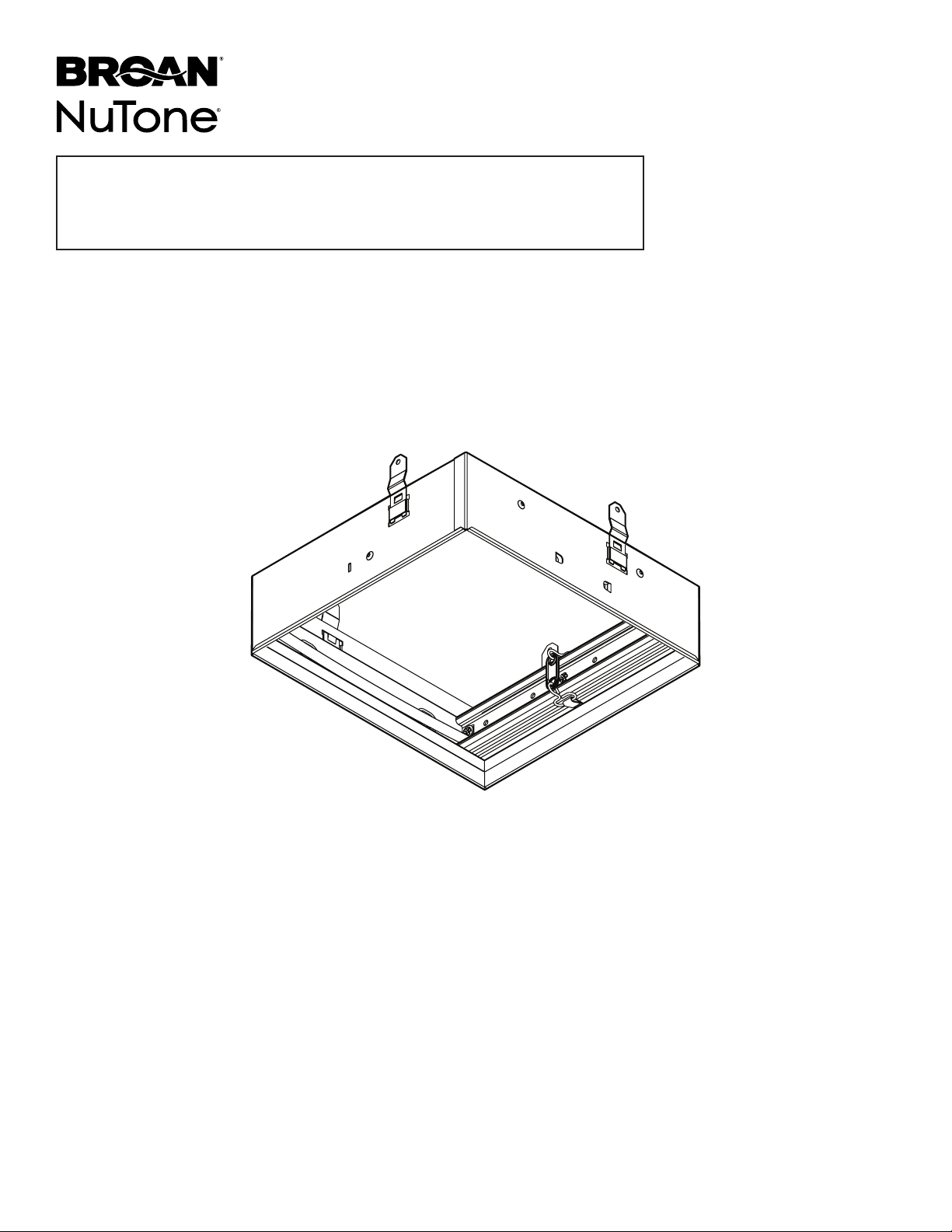
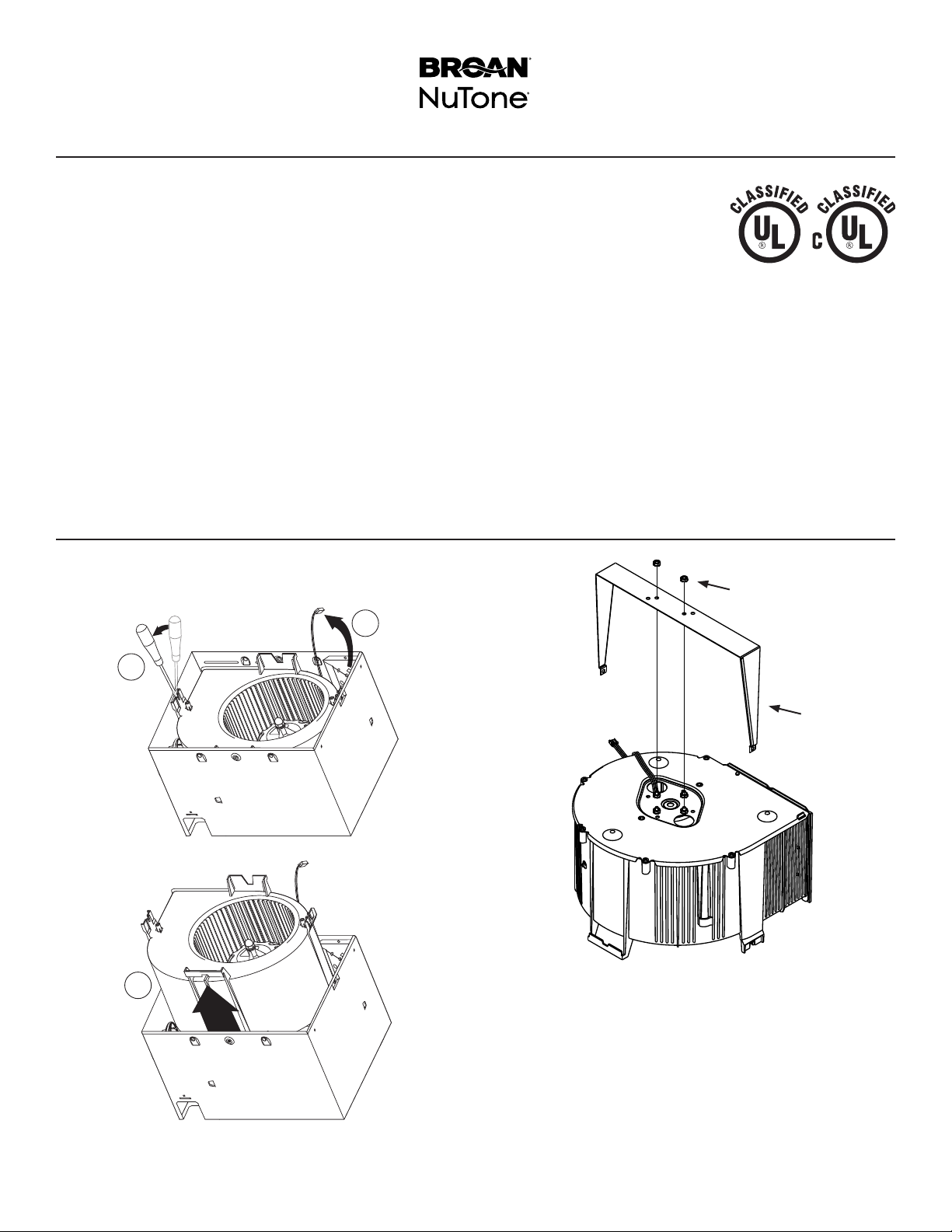
If your ventilation fan needs service, the inner damper can
be removed from the outer frame without disturbing the
surrounding ceiling material.
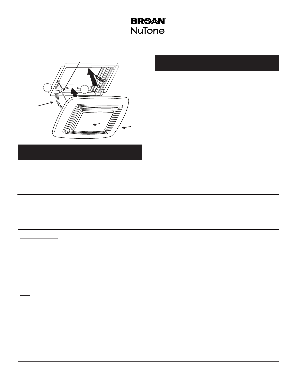
Install Grille
12
Step 24:
Lighted Fans ONLY.
24. Attach connector from the LIGHT JUMPER WIRE (I)
to mating connector(s) from the grille.
YZ
I
J
Remove the grille and disconnect all electrical connections
from the grille.
Remove (4) screws, then lower the inner damper to access
ventilation fan. Replace the inner damper before operating fan.
Step 25:
Humidity-Sensing Fans and Motion Sensing Fans ONLY.
25. Connect SENSOR JUMPER WIRE (J) into the sen-
sors connector located on the grille.
24. Squeeze 2 GRILLE SPRINGS (Y) and slide into tabs
on the radiation damper frame. Push GRILLE (Z) until
it’s tight against ceiling surface.
If additional clearance is required between ceiling and
grille, replace grille springs with longer ones (provided
in parts bag).

GUÍA DE
INSTALACIÓN
del Regulador de
Radiación de Primera
Calidad
RDFUWT
LEA Y CONSERVE ESTAS INSTRUCCIONES
Instalador: Deje esta guía con el dueño de la casa.
Registre su producto en el sitio web: www.broan.com/register o www.nutone.com/register.
Instalación sencilla
© 2016 Broan-NuTone LLC

Guía de instalación del RDFUWT
Página 8
Para usarse en los diseños de piso a cielo raso y techo a cielo raso con clasificación de 1, 2 o 3 horas.
Tiene certificación de UL/ cUL para usarse en los siguientes conjuntos de cielo raso a piso y cielo
raso a techo: L521, L528, L546, L558, L562, L574, L576, L581, L583, L585, P522, P533, P538,
P545, y P547 al instalarlo según las siguientes instrucciones:
Solamente montaje horizontal / en cielo raso plano.
Para usarse con los siguientes modelos de ventilador:
Broan XB50, XB50L, XB80, XB80L, XB110, XB110L, XB110H, XB110HL, ZB80, ZB80M, ZB110,
ZB110H, ZB110M, ZB80L, ZB80ML, ZB110L, ZB110HL, ZB110ML, QT130E, QT130LE, QT140E,
QT140LE, QTXE150, QTXE150FLT
Broan Canada XB50C, XB90C, XB90LC, XB90HC, XB110C, XB110LC, XB110HC, ZB110C, ZB90C, ZB110LC, ZB90LC,
ZB110HC, ZB110MC, ZB90MC, ZB90HC, ZB110MLC, ZB90MLC
NuTone QTN130E, QTN130LE1, QTXEN150, QTXEN150FLT, XN50, XN50L, XN80, XN80L, XN110, XN110L, XN110H,
XN110HL, ZN80, ZN80M, ZN110, ZN110H, ZN110M, ZN80L, ZN80ML, ZN110L, ZN110HL, ZN110ML
NuTone Canada XN50C, XN90C, XN110C, XN90LC, XN90HC, XN110LC, XN110HC, ZN90C, ZN90LC, ZN90HC, ZN90MC,
ZN90MLC, ZN110C, ZN110LC, ZN110HC, ZN110MC, ZN110MLC
Uso
VEA LOS DETALLES
EN LA MARCA DE
CLASIFICACIÓN UL
DELPRODUCTO
Preparación del ventilador
Los siguientes pasos se realizan mejor sobre una superficie
de trabajo antes de instalar el ventilador. Proteja el mostrador
colocando una hoja corrugada debajo del ventilador.
1
2
3
1. Retire el soplador y todo el material de embalaje de la cubierta
del ventilador.
2. Monte el SOPORTE DE APOYO (A) (suministrado con el
regulador de radiación) en el soplador del ventilador, como
se muestra. Asegure el soporte a los montantes del motor
con dos (2) TUERCAS HEXAGONALES #8-32 (B) que se
suministran en la bolsa de piezas del regulador de radiación.
A
B

Guía de instalación del RDFUWT
Página 9
D
E
H
F
G
3. Reinstale el soplador en la cubierta del ventilador. Instale dos (2) TORNILLOS DE CHAPA
METÁLICA DE CABEZA HEX #8 X 1/2 PULG. (C) que se suministran en la bolsa de
piezas del regulador.
4. Deslice cuatro (4) SOPORTES DE MONTAJE (D) en las ranuras en cuatro lados del
MARCO DE EXTENSIÓN DEL REGULADOR DE RADIACIÓN (E). Después del montaje,
asegúrese de que encajen a presión en su lugar y se enganchen de formasegura.
5. Centre el regulador de radiación sobre la cubierta del ventilador. Asegúrese de que
la MUESCA (F) esté colocada correctamente en relación con la ABERTURA DEL
CONECTOR DE CONDUCTO (G).
6. Alinee los soportes del regulador de radiación con los orificios en la cubierta del ventilador.
Asegure los soportes a la cubierta del ventilador con cuatro (4) TORNILLOS DE CHAPA
METÁLICA #8 X 3/8 PULG. (H) (Se suministran en la bolsa de piezas del regulador de
radiación)
C
C
Pasos 7 a 11: SOLAMENTE ventiladores con luz,
ventiladores con sensor de humedad y ventiladores con
sensor de movimiento.
Para ventiladores que no estén equipados con luz, sensor de
humedad o sensor de movimiento: Diríjase al paso 12.
7. Alargue los cables principales. Adquiera el juego de puentes
modelo RDJUMPU en su distribuidor o concesionario
autorizado de Broan-NuTone.
Cada juego contiene:
1 - puente para los modelos de ventilador con luz
1 - puente para los modelos de ventilador con sensor
8a. Para ventiladores equipados con luces, conecte un
extremo del PUENTE DE ILUMINACIÓN (I) al conector
correspondiente en la caja de cableado del ventilador.
J
I
8b. Para ventiladores equipados con sensores de humedad
o de movimiento, conecte un extremo del PUENTE DEL
SENSOR (J) al conector correspondiente en la caja de
cableado del ventilador.
9. Tienda los PUENTES (I) (J) hacia la MUESCA (F) en el
marco del regulador.
10. Presione los cables puente en el AISLANTE DE TUBO
DIVIDIDO DE PLÁSTICO (L) (suministrado en la bolsa de
piezas del regulador). Empuje el tubo dividido de plástico
dentro de la abertura de la MUESCA (F).
11. Alinee la lengüeta de la ABRAZADERA DEL CABLE (M)
con la ranura correspondiente en la extensión del regulador.
Fije la abrazadera con el TORNILLO DE CHAPA METÁLICA
#8 X 3/8 PULG. (H) suministrado.
H
M
L

Guía de instalación del RDFUWT
Página 10
L
snap!
chasquido
O
P
Paso 12:
SOLAMENTE modelos XB, ZB, XN, ZN
12. Deslice el MARCO DE MONTAJE (O) en la cubierta del
ventilador. Suba el marco alrededor de la cubierta hasta que
quede sujetado a presión.
Fije el marco de montaje a la cubierta del ventilador con
dos (2) TORNILLOS DE CHAPA METÁLICA DE CABEZA
PLANA #8 X 3/8 PULG. (P) que se suministran en la bolsa
de piezas del ventilador.
Paso 13:
SOLAMENTE modelos QT
13. Sujete los CANALES DE MONTAJE (Q) a la cubierta con
los TORNILLOS (R) que se suministran en la bolsa de
piezas del ventilador.
Introduzca los SOPORTES DESLIZANTES (S) en los
canales de montaje.
Q
R
S
TORNILLO
DE LA BOLSA
DE PIEZAS
INTRODUZCA
LA PESTAÑA EN
LA RANURA EN
LA CUBIERTA
LAS BRIDAS SUPERIOR E
INFERIOR PERMANECEN
FUERA DE LA CUBIERTA
14. Instale el CONECTOR DE CONDUCTO DE 6 PULG. (15 CM)
(T) en la cubierta del ventilador y asegúrelo con el tornillo
incluido en la bolsa de piezas del ventilador.
T

Guía de instalación del RDFUWT
Página 11
12 pulg.
(30.5 cm)
DE CENTRO A CENTRO
U
Prepare el cielo raso e instale allí el ventilador
La combinación de regulador de radiación y ventilador tiene
certificación de UL/cUL para usarse en los siguientes conjuntos
de cielo raso a piso y cielo raso a techo: L521, L528, L546, L558,
L562, L574, L576, L581, L583, L585, P522, P533, P538, P545
yP547.
15. Instale BLOQUES VERTICALES 2X4 ADICIONALES (U),
como se muestra.
16. Asegúrese de que el borde inferior del regulador de
radiación esté al ras con el LADO INTERIOR DEL CIELO
RASO TERMINADO.
17. Fije con firmeza los soportes de montaje de apoyo en los
cuatro (4) bloques verticales
18. Fije el conducto metálico redondo al conector para
conductos y haga que se descargue el aire en un lugar
en el exterior. Selle todas las juntas de conexión con cinta
paraconductos.
Conecte el cableado
19. Consulte las instrucciones suministradas con el ventilador
para ver las diferentes configuraciones de cableado
eléctrico.
20. Instale la COBERTURA (V) suministrada con el ventilador a fin
de proteger el regulador y el ventilador contra los rociados de
yeso, polvos de construcción, etc.
21. Termine el cielo raso alrededor de la abertura del regulador. La
abertura del cielo raso no debe ser más grande que el exterior
del regulador de radiación.
Termine la instalación
22. Retire la COBERTURA (V) de la cubierta.
23. Fije dos (2) SOPORTES DEYESO (W) a la extensión del
regulador de radiación con seis (6) TORNILLOS DE CHAPA
METÁLICA #8 X 3/8 PULG. (X). (Se suministran en la bolsa de
piezas del regulador deradiación).
V
W
X

Guía de instalación del RDFUWT
Página 12
99045700C
Función de servicio para ventiladores
Garantía limitada
Periodo y exclusiones de la garantía:Broan-NuTone LLC (la “Compañía”) garantiza al consumidor comprador original de su producto (“usted”) que el producto (el “Producto”) estará libre de defectos en materiales o en mano
de obra, por un periodo de un (1) año a partir de la fecha de compra original.
El periodo de garantía limitada para cualquier pieza de repuesto proporcionada por la compañía y para cualquier Producto reparado o reemplazado bajo esta garantía limitada debe ser lo que reste del periodo de garantía original.
Esta garantía no cubre controles de velocidad, arrancadores de lámparas fluorescentes, tubos, bombillas de halógeno e incandescentes, fusibles, filtros, conductos, tapas de techo, tapas de pared ni otros accesorios que
pudieran ser comprados por separado e instalados con el producto. Esta garantía tampoco cubre (a) mantenimiento y servicio normal, (b) uso y desgaste normal, (c) Productos o piezas sujetos a mal uso, abuso, uso anormal,
negligencia, accidente, mantenimiento inadecuado o insuficiente, almacenamiento o reparación (que no sea reparación por parte de la Compañía), (d) daños causados por instalación defectuosa, o bien instalación o uso
contrario a las recomendaciones o instrucciones, (e) cualquier Producto que se haya movido de su punto de instalación original, (f) daños ocasionados por el medio ambiente o los elementos naturales, (g) daños en tránsito,
(h) desgaste natural del acabado, (i) Productos en uso comercial o no residencial, o (j) daños ocasionados por incendio, inundación u otro caso fortuito. Esta garantía cubre solamente Productos vendidos a clientes originales
en los Estados Unidos por la Compañía o a distribuidores de EE. UU. autorizados por la Compañía.
Esta garantía sustituye todas las garantías anteriores y no es transferible del comprador consumidor original.
No hay otras garantías: Esta garantía limitada contiene la única obligación de la Compañía y su único recurso ante productos defectuosos. Las garantías anteriores son exclusivas y en lugar de cualquier otra garantía, expresa
o implícita. LA COMPAÑÍA NIEGA Y EXCLUYE CUALQUIER OTRA GARANTÍA EXPRESA, Y NIEGA Y EXCLUYE TODAS LAS GARANTÍAS IMPLÍCITAS POR LEY, INCLUYENDO, ENTRE OTRAS, LAS DE COMERCIALIZACIÓN Y
APTITUD PARA UN PROPÓSITO EN PARTICULAR. Hasta el grado en que la ley aplicable prohíba la exclusión de las garantías implícitas, la duración de cualquier garantía implícita aplicable está limitada al periodo especificado
para la garantía expresa antes mencionada. Algunos estados no permiten limitaciones en la duración de una garantía implícita, así que la limitación anterior tal vez no aplique en su caso. Cualquier descripción verbal o escrita
del Producto es para el único propósito de identificarlo y no deberá considerarse como una garantía expresa.
Siempre que sea posible, toda disposición de esta garantía limitada deberá ser interpretada de tal forma que sea efectiva y válida de conformidad con la ley aplicable, pero si alguna disposición fuera considerada prohibida o
inválida, quedará sin efecto solo en virtud de dicha prohibición o invalidez, sin invalidar el resto de dicha disposición o las demás disposiciones restantes de la garantía limitada.
Recurso: Durante el periodo de garantía limitada aplicable, la Compañía, a su opción, suministrará piezas de repuesto, o reparará o reemplazará, sin cargo alguno, cualquier Producto o pieza del mismo, hasta el grado en que
la Compañía lo encuentre cubierto bajo esta garantía limitada y en incumplimiento de la misma en condiciones normales de uso y servicio. La Compañía le enviará el Producto reparado o reemplazado o las piezas de repuesto
sin cargo. Usted es responsable de todos los costos de retiro, reinstalación y envío, seguro u otros cargos de flete incurridos en el envío del Producto o pieza a la Compañía. Si debe enviar el Producto o la pieza a la Compañía,
tal como lo indique la Compañía, debe empaquetar adecuadamente el Producto o la pieza: la Compañía no se hace responsable por los daños en tránsito. La Compañía se reserva el derecho de utilizar Productos o piezas
reacondicionados, renovados, reparados o refabricados en el proceso de reemplazo o reparación de garantía. Dichos Productos y piezas serán comparables en función y desempeño a un Producto o una pieza original y tendrán
garantía durante el resto del periodo de la garantía original.
Exclusión de daños: LA OBLIGACIÓN DE LA COMPAÑÍA DE SUMINISTRAR PIEZAS DE REPUESTO, O DE REPARAR O REEMPLAZAR, A OPCIÓN DE LA COMPAÑÍA, SERÁ SU ÚNICO Y EXCLUSIVO RECURSO BAJO ESTA
GARANTÍA LIMITADA, Y LA ÚNICA Y EXCLUSIVA OBLIGACIÓN DE LA COMPAÑÍA. LA COMPAÑÍA NO SERÁ RESPONSABLE POR DAÑOS INCIDENTALES, INDIRECTOS, RESULTANTES O ESPECIALES QUE SURJAN POR EL
USO O DESEMPEÑO DEL PRODUCTO, O EN RELACIÓN CON EL MISMO.
Algunos estados no permiten la exclusión o limitación de daños incidentales o resultantes, por lo que la limitación antes mencionada podría no aplicarse a usted. Esta garantía le otorga derechos legales específicos, y usted
podría tener otros derechos que varían de un estado a otro.
Esta garantía cubre únicamente el reemplazo o la reparación de Productos defectuosos o piezas de los mismos en la planta principal de la Compañía, y no incluye el costo del viaje para el servicio de campo ni los viáticos.
Cualquier asistencia que proporcione o procure la Compañía para usted fuera de los términos, limitaciones o exclusiones de esta garantía limitada no constituirá una renuncia a dichos términos, limitaciones o exclusiones, ni
dicha asistencia extenderá o renovará la garantía.
La Compañía no le reembolsará ningún gasto en el que usted haya incurrido al reparar o reemplazar cualquier Producto defectuoso, excepto los incurridos con el permiso previo por escrito de la Compañía.
Cómo obtener el servicio cubierto por la garantía: Para tener derecho al servicio cubierto por la garantía, usted debe (a) notificar a la Compañía a la dirección o número de teléfono que aparecen abajo en un plazo de siete (7)
días después de descubrir el defecto cubierto, (b) proporcionar el número de modelo y la identificación de la pieza y (c) describir la naturaleza de cualquier defecto en el Producto o la pieza. En el momento de solicitar el servicio
cubierto por la garantía, debe presentar un comprobante de la fecha de compra original. Si usted no puede presentar una copia de la garantía limitada original por escrito, entonces regirán los términos de la garantía limitada
por escrito más actualizada de la compañía para su producto en particular. Las garantías limitadas por escrito más actualizadas para los productos de la Compañía se pueden encontrar en www.broan.com.
Broan-NuTone LLC 926 West State Street, Hartford, WI 53027 www.broan.com 800-637-1453
Si su ventilador necesita servicios de reparación/mantenimiento,
es posible quitar el regulador interior del marco exterior sin
perturbar el material del cielo raso circundante.
Instale la rejilla
12
Paso 24:
SOLAMENTE ventiladores con luz
24. Fije el conector del CABLE PUENTE DE LA LUZ (I) a los
conectores correspondientes de la rejilla.
YZ
I
J
Quite la rejilla y desconecte todas sus conexiones eléctricas.
Quite los cuatro (4) tornillos y luego baje el regulador interior
para tener acceso al ventilador. Reinstale el regulador interior
antes de activar el ventilador.
Paso 25:
SOLAMENTE ventiladores con sensor de humedad y
ventiladores con sensor de movimiento
25. Conecte el CABLE PUENTE DEL SENSOR (J) en el conector
de sensores ubicado en la rejilla.
26. Comprima 2 RESORTES DE LA REJILLA (Y) y deslícelos
dentro de las lengüetas del marco del regulador de radiación.
Empuje la REJILLA (Z) hasta que esté firme contra la
superficie del cielo raso.
Si es necesaria una mayor separación entre el cielo raso y la
rejilla, reemplace los resortes de la rejilla por unos más largos
(suministrados en la bolsa de piezas).
Other manuals for RDFUWT
1
Table of contents
Languages:
Other NuTone Fire And Smoke Damper manuals
Popular Fire And Smoke Damper manuals by other brands

Trox Technik
Trox Technik EK2-EU-FF installation manual

Trox Technik
Trox Technik FKR-EU Installation and operating manual

klimaoprema
klimaoprema FDC25 Series Technical manual

Mandik
Mandik SEDM-L Technical documentation

Arzel
Arzel Zonocity installation instructions

Trox Technik
Trox Technik EK-EU Installation and operating manual