manuals.online logo
Brands
  1. Home
  2. •
  3. Brands
  4. •
  5. NVT Phybridge
  6. •
  7. Transceiver
  8. •
  9. NVT Phybridge NV-EC1701 User manual

NVT Phybridge NV-EC1701 User manual

PRODUCT DESCRIPTION
Before installing, NVT Phybridge recommends
downloading and reading the complete installation
manual from www.NVTPhybridge.com.
Do not attempt to install or service this equipment unless you
are skilled in the installation and maintenance of electronic
equipment and have successfully completed specific training for
this equipment.
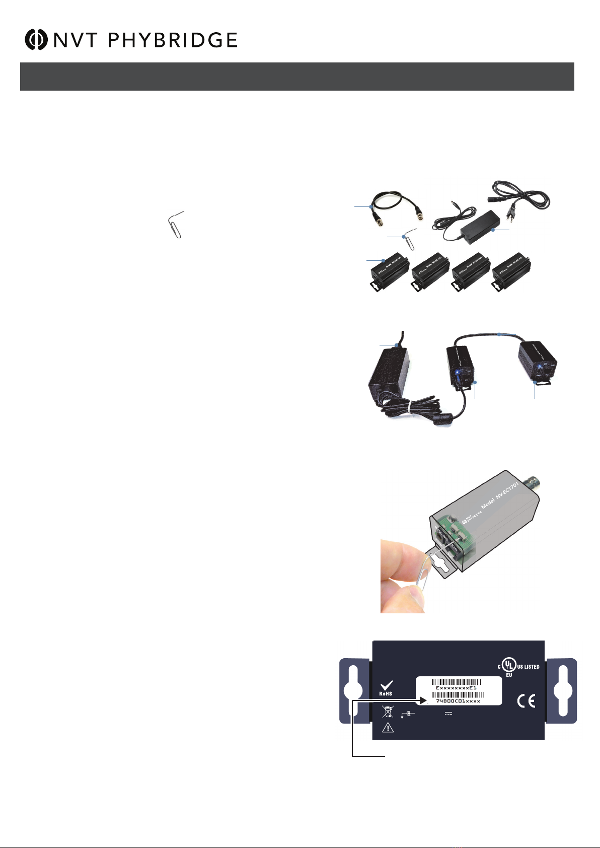
Transceivers must be configured prior to use. See page 2.
Use one NV-EC1701 transceiver at each end of the coax. Up
to four remote transceivers and coax runs may be connected
to a fifth transceiver at the control room using the
NV-EC4BNC adaptor/splitter. Multiple splitters may be used
for larger systems.
Set the NV-EC1701 PoE toggle switch (located near the BNC
connector) to ON if the connected IP device requires PoE to
be delivered by the NV-EC1701 and to OFF if PoE should not
be delivered by NV-EC1701. This setting relates to power
delivery at the Ethernet RJ45 connection.
Connect a 55VDC power supply into one of the transceivers to
provide power to the entire system, including the cameras.
Data signals over the coax are capable of extended distances,
however voltage-drop in the 55V power distribution will often
reduce this maximum, depending on the camera’s current
draw and wire resistance.
Note: Within one network, up to two power supplies may
be deployed to support extended wire distances or higher
camera loads.
INSTALLATION INSTRUCTIONS
Page 1 of 2
SAFETY WARNINGS AND PRECAUTIONS
The NVT Phybridge Model NV-EC1701 Ethernet over Coax
EoC Transceiver is a compact media converter that allows
10/100 BaseT Ethernet and PoE, PoE+, or high-power PoE to
be transmitted using coax cable. These EoC devices are
typically used in legacy installations where existing coax is
redeployed as part of an upgrade to IP cameras. 48-55VDC
class 2 power is delivered to one transceiver, which distributes
it to multiple remote transceivers, and their PoE cameras.
These transceivers are extremely simple to use, with no IP or
MAC address configuration required. Status LEDs indicate
power and link connectivity/activity for RJ45 and BNC ports.
Warranty
The NV-EC1701 is backed by NVT Phybridge’s award
winning customer support and limited lifetime warranty.
Compliance and Environmental Information
All the compliance and environmental information is available
on our website www.nvtphybridge.com
Condensed Installation Guide
View the complete guide at www.nvtphybridge.com
Ethernet over Coax EoC Transceiver
Model NV-EC1701
Cat5
≤328ft
(≤100m)
Cat5
LAN/WAN
Monitor
Hybrid
DVR or NVR
6 Watt IP Camera
≤328ft
(≤100m)
Ethernetover Coax EoC Transceiver
RG-59/U
20 AWG
Ethernetover Coax EoC Transceiver
NV-EC1701 NV-EC1701
55VDC Power Supply
1,800 ft(600 m) NEW FEATURE
NVT Phybridge
888.901.3633 | +44 (0) 208 977 6614
www.nvtphybridge.com
Copyright © 2017 NVT Phybridge
451-1701-1-H1
2019/06
• Refer to the Complete Installation Guide under "SAFETY WARNINGS" available at www.nvtphybridge.com
• Reportez-vous au Complete Installation Guide sous "SAFETY WARNINGS" disponible à www.nvtphybridge.com
• Siehe Complete Installation Guide unter "SAFETY WARNINGS" verfügbar unter www.nvtphybridge.com
• Consulte Complete Installation debajo de "SAFETY WARNINGS" disponible en www.nvtphybridge.com
• Katso Complete Installation Guide kohdassa "SAFETY WARNINGS" osoitteessa www.nvtphybridge.com
• Raadpleeg de Complete Installation Guide onder "SAFETY WARNINGS" die beschikbaar is op www.nvtphybridge.com
• Se den Complete Installation Guide under "SAFETY WARNINGS" som finns på www.nvtphybridge.com
• Se den Complete Installation Guide under "SAFETY WARNINGS", der findes på www.nvtphybridge.com
• Ανατρέξτε στο Complete Installation Guide στο "SAFETY WARNINGS" που διατίθεται στο www.nvtphybridge.com
• Fare riferimento alla Complete Installation Guide sotto "SAFETY WARNINGS" disponibile all'indirizzo www.nvtphybridge.com
• Consulte o Complete Installation Guide em "SAFETY WARNINGS" disponível em www.nvtphybridge.com
• Irreferi għall- Complete Installation Guide taħt "SAFETY WARNINGS" disponibbli f 'www.nvtphybridge.com
• Vt "SAFETY WARNINGS" all Complete Installation Guide, mis on saadaval aadressil www.nvtphybridge.com
• Lásd a Complete Installation Guide -et a "SAFETY WARNINGS" alatt a www.nvtphybridge.com címen
• Glejte Complete Installation Guide pod "SAFETY WARNINGS" na voljo na www.nvtphybridge.com
• Viz část Complete Installation Guide v části "SAFETY WARNINGS", která je k dispozici na adrese www.nvtphybridge.com
• Žiūrėkite Complete Installation Guide, esantį "SAFETY WARNINGS", esančiame www.nvtphybridge.com
• Skatiet Complete Installation Guide zem "SAFETY WARNINGS", kas pieejams vietnē www.nvtphybridge.com
• Pozrite si časť Complete Installation Guide v časti "SAFETY WARNINGS", ktorá je k dispozícii na adrese www.nvtphybridge.com
• Sjá Complete Installation Guide undir "SAFETY WARNINGS" í boði á www.nvtphybridge.com
• Informacje na ten temat znajdują się w części Complete Installation Guide pod "SAFETY WARNINGS" dostępnej pod adresem
www.nvtphybridge.com
• Se Complete Installation Guide under "SAFETY WARNINGS" tilgjengelig på www.nvtphybridge.com
• Consultați Complete Installation Guide sub "SAFETY WARNINGS" disponibil la www.nvtphybridge.com
• Обърнете се към Complete Installation Guide под "SAFETY WARNINGS" на www.nvtphybridge.com
TECHNICAL SPECIFICATIONS
Dimensions (LxWxH) 4.10 x 1.65 x 1.57” (102 x 42 x 40mm)
Weight 5.12 oz. (145 g)
RJ45 Ethernet Interface Connectivity: RJ45 auto-crossover
Wire type: CAT5 or better
Distance: Up to 328ft (100m)
Speed: 10/100 Base T, auto-negotiation auto MDI/MDIX cross-over
Latency: 3ms
Data Throughput: 85Mbps ± 10% usable bandwidth per network.
Power Output: For maximum distance, 55VDC appears on all eight RJ45 pins, and are current-protected and
transient-protected.
Coax Building Wiring
Interface
Connectivity: BNC, RG-59:U or similar
Impedance: 25 to 100 Ohm
Distance: Refer to the complete guide at www.nvtphybridge.com
Topology: Bus architecture supports star, daisy-chain, or any combination. One control-room
NV-EC1701 may support multiple remote NV-EC1701s
Transmission Technology: IEEE 1901, 128 bit AES encryption
Power Supply The AC/DC Power supply is external and has the following characteristics
Optional NVTPhybridge Power Supplies
Power Consumption ≤ 3W
Operating Temperature -40°F to 104°F (-40°C to +40° C)
Storage Temperature -40°F to 185°F (-40°C to +85° C)
Humidity 20% to 85% non-condensing
- Input: 120/240VAC, 50/69Hz
- Output: +55VDC
- Output via a molded PIJ 5.5mm barrel connector
- Model NV-PS55-60W (55VDC, 60W)
- Model NV-PS55-110W (55VDC, 110W)
CONFIGURATION INSTRUCTIONS
NV-EC1701 EoC transceivers transmit high bandwidth encrypted Ethernet signals over conventional coax cables. To provide utmost signal integrity and security, the
NV-EC1701 transceivers must be configured to communicate exclusively with other transceivers within their Network Group. This group typically consists of one
NV-EC1701 located at the control room (usually connected to an Ethernet switch or router), and multiple remote NV-EC1701 transceivers (usually connected to IP cameras).
The NV-EC1701 now comes in auto join mode for easy and quick deployments. The joining process is now only required when deploying more than 1 group of NV-EC1701 units.
When deploying more than 1 group (max 4 end points and 1 head end) you are required to factory default the groups after the first group. You must first factory default the units
in the next group so they can be joined together into a group. Follow the un-joining method listed below and once factory defaulted you can then move to Step 3 to join the newly
factory defaulted units together.
Step One: Gather Materials
●NV-EC1701 transceivers
●55V power supply & line-cord (NV-PS55-60W)
●Coax jumper
●Small paper-clip, partially straightened:
●Device labels
●IP Network Documentation Log
Step Two: Connect Hardware
●Remove and discard the “Configure Before Use” labels.
●Connect two NV-EC1701 transceivers using a coax jumper.
●Connect a 55V power supply to transceiver #1; Apply power.
●Verify that the blue POWER LED on each transceiver illuminates.
●
Before proceeding to next step, wait for any green BNC LED that came on
during start up to go off, approximately 10 seconds.
Step Three: Joining
●On transceiver #1, using the straightened paper-clip to access the small
push-button located behind and slightly above the RJ45 LED.
Firmly press and release this button.
The blue Power LED will begin blinking.
●Then firmly press and release the same push-button on transceiver #2.
The blue Power LED will begin blinking.
●Both transceivers have now entered Join Mode.
They will find each other and establish encrypted communication.
In about 10 seconds, the blue Power LEDs on both transceivers will return
to a steady on condition, 'and the green BNC LEDs will illuminate indicating
a successful join.
Step Four: Adding Transceivers (if required)
●Disconnect transceiver #2 and replace it with a new un-joined transceiver (#3, or #4, or #5).
●Repeat steps two and three to add additional transceivers to the same Network Group.
Step Five: Documentation
● Label the configured transceivers with a unique Network Group ID of your choice.
This will help you identify them after they have been deployed.
●Record this Network Group information in your IP Network Documentation Log.
This log may include essential documentation which will help you identify all
system devices during and after deployment:
Un-Joining a Transceiver
If you need to move a transceiver from one Network Group to another, it must first un-learn its
previous Network Group and be returned to an un-joined state. Do this by performing these
steps:
●Disconnect the transceiver from the old network.
● Connect a 55 VDC power supply to a transceiver.
●Wait until its green BNC LED is lit.
● Using the straightened paper-clip to access the small push-button located behind
and slightly above the RJ45.
Press and hold this button for 10-12 seconds until all of the LEDs flash.
●Release the paperclip.
●Observe that the green BNC LED goes on for ten seconds and then goes off.
Un-joining is now complete. If you are not sure that un-joining has been successful,
remove and then re-apply power, and repeat.
● Camera Number
● Camera Position/Location
● Camera Make & Model
● Camera MAC & IP Address
● Camera Login & Password
● Camera-end NVT Phybridge Transceiver MAC Address
● NVT Phybridge Transceiver Network Group Name
● Control Room NVT Phybridge Transceiver MAC Address
● Control Room Router Port Number
Condensed Installation Guide
View the complete guide at www.nvtphybridge.com
NVT Phybridge
888.901.3633 | +44 (0) 208 977 6614
www.nvtphybridge.com
Copyright © 2017 NVT Phybridge
451-1701-1-H1
2019/06
Step One: Gather Materials
Step Two: Connect Hardware
Step Five: Transceiver MAC Address
This device complies with Part 15 of the FCC Rules. Operation is subject to the
following two conditions: (1) This device must not cause harmful interference,
and (2) this device must accept any interference
received, including interference that
may cause undesired operation.
I.T.E
E344963
D O N O T E X C E E D T W O P O W E R S U P P L I E S P E R S Y S T E M
C L A S S 2 O N LY ( S E LV )
+ 48-55 VDC 0.03 MIN - 1.6A MAX
MADE IN ROK
Ethernet over Coax EoC Transceiver
NV-EC1701 transceivers
Paper-clip (slightly straightened)
Coax jumper
55V power supply
& line-cord (NV-PS55-60W)
Transceiver #1 Transceiver #2
55V power supply
& line-cord (NV-PS55-60W)
Coax jumper
Step Three:
Transparent view of push-button location
Page 2 of 2
Ethernetover Coax EoC Transceiver
Ethernet over Coax EoC Transceiver

Other NVT Phybridge Transceiver manuals

NVT Phybridge NV-EC1701 User manual

NVT Phybridge

NVT Phybridge NV-EC1701 User manual

NVT Phybridge NV-EC1701U User manual

NVT Phybridge

NVT Phybridge NV-EC1701U User manual

NVT Phybridge NV-EC1701U User manual

NVT Phybridge

NVT Phybridge NV-EC1701U User manual

Popular Transceiver manuals by other brands

Midland 77-857 owner's guide

Midland

Midland 77-857 owner's guide

Standard Communications Horizon Eclipse+ GX1250S owner's manual

Standard Communications

Standard Communications Horizon Eclipse+ GX1250S owner's manual

Vertex Standard VX-120 Alignment Guide

Vertex Standard

Vertex Standard VX-120 Alignment Guide

Icom IC-F61M instruction manual

Icom

Icom IC-F61M instruction manual

Yaesu FTM-7250DE Advance manual

Yaesu

Yaesu FTM-7250DE Advance manual

Radio Shack HTX-400 Service manual

Radio Shack

Radio Shack HTX-400 Service manual

Kenwood TK-5210 Service manual

Kenwood

Kenwood TK-5210 Service manual

Thrane&Thrane Explorer 527 Getting started

Thrane&Thrane

Thrane&Thrane Explorer 527 Getting started

Icom IC-207H Service manual

Icom

Icom IC-207H Service manual

Icom IC-H16 Service manual

Icom

Icom IC-H16 Service manual

Transition Networks E-FRL-MC03 user guide

Transition Networks

Transition Networks E-FRL-MC03 user guide

MiLAN MIL-03F installation guide

MiLAN

MiLAN MIL-03F installation guide

Olson Technology OTLT 3000 instruction manual

Olson Technology

Olson Technology OTLT 3000 instruction manual

Kenwood TM-451E instruction manual

Kenwood

Kenwood TM-451E instruction manual

Midland G 7 user manual

Midland

Midland G 7 user manual

Acrel ATC600 Operation manual

Acrel

Acrel ATC600 Operation manual

Midland Syn-Tech 70-342XL Service manual

Midland

Midland Syn-Tech 70-342XL Service manual

Chongqing Xiegu Technology X1M manual

Chongqing Xiegu Technology

Chongqing Xiegu Technology X1M manual

manuals.online logo
manuals.online logoBrands
  • About & Mission
  • Contact us
  • Privacy Policy
  • Terms and Conditions

Copyright 2025 Manuals.Online. All Rights Reserved.