manuals.online logo
Brands
  1. Home
  2. •
  3. Brands
  4. •
  5. NVT Phybridge
  6. •
  7. Transceiver
  8. •
  9. NVT Phybridge NV-EC1701U User manual

NVT Phybridge NV-EC1701U User manual

13) BNC Connection: the installation shall be in accordance
with the applicable provisions of the National Electrical Code
ANSI/NFPA 70, Article 800.90 and Canadial Electrical Code
Part 1, Section 60-504.
12) Refer all servicing to qualified service personnel.
Servicing is required when the apparatus has been damaged
in any way, such as a power supply cord or plug is damaged,
liquid has been spilled, or objects have fallen into the
appara-tus, the apparatus has been exposed to rain or
moisture, does not operate normally, or has been dropped.
This installation should be made by a qualified service person
and should conform to all local codes.
11) Only use attachments/accessories specified by the
manufacturer.
10) Protect the power cord from being walked on or pinched
particularly at plugs, convenience receptacles, and the point
where they exit from the apparatus.
9) Do not defeat the safety purpose of the polarized or
grounding-type plug. A polarized plug has two blades with
one wider than the other. A grounding type plug has two
blades and a third grounding prong. The wider blade or the
third prong are provided for your safety. If the provided plug
does not fit into your outlet, consult an electrician for replace-
ment of the obsolete outlet.
8) Do not install near any heat sources such as radiators,
heat registers, stoves or other apparatus (including DVRs)
that produce heat.
1) Read these instructions.
2) Keep these instructions.
3) Heed all warnings.
4) Follow all instructions.
5) Do not use this apparatus near water.
6) Clean only with a dry cloth.
7) Install in accordance with the manufacturer’s instructions.
Before installing, NVT Phybridge recommends
downloading and reading the complete installation
manual from www.NVTPhybridge.com.
Transceivers must be configured prior to use. See page 2.
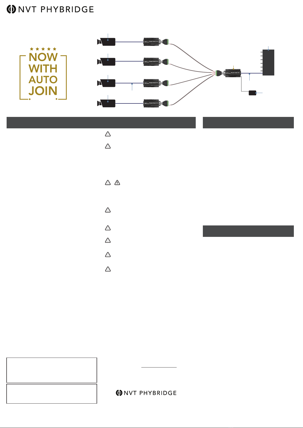
Use one NV-EC1701U transceiver at each end of the cable.
Multiple remote transceivers and cable runs may be connect-
ed to a transceiver at the control room. Torque all screw
connections to 2 in-lbs (0.2 Nm).
Set the NV-EC1701 PoE toggle switch (located near the BNC
connector) to ON if the connected IP device requires PoE to
be delivered by the NV-EC1701 and to OFF if PoE should not
be delivered by NV-EC1701. This setting relates to power
delivery at the Ethernet RJ45 connection.
Connect a 55VDC power supply into one of the transceivers to
provide power to the entire sytem, including the cameras (or
other remote IP devices).
Data signals over the coax are capable of extended distances,
however voltage-drop in the 55V power distribution will often
reduce this maximum, depending on the camera’s current
draw and wire resistance.
Note: Within one network, up to two power supplies
maybe deployed to support extended wire distances or
higher camera loads.
INSTALLATION INSTRUCTIONS
Page 1 of 2
14) RJ45 PoE connection: to be connected only to networks
or circuits that are not routed to outside plant or building.
TO REDUCE THE RISK OF ELECTRICAL SHOCK, DO
NOT REMOVE COVER OR BACK. NO USER
SERVICEABLE PARTS INSIDE. REFER SERVICING
TO QUALIFIED SERVICE PERSONNEL.
WARNING: TO REDUCE THE RISK OF ELECTRICAL
SHOCK, DO NOT EXPOSE THIS APPARATUS TO RAIN OR
MOISTURE.
This installation should be made by a qualified service
person and should conform to all local codes.
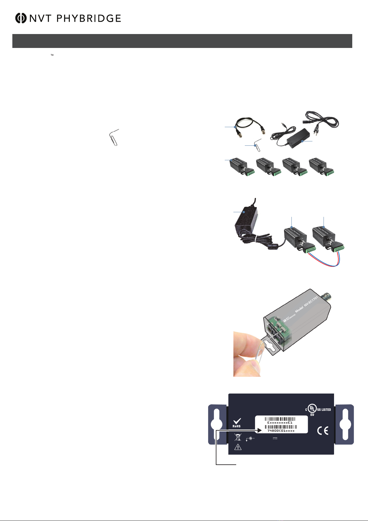
Power supplies, when provided, are external inline, with an
IEC380-C14 power inlet and 6 ft (1.8 m) line-cord. Input
Voltage is 100 ~240 VAC 50-60 Hz. A molded P1J 5.5
mm barrel connector provides a Class 2 (SELV) 48-55
VDC regulated output. Line cord UL approved type SPT-2,
SVT, or SJT, 18/3 AWG Min. 300VAC, 60° C Max. 15 ft
(4.5 m) long. One end with IEC380-C13 appliance coupler
and the other end with NEMA 1015P or equivalent for
country.
This product is intended to be supplied by a certified power
source marked “Class 2” or “LPS” and rated 48-55 VDC,
30mA minimum, 1,600mA maximum, which may or may not
be provided with the product.
Compliance and environmental information
All the compliance and environmental information is
available on our website www.nvtphybridge.com
IMPORTANT SAFETY INSTRUCTIONS PRODUCT DESCRIPTION
The NVT Model NV-EC1701U Ethernet over 2-wire
Transceiver is a compact media converter that allows 10/100
BaseT Ethernet and PoE, PoE+, or high-power PoE to be
transmitted using 2-wire cable. These devices are typically
used in legacy installations where existing cable is redeployed
as part of an upgrade to IP cameras. 48-55VDC class 2 power
is delivered to one transceiver, which distributes it to multiple
remote transceivers, and their PoE cameras (or other IP
devices).
These transceivers are extremely simple to use, with no IP or
MAC address configuration required. Status LEDs indicate
power and link connectivity/activity for RJ45 and BNC ports.
The NV-EC1701U is backed by NVT Phybridge’s award
winning customer support and limited lifetime warranty.
Condensed Installation Guide
View the complete guide at www.nvtphybridge.com
Ethernet over 2-Wire Transceiver
Model NV-EC1701U
WARNING - Do not install the unit in an environment
where the operating ambient temperature exceeds
185° F (85° C). The ventilation should not be impeded
by covering the unit with items, such as newspapers,
table-cloths, curtains, etc. No naked flame sources,
such as lighted candles should be placed on the
apparatus.
WARNING - The apparatus shall not be exposed to
dripping or splashing and no objects filled with liquids,
such as vases, shall be placed on the apparatus.
WARNING - Use only a Certified power cord and plug
(coupler / mains) assemblies for location installed.
WARNING - Power cord is regarded as main
disconnect.
WARNING - The appliance coupler (power cord/
mains) shall remain readily operable.
WARNING - For safety, never put NVT Phybridge
signals in the same conduit as high-voltage wiring.
!
!
!
!
!
!
WARNING - Do not interconnect multiple
power supply outputs. Never use more than two
power supplies within a network system. Do not
connect additional loads which would exceed the
marked output current rating of the power supply.
!
NEW FEATURE
NVT Phybridge
888.901.3633 | +44 (0) 208 977 6614
www.nvtphybridge.com
Copyright © 2017 NVT Phybridge
451-1701-1-H1
2017/05
!
Cat5
≤328ft
(≤100m)
IP Camera or Other IP Device
Ethernet over Coax EoC Transceiver
IP Camera or Other IP Device
Ethernet over Coax EoC Transceiver
IP Camera or Other IP Device
Ethernet over Coax EoC Transceiver
IP Camera or Other IP Device
Ethernet over Coax EoC Transceiver
Cat5
≤328ft
(≤100m)
Ethernet over Coax EoC Transceiver
Observe
Polarity NV-EC1701U
55VDC Power Supply
Ethernet Switch
CONFIGURATION INSTRUCTIONS
The NV-EC1701U now comes in auto join mode for easy and quick deployments. The joining process is now only required when deploying more than 1 group of NV-EC1701
units. When deploying more than 1 group (max 4 end points and 1 head end) you are required to factory default the groups after the first group. You must first factory default the
units in the next group so they can be joined together into a group. Follow the un-joining method listed below and once factory defaulted you can then move to Step 3 to join the
newly factory defaulted units together.
Step One: Gather Materials
●NV-EC1701U transceivers
●55V power supply & line-cord (NV-PS55-60W)
●Hook-up wire or BNC cable (not supplied)
●Small paper-clip, partially straightened:
●Device labels
●IP Network Documentation Log
Step Two: Connect Hardware
●Remove and discard the “Configure Before Use” labels.
●Connect two NV-EC1701U transceivers using hook-up wire or a BNC cable.
Observe polarity. Units will not power-up if the polarity is reversed.
Do not connect anything to the RJ45 connector.
●Connect a 55V power supply to transceiver #1; Apply power.
●Verify that the blue POWER LED on each transceiver illuminates.
●
Before proceeding to next step, wait for any green BNC LED that came on
during start up to go off, approximately 10 seconds.
Step Three: Joining
●On transceiver #1, using the straightened paper-clip to access the small
push-button located behind and slightly above the RJ45 LED.
Firmly press and release this button.
The blue Power LED will begin blinking.
●Then firmly press and release the same push-button on transceiver #2.
The blue Power LED will begin blinking.
●Both transceivers have now entered Join Mode.
They will find each other and establish encrypted communication.
In about 10 seconds, the blue Power LEDs on both transceivers will return
to a steady on condition, 'and the green BNC LEDs will illuminate indicating
a successful join.
Step Four: Adding Transceivers (if required)
●Disconnect transceiver #2 and replace it with a new un-joined transceiver (#3, or #4, or #5).
●Repeat steps two and three to add additional transceivers to the same Network Group.
Step Five: Documentation
● Label the configured transceivers with a unique Network Group ID of your choice.
This will help you identify them after they have been deployed.
●Record this Network Group information in your IP Network Documentation Log.
This log may include essential documentation which will help you identify all
system devices during and after deployment:
Un-Joining a Transceiver
If you need to move a transceiver from one Network Group to another, it must first un-learn its
previous Network Group and be returned to an un-joined state. Do this by performing these
steps:
●Disconnect the transceiver from the old network.
● Connect a 55 VDC power supply to a transceiver.
●Wait until its green BNC LED is lit.
● Using the straightened paper-clip to access the small push-button located behind
and slightly above the RJ45.
Press and hold this button for 10-12 seconds until all of the LEDs flash.
●Release the paperclip.
●Observe that the green BNC LED goes on for ten seconds and then goes off.
Un-joining is now complete. If you are not sure that un-joining has been successful,
remove and then re-apply power, and repeat.
● Camera Number
● Camera Position/Location
● Camera Make & Model
● Camera MAC & IP Address
● Camera Login & Password
● Camera-end NVT Phybridge Transceiver MAC Address
● NVT Phybridge Transceiver Network Group Name
● Control Room NVT Phybridge Transceiver MAC Address
● Control Room Router Port Number
Condensed Installation Guide
View the complete guide at www.nvtphybridge.com
NVT Phybridge
888.901.3633 | +44 (0) 208 977 6614
www.nvtphybridge.com
Copyright © 2017 NVT Phybridge
451-1701-1-H1
2017/05
Step One: Gather Materials
Step Two: Connect Hardware
Step Five: Transceiver MAC Address
This device complies with Part 15 of the FCC Rules. Operation is subject to the
following two conditions: (1) This device must not cause harmful interference,
and (2) this device must accept any interference
received, including interference that
may cause undesired operation.
I.T.E
E344963
D O N O T E X C E E D T W O P O W E R S U P P L I E S P E R S Y S T E M
C L A S S 2 O N LY ( S E LV )
+ 48-55 VDC 0.03 MIN - 1.6A MAX
MADE IN ROK
Ethernetover Coax EoC Transceiver
NV-EC1701U transceivers
Paper-clip (slightly straightened)
Coax jumper
55V power supply
& line-cord (NV-PS55-60W)
Page 2 of 2
Ethernet over Coax EoC Transceiver
NV-EC1701U Eo2 transceivers transmit high bandwidth encrypted Ethernet signals over conventional 2-wire cables. To provide utmost signal integrity and security, the
NV-EC1701U transceivers must be configured to communicate exclusively with other transceivers within their Network Group. This group typically consists of one
NV-EC1701U located at the control room (usually connected to an ethernet switch or router), and up to four remote NV-EC1701U transceivers (usually connected to IP
cameras or other remote IP devices).
Step Three:
Transparent view of push-button location
Ethernetover Coax EoC Transceiver
55V power supply
& line-cord (NV-PS55-60W) Transceiver #1 Transceiver #2
Observe
polarity

Other NVT Phybridge Transceiver manuals

NVT Phybridge NV-EC1701U User manual

NVT Phybridge

NVT Phybridge NV-EC1701U User manual

NVT Phybridge NV-EC1701 User manual

NVT Phybridge

NVT Phybridge NV-EC1701 User manual

NVT Phybridge NV-EC1701 User manual

NVT Phybridge

NVT Phybridge NV-EC1701 User manual

Popular Transceiver manuals by other brands

Kenwood TK-7102H Service manual

Kenwood

Kenwood TK-7102H Service manual

Kenwood TR-9130 Service manual

Kenwood

Kenwood TR-9130 Service manual

Omega MWTC-REC6 user guide

Omega

Omega MWTC-REC6 user guide

General Radiotelephone Company Super MC-IIA Operation guide

General Radiotelephone Company

General Radiotelephone Company Super MC-IIA Operation guide

Midland 70-440BP user manual

Midland

Midland 70-440BP user manual

Alcatel-Lucent OmniSwitch 6250 Guide

Alcatel-Lucent

Alcatel-Lucent OmniSwitch 6250 Guide

Radio Shack HTX-202 owner's manual

Radio Shack

Radio Shack HTX-202 owner's manual

ST Sigfox S2-LP user manual

ST

ST Sigfox S2-LP user manual

Yaesu FT-8100R Technical supplement

Yaesu

Yaesu FT-8100R Technical supplement

Ortovox 3+ manual

Ortovox

Ortovox 3+ manual

Yaesu FT-2000 - MENU MODE LIST Reference book

Yaesu

Yaesu FT-2000 - MENU MODE LIST Reference book

Alinco DR-620T instruction manual

Alinco

Alinco DR-620T instruction manual

Arec DS-MT1 user manual

Arec

Arec DS-MT1 user manual

sunair ASB-500 Installation and operation manual

sunair

sunair ASB-500 Installation and operation manual

Williams Sound DLT 100 2.0 Quick setup guide

Williams Sound

Williams Sound DLT 100 2.0 Quick setup guide

Yaesu FT-2000 - MENU MODE LIST Technical supplement

Yaesu

Yaesu FT-2000 - MENU MODE LIST Technical supplement

F.u.n.k.e. ATR833-II-BOX manual

F.u.n.k.e.

F.u.n.k.e. ATR833-II-BOX manual

Hitron CODA5 3 Series quick start guide

Hitron

Hitron CODA5 3 Series quick start guide

manuals.online logo
manuals.online logoBrands
  • About & Mission
  • Contact us
  • Privacy Policy
  • Terms and Conditions

Copyright 2025 Manuals.Online. All Rights Reserved.