O&O DAKOTA DK 210-500 Quick start guide

• DISSUASORE DI SOSTA
• NO PARKING DEVICE
• BORNE D’ARRÊT
• HALTEHEMMPFOSTEN
• SISTEMAANTI-APARCAMIENTO
INSTALLAZIONE USO E MANUTENZIONE • INSTALLATION USE AND MAINTENANCE • POSE, MODE D’EMPLOI
ET ENTRETIEN • INSTALLATION, GEBRAUCH UND WARTUNG • INSTALACIÓN USO Y MANTENIMIENTO
INTRODUZIONE
Il libretto di INSTALLAZIONE USO
E MANUTENZIONE è destinato agli
installatori, agli utilizzatori ed agli
operatori della manutenzione.
Leggere attentamente il libretto prima
di installare il prodotto, utilizzarlo e prima
di eseguire manutenzione ordinaria o
straordinaria.
Le operazioni che, possono presentare
rischi, sono indicate con i simboli:
INTRODUCTION
The INSTALLATION, USE AND
MAINTENANCE handbook is for
installers, users and maintenance
engineers.
Please read it carefully before
installing the appliance, before using
it and before routine or extraordinary
maintenance work.
Operations that, can be risky, are
indicated with the following symbols:
AVANT-PROPOS
Cette notice est destinée aux
installateurs, aux utilisateurs et aux
techniciens chargés de l’entretien.
Lisez attentivement cette notice, avant
d’installer l’automatisme, de l’utiliser
et avant de procéder à son entretien
ordinaire ou extraordinaire.
Les opérations présentant des risques
sont signalées avec les symboles :
FOLGORAZIONE SCHIACCIAMENTO
La O&O s.r.l. non è responsabile per
danni arrecati a persone, animali o cose
dovuti ad applicazioni che superano
i limiti indicati nella scheda tecnica
allegata o dall’uso diverso da quello per
cui il prodotto è stato progettato.
GENERALITA’
Il dissuasore DAKOTA è la soluzione
idealeperlagestionedeltrafficoveicolare
nel rispetto dei moderni canoni di
arredo urbano. Può essere utilizzato
per applicazioni di controlli accessi o
per tutelare aree private con la massima
sicurezza.
ELECTROCUTION CRUSHING
O&O s.r.l. is not liable for injury to
people or animals or damage to things
in the case of applications that exceed
the limits specified on the enclosed
technical data sheet or by a use
different from what the appliance has
been designed.
GENERAL
The DAKOTA deterrent bollard is the
ideal solution for managing vehicle traffic
incompliancewithmodernurbanfurnishing
requirements. It can be used to contol
entrances or to safeguard private areas
in total safety.
ELECTROCUTION ECRASEMENT
La société O&O s.r.l. décline toute
responsabilité en cas de dégâts à des
personnes, animaux ou biens provoqués
par des applications dépassant les limites
prévues dans la fiche technique jointe ou
par un usage différent de celui pour lequel
l’automatisme a été conçu.
GENERALITES
La borne escamotable DAKOTA est la
solutionidéale pour contrôlerle trafic routier
selon les concepts modernes de mobilier
urbain. Elle contrôle l’accès ou protège les
espaces privés en toute sécurité.
SCHEDA TECNICA - TECHNICAL DATA SHEET - FICHE TECHNIQUE - TECHNISCHE TABELLE - FICHA TÉCNICA
MOTORE - MOTOR - MOTEUR - MOTOR - MOTOR 230V±10% 50÷60Hz 130W 10uF 1,4 A
FREQUENZA DI LAVORO - WORKING FREQUENCY - DUREE DE L’OPERATION - EINSATZFREQUENZ - FRECUENCIA DE TRABAJO 1500/24h
GRADO DI PROTEZIONE - PROTECTION LEVEL - INDICE DE PROTECTION - SCHUTZGRAD - GRADO DE PROTECCIÓN IP67
CENTRALINA - CONTROL UNIT - CENTRALE - STEUERGERÄT - CENTRAL CDK-US
TEMP. DI ESERCIZIO • WORKING TEMPERATURE • TEMPÉRATURE D’EXERCICE • BETRIEBSTEMPERATUR • TEMPERATURA DE OPERACIÓN -15 +60 °C
TEMPO DI LAVORO - WORKING TIME - TEMPS DE TRAVAIL -ARBEITSZEIT - TIEMPO DE TRABAJO 6s. (DK Ø210-500); 9s. (DK Ø210-700)
PESO - WEIGHT - POIDS - GEWICHT - PESO 90 kg (DK Ø210-500); 110 kg (DK Ø210-700)
DIMENSIONI D’INGOMBRO • OVERALL SIZE DIMENSIONS • DIMENSIONS D’ENCOMBREMENT • RAUMBEDARF-ABMESSUNGEN
DIMENSIONES MÁXIMAS
1
45
Ø 273
700 (H=700)
490 (H=500)
185
Ø 210
Ø 355
Filo terra
Ground surface level
Sol fini
Bodenniveau
Nivel del pavimento
INTRODUCCIÓN
El folleto de INSTALACIÓN, USO
Y MANTENIMIENTO se destina a
instaladores, usuarios y operadores
de mantenimiento.
Leer detenidamente el folleto antes de
instalar el producto, utilizarlo y efectuar el
mantenimiento ordinario o extraordinario.
Las operaciones que pueden conllevar
riesgos, vienen indicadas con los
símbolos:
EINLEITUNG
Das INSTALLATIONS-, BETRIEBS-
UND WARTUNGSHANDBUCH ist
für die Installateure, Anwender und
Wartungsfachmänner bestimmt.
Das Handbuch ist vor der Installation
des Produkts sowie vor der ordentlichen
und außerordentlichen Wartung
sorgfältig zu lesen. Die Eingriffe wie
zu Gefahrsituationen können kommen,
sind gekennzeichnet durch folgende
Symbole:
STROMSCHLAG QUETSCHUNG
Die Firma O&O s.r.l. haftet nicht für Perso-
nen-, Tier- oder Sachschäden, die auf eine
unsachgemäße Anwendung des Produkts
sowie auf das Überschreiten der im tech-
nischen Blatt angegebenen Grenzwerte
zurückzuführen sind.
ALLGEMEINES
Der versenkbare Poller DAKOTA ist die ideale
Lösung zum Verwalten des Straßenverkehrs unter
Berücksichtigung der modernen Stadteinrichtung.
DerPollerkannunterGewährleistungdermaximalen
Sicherheit für die Zufahrtskontrolle oder zum
AbsperrenvonPrivatbereichenverwendetwerden.
ELECTROCUCIÓN APLASTAMIENTO
La O&O s.r.l. no es responsable de
daños causados a personas, animales
o cosas, debidos a aplicaciones que
superen los límites indicados en la ficha
técnica adjunta o debidos a utilización
diferente de aquella apra la cual el
producto fue proyectado.
GENERALIDAD
EldisuasorDAKOTAeslasoluciónideal
para la gestión del tráfico de vehículos
respetando los modernos cánones del
mobiliario urbano. Se puede utilizar para
aplicaciones de control de accesos o para
proteger áreas privadas con la máxima
seguridad.
DAKOTA IT FR ESDEEN
1175 (H=700)
915 (H=500)
DK Ø210-500 DK Ø210-500 LIGHTS
DK Ø210-700 DK Ø210-700 LIGHTS
www.torautomatic.hr

1) Linea Monofase H05VV-F 2 x 1,5 + T
2) Ricevitore 4 x 0,5
3) Pulsantiera 4 x 0,5
4) Lampeggiante 2 x 0,5
5) Selettore a chiave 2 x 0,5
6) DAKOTA Cavo in dotazione
7) Rivelatore magnetico RG58
8) Fotocellula trasmettitore 2 x 0,5
9) Fotocellula ricevitore 4 x 0,5
10) Semaforo 3 x 0,5 + T
1) Single-phase line H05VV-F 2 x 1,5 + E
2) Receiver 4 x 0,5
3) Push button panel 4 x 0,5
4) Flasher 2 x 0,5
5) Key selector 2 x 0,5
6) DAKOTA Cable supplied by us
7) Detector-Request istruction RG58
8) Trasmitter photocell 2 x 0,5
9) Receiver photocell 4 x 0,5
10) Traffic light 3 x 0,5 + E
1) Einphasenleitung H05VV-F 2 x 1,5 + E
2) Empfänger 4 x 0,5
3) Druckknopftafel 4 x 0,5
4) Blinkleuchte 2 x 0,5
5) Schlüsselschalter 2 x 0,5
6) DAKOTA Kabel beigestellt
7) Magnetdetektor RG58
8) Senderfotozelle 2 x 0,5
9) Empfängerfotozelle 4 x 0,5
10) Ampel 3 x 0,5 + E
1) Linea monofàsica H05VV-F 2 x 1,5 + T
2) Receptor 4 x 0,5
3) Botonera 4 x 0,5
4) Indicador intermitente 2 x 0,5
5) Selector de llave 2 x 0,5
6) DAKOTA Cable incluido
7) Detector magnético RG58
8) Fotocèlula transmisor 2 x 0,5
9) Fotocèlula receptor 4 x 0,5
10) Semáforo 3 x 0,5 + T
1) Ligne monophasèe H05VV-F 2 x 1,5 + T
2) Rècepteur 4 x 0,5
3) Console 4 x 0,5
4) Clignotant 2 x 0,5
5) Sèlecteur à clè 2 x 0,5
6) DAKOTA Cable fourni en dotation
7) Dètecteur magnètique RG58
8) Photocellule èmettrice 2 x 0,5
9) Photocellule rèceptrice 4 x 0,5
10) Feu tricolore 3 x 0,5 + T
3
NOTA CAVI • WIRING NOTE • BRANCHEMENTS • BEMERKUNG ZU DEN KABEL ANSCHLÜSSEN • NOTA CABLES
200
1100
915
AB
C
D
E
F
G
H
1300
A) Asfalto
B) Cemento
C) Guaina Ø50
D) Sabbia compatta
E) Ø800 x 1000 H
F) Sabbia fine
G) Ghiaia
H) Drenaggio Ø125
DISPOSIZIONE • LAYOUT • DISPOSITION • LAYOUT • DISPOSICIÓN
2
A) Road surface
B) Cement
C) Sheathing Ø50
D) Compact sand
E) Ø800 x 1000 H
F) Fine sand
G) Pebble gravel
H) Drainage Ø125
A) Asphalte
B) Ciment
C) Gaine Ø50
D) Sable compact
E) Ø800 x 1000 H
F) Sable fin
G) Gravier
H) Drainage Ø125
A) Asfalto
B) Cemento
C) Vaina Ø50
D) Arena compacta
E) Ø800 x 1000 H
F) Arena fina
G) Gravilla
H) Drenaje Ø125
A) Asphalt
B) Zement
C) Anschluss Ø50
D) Verdichtetetsand
E) Ø800 x 1000 H
F) Feiner sand
G) Kies
H) Drainage Ø125
1000
DK Ø210-500
AB
C
D
E
F
G
H
200
1400
1175
1250
DK Ø210-700

4
FONDAZIONE • FOUNDATION • FONDATION • FUNDAMENT • FOSA
min. 1400 mm (H=700)
min. 1300 mm (H=500)
1200
1200
5
DRENAGGIO • DRAINAGE • DRAINAGE
DRAINAGE • DRENAJE
POSA TUBO IN CEMENTO • LAYING THE CEMENT TUBE
POSE TUBE EN CIMENT • LEGEN DES ZEMENTROHRS
COLOCACIÓN TUBO DE CEMENTO
915
Sabbia fine
Fine sand
Sable fin
Feiner sand
Arena fina
INSTALLAZIONE DISSUASORE • INSTALL BOLLARD • INSTALLATION DE BORNE • INSTALL POLLER
INSTALLACIÓN DISUASOR
DRENAGGIO • DRAINAGE • DRAINAGE
DRAINAGE • DRENAJE POSA TUBO IN CEMENTO • LAYING THE CEMENT TUBE
POSE TUBE EN CIMENT • LEGEN DES ZEMENTROHRS
COLOCACIÓN TUBO DE CEMENTO
1175
Sabbia fine
Fine sand
Sable fin
Feiner sand
Arena fina
DK Ø210-500DK Ø210-700

POSIZIONARE IL DISSUASORE • FIT THE BOLLARD
POSITIONNER LA BORNE • DEN POLLER EINSETZEN
COLOCAR EL POSTE
COMPLETARE LA PAVIMENTAZIONE
FLOORING COMPLETION
COMPLETER LE SOL
DEN BODENBELAG FERTIGSTELLEN
TERMINAR EL PAVIMENTO
Senso di marcia
Running direction
Sens de marche
Fahrtrichtung
Dirección de marcha
6
COLLEGAMENTI ELETTRICI • ELECTRICAL CONNECTIONS • BRANCHEMENTS ELECTRIQUES
ELEKTRISCHE ANSCHLÜSSE • CONEXIONES ELÉCTRICAS
CDK-US

MESSA IN FUNZIONE • STARTING THE DEVICE
MISE EN SERVICE • INBETRIEBNAHME
PUESTA EN FUNCIONAMENTO
7
8SBLOCCO D’EMERGENZA • HAND MANOEUVRE
MANOEUVRE MANUELLE • MANUELLE BETÄTIGUNG
MANIOBRA MANUAL
9
VERIFICA CONCENTRICITA’ STELO • CHECK THE CONCENTRICITY OF THE BOLLARD • CONTROLE CONCENTRICITE
PLOT • DIE KONZENTRIZITÄT DES SCHAFTS PRÜFEN • COMPROBACIÓN CONCENTRICIDAD COLUMNA
Concentricità stelo OK.
Bollard concentricity OK.
Concentricité plot OK.
Schaftkonzentrizität OK.
Concentricidad columna OK.
OK NO
Regolare la concentricità dello stelo (punto 13)
Adjust the concentricity of the bollard (point 13)
Régler la concentricité du plot (point 13)
Die Schaftkonzentrizität einstellen (Punkt 13)
Ajustar la concentricidad de la columna (punto 13)
Rimuovere l’anello di protezione in
gomma
Remove the rubber ring
Retirer l’anneau de protection en caou-
tchouc
Den schutzring aus gummi entfernen
Quitar el anillo de protección de goma
Interrompendo l’alimentazione elettrica il dissuasore scende sponta-
neamente.
The deterrent bollard lowers spontaneously when you disconnect the
power supply.
Lorsque l’alimentation électrique est coupée, la borne s’abaisse auto-
matiquement.
Bei Unterbrechen der Stromversorgung wird der Poller automatisch
versenkt.
Cortando la alimentación eléctrica la columna baja espontáneamente.
Start
10
REGOLAZIONE CONCENTRICITA’ • CONCENTRICITY ADJUSTMENT• REGLAGE CONCENTRICITE
KONZENTRIZITÄTSEINSTELLUNG • REGULACIÓN CONCENTRICIDAD’
Regolare la concentricità dello stelo
Adjust the concentricity of the bollard
Régler la concentricité du plot
Die Schaftkonzentrizität einstellen
Ajustar la concentricidad de la columna
Bloccare la posizione avvitando i 4 grani
Block the position by screwing the 4 nuts
Bloquer la position en vissant les 4 goujons
Den Schaft mit den 4 Stiften blockieren.
Bloquear la posición apretando los 4 prisio-
neros
Svitare e togliere i quattro grani M8
Unscrew and remove the four nuts M8
Dévisser et enlever les quatre goujons M8
Die vier Stifte M8 abschrauben und entfernen
Desenroscar y sacar los 4 prisioneros M8

COD. 035345 rev. 000 del 22/03/10
O&O s.r.l. - Via Europa, 2 - 42015 CORREGGIO (R.E.) Italy
tel. +39 (0)522 740111 - fax +39 (0)522 631290
http://www.oeo.it - email: oeo@oeo.it
Società soggetta ad attività di direzione e coordinamento di SOMFY S.A.
Company subject to management and coordination activities by SOMFY S.A.
SICUREZZA GENERALE
• Siconsiglia, per ragioni disicurezza
enelrispettodellenormativevigenti,
di utilizzare l’apposita centralina di
comando O&O.
• L’installazionedeveessereeseguita
seguendo le prescrizioni contenute
nel foglio allegato “AVVERTENZE
GENERALI PER LA SICUREZZA”.
• I collegamenti elettrici devono
essere effettuati nel rispetto delle
disposizioni legislative vigenti.
• L’installatoredeveistruirel’utilizzatore
sul corretto funzionamento
dell’automatismo, sulla manovra
manualed’emergenzaesuipossibili
rischi durante il funzionamento.
• Eseguire l’analisi dei rischi
prendendoopportuniprovvedimenti
per eliminarli, come prescritto dalla
direttiva macchine 2006/42/CEE,
installando i dispositivi di sicurezza.
• Prima di effettuare qualsiasi
intervento sull’impianto togliere
l’alimentazione elettrica mediante
un sezionatore lucchettabile.
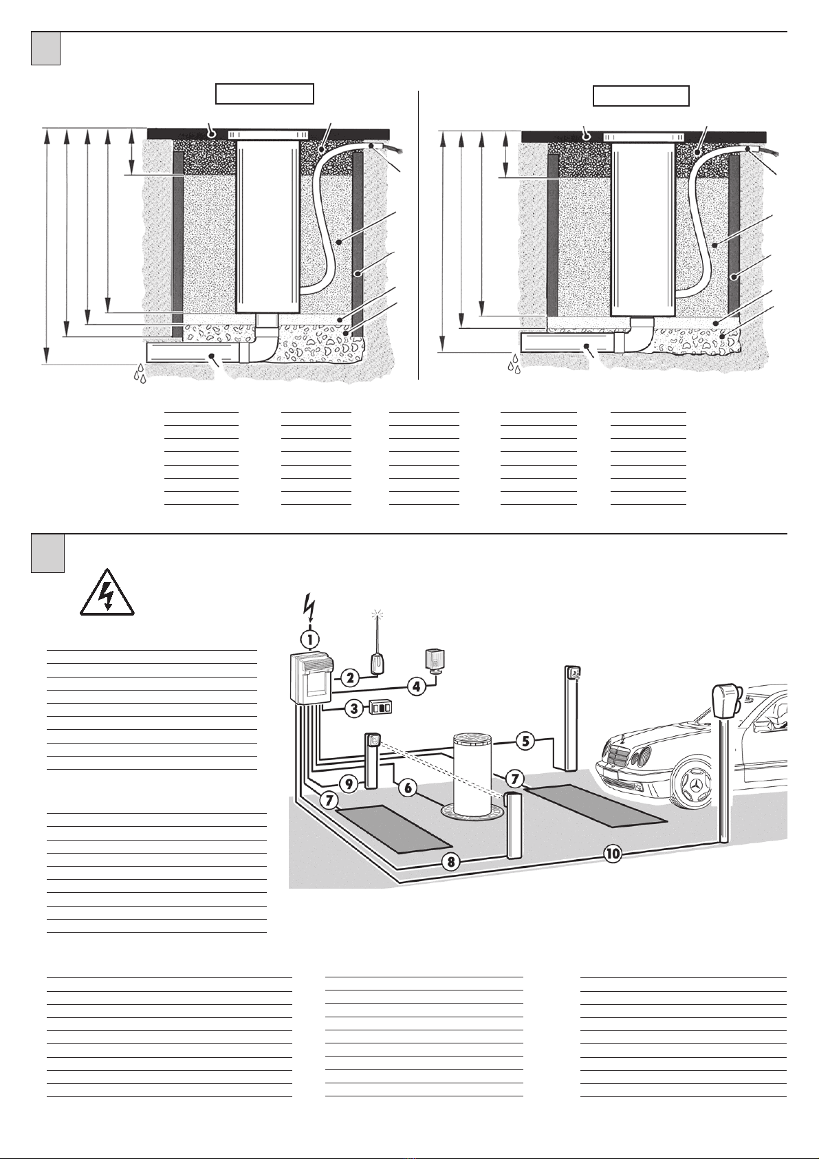
USO
• Consultareilmanualed’installazione
e uso della centralina CDK-US.
• Pereffettuarelosbloccod’emergenza
seguire le indicazioni descritte al
punto 8.
MANUTENZIONE
ORDINARIA
(OGNI SEI MESI)
• La manutenzione deve essere
eseguita solo da personale
qualificato.
• Controllare visivamente lo stato
generalediconservazionedelleparti
esterne del dissuasore.
• Controllare che la pellicola
retroriflettentedelcappelloluminoso
non sia usurata.
•
Controllare la funzionalità delle
luci.
• Controllare la concentricità dello
stelo
• Controllare il funzionamento della
manovra di emergenza.
• Controllare il funzionamento della
centralina e dei dispositivi di
sicurezza.
GENERAL SAFETY
• Forsafetyreasonsandtocomplywith
current standards, we recommend
using the O&O control unit.
• To install follow the instructions
given in the enclosed “GENERAL
INSTRUCTIONS FOR SAFETY”
sheet.
• All electrical connections must be
doneincompliancewithcurrentlaws.
• The installer must instruct the user
on how to use the automatism
correctly,on the manualemergency
manoeuvreandonthepossiblerisks
during operation.
• Analyse the risks and take all the
appropriate measures to eliminate
them, as prescribed by the EEC
machinedirective2006/42,installing
the safety devices.
• Always disconnect the electricity
before attempting any work on the
systemwithalockablecut-offswitch.
USE
• Consult the CDK-US control unit’s
installation and operating manual.
• Followtheinstructionsgiveninpoint
8toreleaseinthecaseofemergency.
ROUTINE
MAINTENANCE
(EVERY 6 MONTHS)
• Maintenancemustbecarriedoutby
qualified personnel only.
• Visually check the overall state of
wear and tear of the external parts
of the deterrent bollard.
• Make sure the rear-reflecting film of
the luminous hood is not worn.
•
Make sure the lights work.
• Checktheconcentricityofthebollard.
• Make sure the emergency
manoeuvre is working properly.
•Makesurethecontrolunitandsafety
devicesare in proper workingorder.
SECURITE GENERALE
• Pour des raisons de sécurité et
d’observation de la législation en
vigueur, il est conseillé d’utiliser la
centrale de commande O&O.
• La pose doit s’effectuer selon les
prescriptionsreportéessurlafeuille
jointe “REGLES GENERALES DE
SECURITE”.
• Les branchements électriques
doivent être conformes à la
législation en vigueur en la matière.
• L’installateur doit informer
l’utilisateur sur le fonctionnement
del’automatisme,surla manœuvre
manuelled’arrêtd’urgenceetsurles
risques liés au fonctionnement.
• L’analyse des risques implique la
misesurpieddemesuresdestinées
à éliminer lesdits risques comme
le prévoit la directive machines
2006/42/CEE, en installant les
dispositifs de sécurité.
• Coupez l’arrivée de courant
électrique avant toute intervention
sur l’automatisme avec un
interrupteur verrouillable.
UTILISATION
• Consulterlemanueld’installationet
d’utilisation de la centrale CDK-US.
• Pour effectuer la manoeuvre
manuelle, suivez les indications du
point 8.
ENTRETIEN
ORDINAIRE
(TOUS LES 6 MOIS)
• L’entretien doit être effectué
seulementpar un personnel qualifié.
• Vérifier visuellement l’état général
des parties externes de la borne.
• Vérifier que la pellicule rétro-
réfléchissantedelapartiesupérieure
n’est pas usée.
•
Vérifier le bon fonctionnement
des lumières.
• Vérifierqueleplotestconcentrique.
• Vérifier le fonctionnement de la
manœuvre d’arrêt d’urgence.
• Vérifier le fonctionnement de la
centraleetdesdispositifsdesécurité.
ALLGEMEINE SICHERHEIT
•
Aus Sicherheitsgründen und zum
Einhalten der anwendbaren Gesetze
wird empfohlen, die spezielle
SteuereinheitvonO&Ozuverwenden.
• Bei der Installation sind die im
beiliegenden Blatt “ALLGEMEINE
SICHERHEITSHINWEISE”
enthaltenen Vorschriften zu befolgen.
• BeimAnschlussandieStromversorgung
sind die geltenden Gesetze zu
befolgen.
• Der Installateur hat den Anwender
bezüglich des korrekten Betriebs
des Automatismus, der manuellen
BedienungbeiStörungenundNotfällen
sowie bezüglich der möglichen
Gefahren während des Betriebs zu
unterrichten.
• Es ist eine Gefahrenanalyse
durchzuführen und es sind geeignete
Maßnahmen zum Eliminieren der
Gefahren zu treffen, wie von der
Maschinenrichtlinie 2006/42/EWG
vorgeschrieben,wobeiauchderSchub
einreguliert und die erforderlichen
Sicherheitsvorrichtungen installiert
werden müssen.
• Vor jeglichenEingriffen anderAnlage
ist die Stromversorgung mit einen
Schlüssel-Trennschalter zu unterbrechen.
SEGURIDAD GENERAL
• Por razones de seguridad y para
respetar las normas vigentes se
aconseja utilizar la correspondiente
centralita de control O&O.
• La instalación debe efectuarse
siguiendo las prescripciones
presentadas en la hoja
adjunta“ADVERTENCIAS
GENERALES PARA LA
SEGURIDAD”.
• Las conexiones eléctricas deben
efectuarse cumpliendo las
disposiciones de ley vigentes.
• Elinstalador debe instruir alusuario
sobre el funcionamiento correcto
del automatismo, maniobra manual
de emergencia y posibles riesgos
durante el funcionamiento.
• Efectuar el análisis de riesgos
tomando las oportunas medidas
para eliminarlos, como prescrito
por la directiva máquina 2006/42/
CEE, instalando los dispositivos de
seguridad.
• Antes de cualquier operación en la
instalación, cortar la alimentación
eléctrica con un interruptor
seccionador.
USO
• Consultar el manual de instalación
y uso de la centralita CDK-US.
• Para efectuar el desbloqueo de
emergencia seguir las indicaciones
del punto 8.
MANTENIMIENTO
ORDINARIO
(CADA 6 MESES)
• El mantenimiento debe ser
efectuado sólo por personal
cualificado.
• Comprobar visualmente el estado
general de las partes externas del
disuasor.
• Comprobar que la película
retrorreflectora de la caperuza
luminosa no está gastada.
•
Comprobar la funcionalidad de
las luces.
• Comprobar la concentricidad de la
columna.
• Comprobar el funcionamiento de la
maniobra de emergencia.
• Comprobar el funcionamiento de la
centralita y de los dispositivos de
seguridad.
BETRIEB
•
Die Installations und
Bedienungsanleitungen
der Steuereinheit CDK-US
nachschlagen.
• Für die manuelle Betätigung in
Notfällen sind dieAnleitungen unter
Punkt 8zu befolgen.
ORDENTLICHE
WARTUNG
(ALLE 6 MONATE)
• Die Wartung hat ausschließlich durch
Fachpersonal zu erfolgen.
• Die Außenteile des Pollers
einer allgemeinen Sichtkontrolle
unterziehen, um Beschädigungen
festzustellen.
• Kontrollieren, dass die
Rückstrahlfolie des Leuchtkopfes
nicht verschlissen ist.
• Die Funktionstüchtigkeit der
Leuchten kontrollieren.
• Die Konzentrizität des Schafts
überprüfen.
• Kontrollieren, dass die manuelle
Notfall-Manövriervorrichtung
einwandfrei funktioniert.
• Die Funktionstüchtigkeit
der Steuereinheit und der
Sicherheitsvorrichtungen
überprüfen.
Croatia: Distribution & Support
www.torautomatic.hr
This manual suits for next models
1
Table of contents
Other O&O Automatic Barrier manuals
Popular Automatic Barrier manuals by other brands

CAME
CAME G2080EZC Installation and operation manual

AMC
AMC FLEX 500 - 2000 Installation handbook

CAME
CAME GARD series installation manual

Nice
Nice LBar Instructions and warnings for installation and use

Riello Elettronica
Riello Elettronica CARDIN CDR 861 manual

BFT
BFT MAXIMA 30 Instructions for installation, use and maintenance