O&O NIGHT&DAY.6 Parts list manual

UNAC
ASSOCIAZIONE COSTRUTTORI
DI INFISSI MOTORIZZATI E AUTOMATISMI
PER SERRAMENTI IN GENERE
NIGHT&DAY.6
NIGHT&DAY.8
Istruzioni per installazione uso e manutenzione
Instructions for installation, use and maintenance
Instructions d’installation et d’entretien
Installations, Gebrauchs und Wartungsanleitungen
Instrucciones para la instalación, el uso y el mantenimiento
Barriera automatica
Automatic barrier
Barrière automatique
Automatische Schranke
Barrera automática ES
DE
FR
EN
IT

DICHIARAZIONE “CE” DI CONFORMITA’
“CE” DECLARATION OF CONFORMITY
Il costruttore: O&O Srl
The manufacter:
Indirizzo: Via Europa 2 - 42015 Correggio (RE)
Address:
DICHIARA CHE IL SEGUENTE APPARATO
DECLARES THAT THE FOLLOWING EQUIPMENT
Descrizione: Barriera elettromeccanica automatica
Description: Automatic electromechanical barriers
Modello - Model: NIGHT&DAY.3 NIGHT&DAY.DD3 NIGHT&DAY.5 NIGHT&DAY.6 NIGHT&DAY.8
NIGHT&DAY.SPEED NIGHT&DAY.5 XT
- Risulta conforme con quanto previsto dalle seguenti Direttive Comunitarie, comprese le ultime modiche e con la legislazione nazionale
di recepimento:
IsinconformitywiththeprovisionsofthefollowingCommunityDirectives,includingthelatestmodicationsandwiththeassimilatingnational
legislation:
2004/108/CEE; 93/68/CEE ( EN61000-6-3 (2003); EN61000-6-2 (2003))
Compatibilità Elettromagnetica • Electromagnetic Compatibility
2006/95/CEE; 93/68/CEE ( EN60204-1 (2006))
Bassa tensione•Lowvoltage
99/5/CEE ( ETSI EN 301 489-3 (2002) + ETSI EN 301 498-1 (2005); ETSI EN 300 220-2 (2006))
Apparecchiatura radio•Radioset
2006/42/CEE ( EN60204-1 (2006))
Direttiva macchine•Machinerydirective
L’apparato è stato testato con la centralina elettronica CSB-BR (N&D.3 - N&D.5 - N&D.6 - N&D.8), ARX.DD3 (N&D.DD3), CSB-SP
(N&D.SPEED) e CSB-XT (N&D.5 XT) nella congurazione tipica di installazione.
The equipment has been tested with the electronic control unit CSB-BR (N&D.3 - N&D.5 - N&D.6 - N&D.8), ARX.DD3 (N&D.DD3), CSB-SP
(N&D.SPEED) and CSB-XT (N&D.5 XT)inthetypicalinstallationconguration.
O&O S.r.l.
Via Europa, 2 - 42015 Correggio (RE) Italy
Tel. +39 0522 740111 - Fax +39 0522 631290
AZIENDACERTIFICATAUNIENISO9001:2008
COMPANYWITHQUALITYSYSTEMCERTIFIEDUNIENISO9001:2008
SocietàsoggettaadattivitàdidirezioneecoordinamentodiBFTS.p.A.
CompanysubjecttomanagementandcoordinationactivitiesbyBFTS.p.A.
ver.6
Correggio, 15/01/13 Il Rappresentante legale - The legal Representative
Stefano Valzania

3
ITALIANO ENGLISH FRANÇAIS DEUTSCH ESPAÑOL
1. Informazioni generali
1.1 Introduzione................................................ pag. 4
1.2 Sicurezza generale .................................... pag. 4
1.3 Generalità................................................... pag. 4
1.4 Dati tecnici ................................................. pag. 4
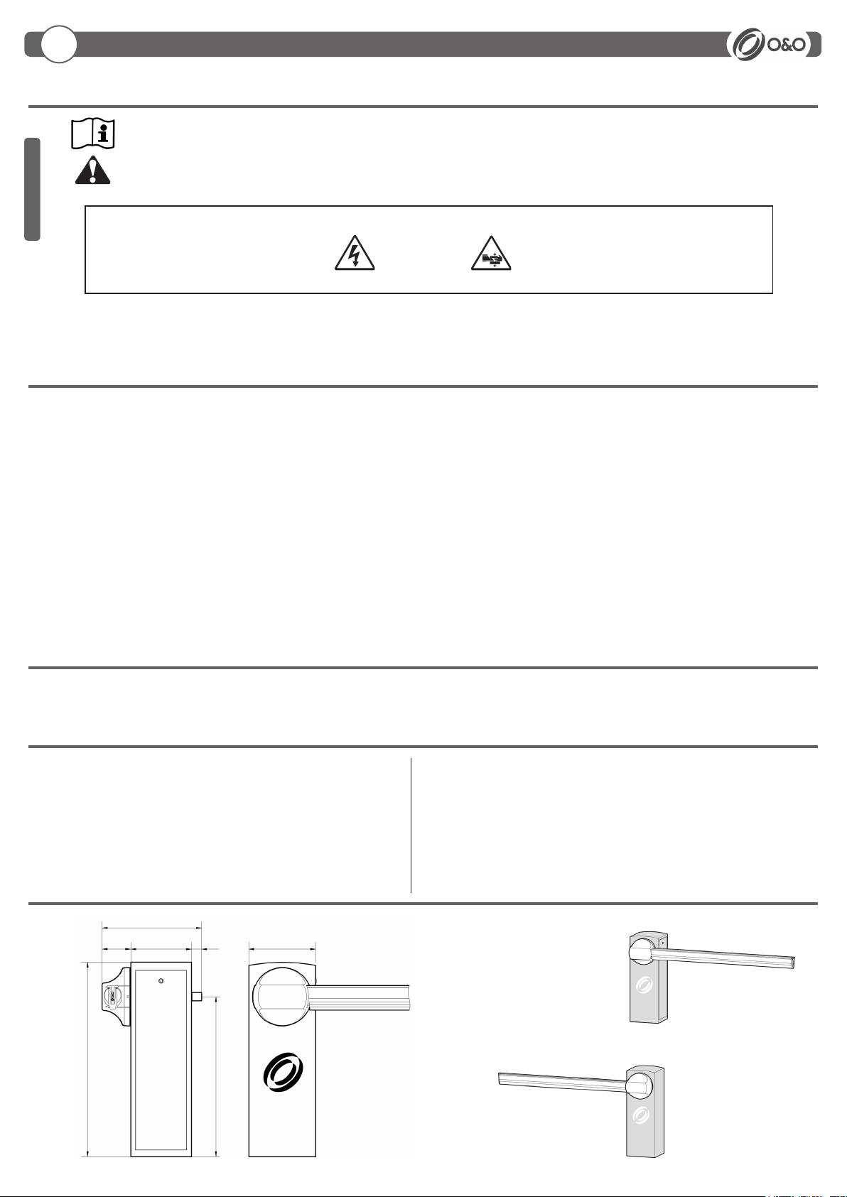
1.5 Dimensioni di ingombro............................. pag. 4
2. Installazione
2.1 Nota cavi.................................................... pag. 5
2.2 Fissaggio struttura ..................................... pag. 5
2.3 Installazione barra...................................... pag. 5
2.4 Allineamento barra..................................... pag. 6
2.5 Manovra manuale ...................................... pag. 6
2.6 Optionals .................................................... pag. 6
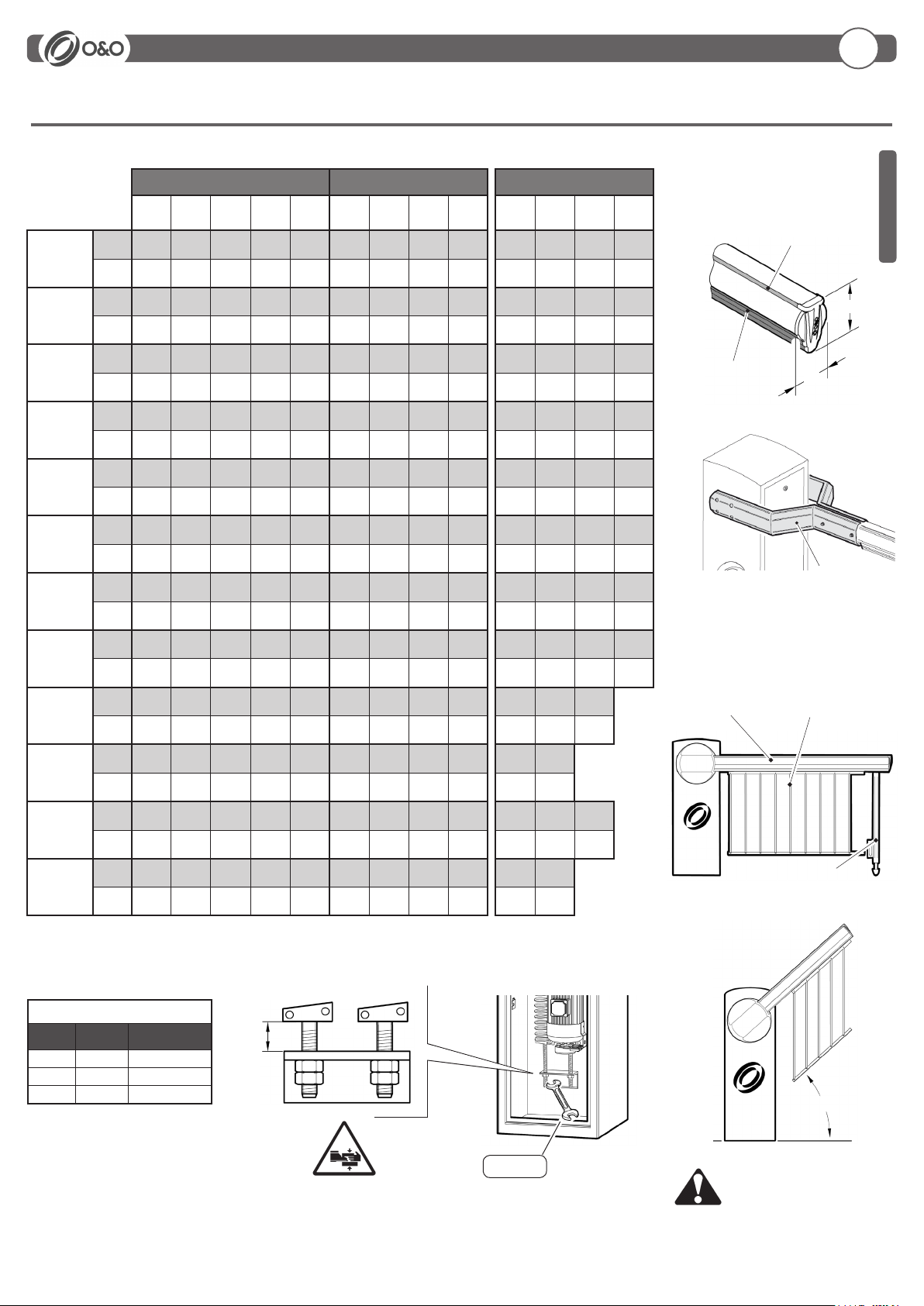
2.7 Equilibratura barra ..................................... pag. 7
3. Uso e manutenzione
3.1 Sicurezza generale .................................... pag. 8
3.2 Avvertenze ................................................. pag. 8
3.3 Uso............................................................. pag. 8
3.4 Manutenzione ordinaria ............................. pag. 8
Indice
Index
Index
Verzeichnis
Índice
1. General information
1.1 Introduction................................................. pag. 9
1.2 General safety............................................ pag. 9
1.3 General....................................................... pag. 9
1.4 Technical specication ............................... pag. 9
1.5 Overall dimensions .................................... pag. 9
2. Installation
2.1 Cable note ................................................. pag.10
2.2 Fixing the structure.................................... pag.10
2.3 Instal the arm............................................. pag.10
2.4 Align the arm ............................................. pag.11
2.5 Manual manoeuvre .................................... pag.11
2.6 Optionals .................................................... pag.11
2.7 Balancing the arm ..................................... pag.12
3. Use and maintenance
3.1 General safety............................................ pag.13
3.2 Warnings .................................................... pag.13
3.3 Use............................................................. pag.13
3.4 Routine maintenance ................................. pag.13
1. Informtion generales
1.1 avant-propos .............................................. pag.14
1.2 Securite generale....................................... pag.14
1.3 Generalities ................................................ pag.14
1.4 Données techniques .................................. pag.14
1.5 Dimensions hors-tout ................................. pag.14
2. Installations
2.1 Connexion cables ...................................... pag.15
2.2 Fixation structure ....................................... pag.15
2.3 Installation de la lisse................................ pag.15
2.4 Alignement de la lisse............................... pag.16
2.5 Manoeuvre manuelle ................................. pag.16
2.6 Optionals .................................................... pag.16
2.7 Equilibrage de la lisse............................... pag.17
3. Utilisation et maintenance
3.1 Sécurité générale....................................... pag.18
3.2 Avertissements........................................... pag.18
3.3 Utilisation.................................................... pag.18
3.4 Routine maintenance ................................. pag.18
1. Allgemeine informationen
1.1 Einleitung.................................................... pag.19
1.2 Allgemeine sicherheitshinweise ................. pag.19
1.3 Allgemeines................................................ pag.19
1.4 Technische daten....................................... pag.19
1.5 Abmessungen ............................................ pag.19
2. Installation
2.1 Bemerkung zu den kabel anschlüssen ..... pag.20
2.2 Strukturbefestigung .................................... pag.20
2.3 Installation des baums............................... pag.20
2.4 Die schranke ausrichten............................ pag.21
2.5 Manuelles manövrieren.............................. pag.21
2.6 Optionals .................................................... pag.21
2.7 Ausbilancierung des baumes .................... pag.22
3. Gebrauchs und Wartungsanleitungen
3.1 Allgemeine sicherheit................................. pag.23
3.2 Hinweise..................................................... pag.23
3.3 Betrieb........................................................ pag.23
3.4 Ordentliche wartung................................... pag.23
1. Informaciones generales
1.1 Introducción................................................ pag.24
1.2 Seguridad general...................................... pag.24
1.3 Generalidad................................................ pag.24
1.4 Datos técnicos ........................................... pag.24
1.5 Medidas...................................................... pag.24
2. Instalación
2.1 Nota cables................................................ pag.25
2.2 Fijación estructura...................................... pag.25
2.3 Instalación de la barra............................... pag.25
2.4 Alinear la barra.......................................... pag.26
2.5 Maniobra manual ....................................... pag.26
2.6 Optionals .................................................... pag.26
2.7 Equilibrado de la barra.............................. pag.27
3. Uso y mantenimiento
3.1 Seguridad general...................................... pag.28
3.2 Advertencias............................................... pag.28
3.3 Uso............................................................. pag.28
3.4 Mantenimiento ordinario ............................ pag.28

4
1.5 DIMENSIONI D’INGOMBRO
590
360 60 400
950
1155
170
Barriera DESTRA
Barriera SINISTRA
1.1 INTRODUZIONE
Leggere attentamente il libretto prima di installare il prodotto, utilizzarlo e prima di eseguire manutenzione ordinaria o straordinaria.
Le indicazioni precedute da questo simbolo contengono informazioni di particolare importanza, il loro mancato rispetto
può comportare la perdita della garanzia contrattuale.
LE OPERAZIONI CHE EFFETTUATE IN MODO NON CORRETTO POSSONO PRESENTARE RISCHI SONO INDICATE CON I SIMBOLI:
FOLGORAZIONE SCHIACCIAMENTO
Il libretto di INSTALLAZIONE USO E MANUTENZIONE è destinato agli installatori, agli utilizzatori ed agli operatori della manutenzione.
La Ditta non è responsabile per danni arrecati a persone, animali o cose dovuti ad applicazioni che superano i limiti indicati nella scheda
tecnica allegata o dall’uso diverso da quello per cui il prodotto è stato progettato.
1.4 DATI TECNICI
Alimentazione............................................................................. 230Vac ±10%50/60Hz
Motore ........................................................................... 230Vac 900RPM 14uF 0.11kW
Potenza assorbita .................................................................................................. 300W
Centralina .......................................................................................................... CSB-BR
Sicurezza all’urto...............................................................................................Reverser
Tempo di apertura....................................................................................................... 8s
Lunghezza barra ...................................................4÷6.4 m (N&D.6) 6.5÷8 m (N&D.8)
Temp. di esercizio......................................................................................... -30 +60°C
Manovre in 24h....................................................................................................... 2000
Grado di protezione ............................................................................................... IP 65
Peso ................................................................................................................... ~110 kg
1.3 GENERALITÀ
La barriera automatica elettromeccanica NIGHT&DAY6-8 è stata progettata per gestire passaggi con luce no a 8 metri nel rispetto delle normative
europee. Adatta ad un utilizzo di tipo industriale è la soluzione ideale per la gestione del trafco veicolare.
1.2 SICUREZZA GENERALE
• Smaltire i materiali di imballo (plastica, cartone, polistirolo, ecc.) secondo quanto previsto dalle norme vigenti. Non lasciare buste di nylon e polistirolo a
portata dei bambini.
• La Ditta declina qualsiasi responsabilità derivante dall’uso improprio o diverso da quello per cui è destinato ed indicato nella presente documentazione.
• Non installare il prodotto in atmosfera esplosiva.
• Togliere l’alimentazione elettrica, prima di qualsiasi intervento sull’impianto. Scollegare anche eventuali batterie tampone se presenti.
• Prevedere sulla rete di alimentazione dell’automazione, un interruttore o un magnetotermico onnipolare con distanza di apertura dei contatti uguale o superiore
a 3,5 mm.
• Vericare che a monte della rete di alimentazione, vi sia un interruttore differenziale con soglia da 0,03A.
• Applicare tutti i dispositivi di sicurezza (fotocellule, coste sensibili, ecc.) necessari a proteggere l’area da pericoli di schiacciamento, convogliamento, ceso-
iamento, secondo ed in conformità alle direttive e norme tecniche applicabili.
• La Ditta declina ogni responsabilità ai ni della sicurezza e del buon funzionamento dell’automazione se vengono impiegati componenti di altri produttori.
• Usare esclusivamente parti originali per qualsiasi manutenzione o riparazione.
• Non eseguire alcuna modica ai componenti dell’automazione se non espressamente autorizzata dalla Ditta.
• Istruire l’utilizzatore dell’impianto per quanto riguarda i sistemi di comando applicati e l’esecuzione dell’apertura manuale in caso di emergenza.
• Non permettere a persone e bambini di sostare nell’area d’azione dell’automazione.
• Non lasciare radiocomandi o altri dispositivi di comando alla portata dei bambini onde evitare azionamenti involontari dell’automazione.
• Tutto quello che non è espressamente previsto in queste istruzioni, non è permesso.
1. Informazioni generali
IT
ITALIANO

5
6
5
7
3
124
Ø80
500
600 400
300
360
300
400
CH 13
Non fornito
CH 19
1) Linea Monofase 2 x 1,5 + T
2) Fotocellula Trasmittente 2 x 0,5
3) Fotocellula Ricevente 4 x 0,5
4) Lampeggiante 2 x 0,5
5) Selettore a chiave 3 x 0,5
6) Ricevente 4 x 0,5
6) Antenna RG58
7) Spirale magnetica
M6x20
Ø10 - UNI6592
M10 - DIN 985
M10x80 - UNI 5737
Ø10 - UNI 6592
16x60 - UNI 6873
M10 - DIN 985
Ø10 - UNI 6592
Rimuovere la pellicola protettiva
SERRARE 50 Nm
M6x20
Ø8 - UNI 6592
M8x20 - UNI 5739
M8 - DIN 985
Ø8 - UNI 6592
Ø10 - UNI 6592
M10x25 - UNI 5739
2.1 NOTA CAVI
2.2 FISSAGGIO STRUTTURA
2.3 INSTALLAZIONE BARRA
IT
2. Installazione
ITALIANO

6
• Collegare elettricamente la centralina CSB-BR
• Inlare un pezzo di barra di circa 1 metro nel portabarra
• Dare il comando “START” per posizionare il portabarra
in posizione orizzontale
• Tirare la barra verso il basso per aiutare il riduttore a
vincere la forza della molla pretarata
• Installare la barra e regolare il portabarra
“START”
Prima di effettuare qualsiasi intervento sull’impianto togliere l’alimentazione elettrica.
Sbloccaggio manuale
EFFETTUARE SOLO CON BARRA MONTATA
FINECORSA SUPPLEMENTARI
2.4 ALLINEAMENTO BARRA
PER ALLINEARE LA BARRA ALLA PAVIMENTAZIONE STRADALE
AGIRE SUL PORTABARRA REGOLABILE.
NON MODIFICARE LA POSIZIONE DEI FINECORSA GIA’ PRETARATI
Portabarra regolabile
2.5 MANOVRA MANUALE
2.6 OPTIONALS
2. Installazione
IT
ITALIANO

7
Taratura molle
NIGHT&DAY 6 NIGHT&DAY 8
NIGHT&DAY 8 + KIT DOUBLE
4000 4500 5000 5500 6000 6500 7000 7500 8000 6500 7000 7500 8000
BL-LARGE
Molla B+B B+B C C C+B C+C C+C C+D C+D C+C C+D C+D D+D
A (mm) 125 125 125 95 125 125 110 120 100 115 125 105 115
BL-LARGE
+ PP
Molla B+B B+B C B+C B+C C+C C+D C+D D+D C+D C+D D+D D+D
A (mm) 125 95 95 120 95 110 115 100 105 120 105 110 95
BL-LARGE
+ KIT-GOM
Molla B+B B+B C B+C B+C C+C C+D D+D D+D C+D D+D D+D D+D
A (mm) 125 85 85 115 85 100 105 110 95 115 120 100 85
BL-LARGE
+ KIT-GOM
+ PP
Molla B+B C B+C B+C C+C C+D C+D D+D D+D C+D C+D D+D D+D
A (mm) 100 95 120 95 120 110 90 95 80 100 80 85 70
BL-LARGE
+ KIT-LIGHT
Molla B+B B+B B+B B+C B+C C+C C+C C+D D+D C+C C+D D+D D+D
A (mm) 125 115 80 125 110 120 100 110 115 105 115 120 105
BL-LARGE
+ KIT-LIGHT
+ PP
Molla B+B C C B+C B+C C+C C+D D+D D+D C+D C+D D+D D+D
A (mm) 125 115 85 115 85 100 110 115 95 115 95 105 90
BL-LARGE
+ KIT-LIGHT
+ KIT-GOM
Molla C C C B+C C+C C+D C+D D+D D+D C+D D+D D+D D+D
A (mm) 125 115 80 105 125 120 100 100 80 105 110 95 75
BL-LARGE
+ KIT-LIGHT
+ KIT-GOM
+ PP
Molla C C B+C B+C C+C C+D D+D D+D D+D D+D D+D D+D D+D
A (mm) 125 85 115 85 115 105 110 85 70 115 95 80 65
BL-LARGE
+ RS/A
Molla C C B+C B+C C+C C+D D+D D+D D+D D+D D+D D+D
A (mm) 125 100 120 90 120 105 110 90 70 115 100 80
BL-LARGE
+ RS/A
+ PP
Molla C B+C B+C C+C C+C D+D D+D D+D D+D D+D D+D
A (mm) 110 125 100 125 100 115 95 75 75 105 90
BL-LARGE
+ RS/A
+ KIT-LIGHT
Molla C C B+C C+C C+C D+D D+D D+D D+D D+D D+D D+D
A (mm) 125 90 115 125 110 125 105 80 80 110 90 75
BL-LARGE
+ RS/A
+ KIT-LIGHT
+ PP
Molla C B+C B+C C+C C+C D+D D+D D+D D+D D+D D+D
A (mm) 105 125 95 120 95 110 90 75 90 100 80
45°
A
CH19
BL-LARGE RS/A
PP
KIT-LIGHT
KIT-GOM 96
118
2.7 EQUILIBRATURA DELLA BARRA
Non appesantire la barra appli-
cando altri accessori.
Controllare che la barra sia
equilibrata a ~45°.
KIT-DOUBLE
MOLLE
Molla
Spring
ø lo
ø wire
Codice
Code
Bø7,5 024129
Cø9,0 024128
Dø9,5 024155
IT
2. Installazione
ITALIANO

8
3.1 SICUREZZA GENERALE
• La barriera e’ ad uso esclusivamente veicolare, segnalare e delimitare tramite apposito cartello eventuali passaggi pedonali.
• Tenere bambini, persone e cose fuori dal raggio d’azione dell’automazione, in particolare durante il funzionamento.
• Si consiglia, per ragioni di sicurezza e nel rispetto delle normative vigenti, di utilizzare l’apposita centralina di comando CSB-BR.
• L’installazione deve essere eseguita seguendo le prescrizioni contenute nel foglio allegato “AVVERTENZE GENERALI PER LA SICUREZZA”.
• I collegamenti elettrici devono essere effettuati nel rispetto delle disposizioni legislative vigenti.
• L’installatore deve istruire l’utilizzatore sul corretto funzionamento dell’automatismo, sulla manovra manuale d’emergenza e sui possibili rischi durante il
funzionamento.
• Eseguire l’analisi dei rischi prendendo opportuni provvedimenti per eliminarli, come prescritto dalla direttiva macchine 2006/42/CEE, installando i dispositivi
di sicurezza.
• Prima di effettuare qualsiasi intervento sull’impianto togliere l’alimentazione elettrica mediante un sezionatore.
3.2 AVVERTENZE
Il buon funzionamento dell’automazione è garantito solo se vengono rispettate i dati riportati in questo manuale. La Ditta non risponde dei
danni causati dall’inosservanza delle norme di installazione e delle indicazioni riportate in questo manuale.
Le descrizioni e le illustrazioni del presente manuale non sono impegnative. Lasciando inalterate le caratteristiche essenziali del prodotto, la
Ditta si riserva di apportare in qualunque momento le modiche che essa ritiene convenienti per migliorare tecnicamente, costruttivamente
e commercialmente il prodotto, senza impegnarsi ad aggiornare la presente pubblicazione.
3.3 USO
• Seguire tassativamente le indicazioni contenute nel foglio allegato “AVVERTENZE GENERALI PER LA SICUREZZA”.
• In caso di manovra manuale seguire le indicazioni descritte al punto 2.5.
• Consultare il manuale d’installazione e uso della centralina CSB-BR.
3.4 MANUTENZIONE ORDINARIA (OGNI SEI MESI)
• La manutenzione deve essere eseguita solo da personale qualicato.
• Controllare lo stato della struttura della barriera.
• Controllare lo stato del serraggio barra.
• Controllare lo stato della molla, della catena e dei relativi ancoraggi.
• Controllare l’equilibratura della barra.
• Controllare che a necorsa la barra sia orizzontale e/o verticale
• Vericare il funzionamento della manovra di emergenza.
• Vericare il funzionamento della centralina e dei dispositivi di sicurezza
3. Uso e manutenzione
IT
ITALIANO

9
1.4 TECHNICAL SPECIFICATIONS
Power ......................................................................................... 230Vac ±10% 50/60Hz
Motor ............................................................................. 230Vac 900RPM 14uF 0.11kW
Absorbed power..................................................................................................... 300W
Control unit........................................................................................................ CSB-BR
Impact safety.....................................................................................................Reverser
Opening time............................................................................................................... 8s
1.3 GENERAL
The automatic electromechanical barrier NIGHT&DAY6-8 is designed to control passage openings up to 8 metres wide in compliance with European
standards. It is suitable for industrial applications and it is the ideal solution for managing vehicle trafc.
Arm length................................................................4÷6.4m (N&D.6) 6.5÷8m (N&D.8)
Working temp ................................................................................................ -30 +60°C
Manoeuvres in 24h ................................................................................................. 2000
Protection level ...................................................................................................... IP 65
Weight ................................................................................................................ ~110 kg
1.5 OVERALL DIMENSIONS
590
360 60 400
950
1155
170
RIGHT barrier
LEFT barrier
1.1 INTRODUCTION
Please read it carefully before installing the appliance, before using it and before routine or extraordinary maintenance work.
The notices preceded by this symbol provide important information, the non-compliance with such instructions voids the
manufacturer’s guarantee.
OPERATIONS THAT, IF NOT CARRIED OUT CORRECTLY, CAN BE RISKY, ARE INDICATED WITH THE FOLLOWING SYMBOLS
ELECTROCUTION CRUSHING
The INSTALLATION, USE AND MAINTENANCE handbook is for installers, users and maintenance engineers
The Company is not liable for injury to people or animals or damage to things in the case of applications that exceed the limits specied
on the enclosed technical data sheet or by a use different from what the appliance has been designed.
EN
1. General information
1.2 GENERAL SAFETY
• Scrap packing materials (plastic, cardboard, polystyrene etc) according to the provisions set out by current standards. Keep nylon or polystyrene bags
out of children’s reach.
• The Company declines all responsibility for any consequences resulting from improper use of the product, or use which is different from that expected
and specied in the present documentation.
• Do not install the product in explosive atmosphere.
• Disconnect the electrical power supply before carrying out any work on the installation. Also disconnect any buffer batteries, if tted.
• Fit an omnipolar or magnetothermal switch on the mains power supply, having a contact opening distance equal to or greater than 3,5 mm.
• Check that a differential switch with a 0,03A threshold is tted just before the power supply mains.
• Fit all the safety devices (photocells, electric edges etc.) which are needed to protect the area from any danger caused by squashing, conveying and
shearing, according to and in compliance with the applicable directives and technical standards.
• The Company declines all responsibility with respect to the automation safety and correct operation when other manufacturer’s components are used.
• Only use original parts for any maintenance or repair operation.
• Do not modify the automation components, unless explicitly authorised by the Company.
• Instruct the product user about the control systems provided and the manual opening operation in case of emergency.
• Do not allow persons or children to remain in the automation operation area.
• Keep radio control or other control devices out of children’s reach, in order to avoid unintentional automation activation.
• Anything which is not expressly provided for in the present instructions, is not allowed.
ENGLISH

10
6
5
7
3
124
Ø80
500
600 400
300
360
300
400
CH 13
Not supplied
CH 19
1) Single-phase line 2 x 1,5 + E
2) Transmitter photocell 2 x 0,5
3) Receiver photocell 4 x 0,5
4) Flashing light 2 x 0,5
5) Key selector 3 x 0,5
6) Receiver 4 x 0,5
6) Antenna RG58
7) Magnetic coil
M6x20
Ø10 - UNI6592
M10 - DIN 985
M10x80 - UNI 5737
Ø10 - UNI 6592
16x60 - UNI 6873
M10 - DIN 985
Ø10 - UNI 6592
Remove the protective lm
TIGHTEN 50 Nm
M6x20
Ø8 - UNI 6592
M8x20 - UNI 5739
M8 - DIN 985
Ø8 - UNI 6592
Ø10 - UNI 6592
M10x25 - UNI 5739
2.1 CABLE NOTE
2.2 FIXING THE STRUCTURE
2.3 INSTALL THE ARM
2. Installation
EN
ENGLISH

11
“START”
Always disconnect the electricity before attempting any work on the system
Releasing the barrier
WITH MOUNTED BOOM ONLY
ADDITIONAL LIMIT SWITCH
2.4 ALIGN THE ARM
USE THE ADJUSTABLE ARM HOLDER TO ALIGN
THE ARM WITH THE ROAD.
DO NOT CHANGE THE POSITION OF THE LIMIT
SWITCHES AS THEY ARE ALREADY ADJUSTED.
Adjustable arm holder
2.5 MANUAL MANOEUVRE
2.6 OPTIONALS
EN
2. Installation
• Electrically connect the control unit
• Insert about 1 metre of the arm in the holder
• Give the “START” command to position the arm
holder horizontally
• Pull the arm down to help the reducer counteract
the force of the pre-calibrated spring
• Install the arm and adjust the holder
ENGLISH

12
Springs calibration
NIGHT&DAY 6 NIGHT&DAY 8
NIGHT&DAY 8 + KIT DOUBLE
4000 4500 5000 5500 6000 6500 7000 7500 8000 6500 7000 7500 8000
BL-LARGE
Spring B+B B+B C C C+B C+C C+C C+D C+D C+C C+D C+D D+D
A (mm) 125 125 125 95 125 125 110 120 100 115 125 105 115
BL-LARGE
+ PP
Spring B+B B+B C B+C B+C C+C C+D C+D D+D C+D C+D D+D D+D
A (mm) 125 95 95 120 95 110 115 100 105 120 105 110 95
BL-LARGE
+ KIT-GOM
Spring B+B B+B C B+C B+C C+C C+D D+D D+D C+D D+D D+D D+D
A (mm) 125 85 85 115 85 100 105 110 95 115 120 100 85
BL-LARGE
+ KIT-GOM
+ PP
Spring B+B C B+C B+C C+C C+D C+D D+D D+D C+D C+D D+D D+D
A (mm) 100 95 120 95 120 110 90 95 80 100 80 85 70
BL-LARGE
+ KIT-LIGHT
Spring B+B B+B B+B B+C B+C C+C C+C C+D D+D C+C C+D D+D D+D
A (mm) 125 115 80 125 110 120 100 110 115 105 115 120 105
BL-LARGE
+ KIT-LIGHT
+ PP
Spring B+B C C B+C B+C C+C C+D D+D D+D C+D C+D D+D D+D
A (mm) 125 115 85 115 85 100 110 115 95 115 95 105 90
BL-LARGE
+ KIT-LIGHT
+ KIT-GOM
Spring C C C B+C C+C C+D C+D D+D D+D C+D D+D D+D D+D
A (mm) 125 115 80 105 125 120 100 100 80 105 110 95 75
BL-LARGE
+ KIT-LIGHT
+ KIT-GOM
+ PP
Spring C C B+C B+C C+C C+D D+D D+D D+D D+D D+D D+D D+D
A (mm) 125 85 115 85 115 105 110 85 70 115 95 80 65
BL-LARGE
+ RS/A
Spring C C B+C B+C C+C C+D D+D D+D D+D D+D D+D D+D
A (mm) 125 100 120 90 120 105 110 90 70 115 100 80
BL-LARGE
+ RS/A
+ PP
Spring C B+C B+C C+C C+C D+D D+D D+D D+D D+D D+D
A (mm) 110 125 100 125 100 115 95 75 75 105 90
BL-LARGE
+ RS/A
+ KIT-LIGHT
Spring C C B+C C+C C+C D+D D+D D+D D+D D+D D+D D+D
A (mm) 125 90 115 125 110 125 105 80 80 110 90 75
BL-LARGE
+ RS/A
+ KIT-LIGHT
+ PP
Spring C B+C B+C C+C C+C D+D D+D D+D D+D D+D D+D
A (mm) 105 125 95 120 95 110 90 75 90 100 80
45°
A
CH19
BL-LARGE RS/A
PP
KIT-LIGHT
KIT-GOM 96
118
2.7 BALANCING THE ARM
Do not weigh the arm down by applying
other accessories.
Check that the arm is balanced at ~45°.
KIT-DOUBLE
SPRINGS
Spring ø wire Code
Bø7,5 024129
Cø9,0 024128
Dø9,5 024155
2. Installation
EN
ENGLISH

13
3.1 GENERAL SAFETY
• The barrier is designed exclusively for vehicles trafc; report and delimit any walkways through a special sign.
• Keep adults, children and property out of range of the automated system, especially while it is operating.
• For safety reasons and to comply with current standards, we recommend using the CSB-BR control unit.
• To install follow the instructions given in the enclosed “GENERAL INSTRUCTIONS FOR SAFETY” sheet.
• All electrical connections must be done in compliance with current laws.
• The installer must instruct the user on how to use the automatism correctly, on the manual emergency manoeuvre and on the possible risks during operation.
• Analyse the risks and take all the appropriate measures to eliminate them, as prescribed by the EEC machine directive 2006/42, installing the safety devices.
• Always disconnect the electricity before attempting any work on the system with a lockable cut-off switch.
3.2 WARNINGS
Correct controller operation is only ensured when the data contained in the present manual are observed. The Company is not to be held
responsible for any damage resulting from failure to observe the installation standards and the instructions contained in the present manual.
The descriptions and illustrations contained in the present manual are not binding. The Company reserves the right to make any alterations
deemed appropriate for the technical, manufacturing and commercial improvement of the product, while leaving the essential product features
unchanged, at any time and without undertaking to update the present publication.
3.3 USE
• It is essential to follow the instructions given in the enclosed “GENERAL INSTRUCTIONS FOR SAFETY” sheet.
• In the case of a manual manoeuvre, follow the indications described in point 2.5.
• Consult the control unit’s installation and operating manual.
3.4 ROUTINE MAINTENANCE (EVERY 6 MONTHS)
• La manutenzione deve essere eseguita solo da personale qualicato.
• Maintenance must be carried out by qualied personnel only.
• Check the condition of the barrier structure.
• Check tightness of the arm.
• Check the condition of the spring, chain and relative anchorings.
• Check arm balance.
• Check that at the end of travel the arm is horizontal and/or vertical
• Check operation of the emergency manoeuvre.
• Check operation of the control unit and safety devices.
EN
3. Use and maintenance
ENGLISH

14
1.5 DIMENSIONS HORS-TOUT
590
360 60 400
950
1155
170
Lisse DROITE
Lisse GAUCHE
1.1 AVANT-PROPOS
Lisez attentivement cette notice, avant d’installer l’automatisme, de l’utiliser et avant de procéder à son entretien ordinaire ou extraordinaire.
Les indications précédées de ce symbole contiennent des informations importantes, le non-respect de ces indications peut
invalider la garantie du constructeur.
LES OPÉRATIONS PRÉSENTANT DES RISQUES SI ELLES NE SONT PAS EFFECTUÉES CORRECTEMENT SONT SIGNALÉES AVEC LES SYMBOLES:
ELECTROCUTION ECRASEMENT
Cette notice est destinée aux installateurs, aux utilisateurs et aux techniciens chargés de l’entretien.
La Société décline toute responsabilité en cas de dégâts à des personnes, animaux ou biens provoqués par des applications dépassant
les limites prévues dans la che technique jointe ou par un usage différent de celui pour lequel l’automatisme a été conçu.
1.4 DONNÉES TECHNIQUES
Alimentation................................................................................ 230Vac ±10%50/60Hz
Moteur ........................................................................... 230Vac 900RPM 14uF 0.11kW
Puissance absorbée............................................................................................... 300W
Centrale............................................................................................................. CSB-BR
Securite au choc...............................................................................................Reverser
Delai d’ouverture......................................................................................................... 8s
Longueur de la lisse.............................................. 4÷6.4m (N&D.6) 6.5÷8m (N&D.8)
Température d’exercice................................................................................. -30 +60°C
Nombre de manoeuvres en 24h ............................................................................ 2000
Indice de protection ............................................................................................... IP 65
Poids................................................................................................................... ~110 kg
1.3 GENERALITES
La lisse automatique électromécanique NIGHT&DAY6-8 a été conçue pour gérer les passages jusqu’à une hauteur de 8m dans le respect de la
législation européenne. Est la solution idéale pour contrôler le trac routier. Adaptée à une utilisation de type industrielle.
1.2 SECURITE GENERALE
• Eliminer les matériaux d’emballage (plastique, carton, polystyrène etc.) selon les prescriptions des normes en vigueur. Ne pas laisser des enveloppes
en nylon et polystyrène à la portée des enfants.
• La Société décline toute responsabilité dérivée d’une utilisation impropre ou différente de celle à laquelle le produit a été destiné et qui est indiquée dans
cette documentation.
• Ne pas installer le produit dans une atmosphère explosive.
• Couper l’alimentation électrique avant d’effectuer n’importe quelle intervention sur l’installation. Débrancher aussi les éventuelles batteries de secours.
• Prévoir sur la ligne d’alimentation de la motorisation un interrupteur ou un magnétothermique omnipolaire avec distance d’ouverture des contacts égale
ou supérieure à 3,5 mm.
• Vérier qu’en amont de la ligne d’alimentation il y a un interrupteur différentiel avec seuil de 0,03A.
• Appliquer tous les dispositifs de sécurité (cellules photoélectriques, barres palpeuses etc.) nécessaires à protéger la zone des dangers d’écrasement,
d’entraînement, de cisaillement, selon et conformément aux directives et aux normes techniques applicables.
•
La Société décline toute responsabilité en matière de sécurité et de bon fonctionnement de la motorisation si des composants d’autres producteurs sont utilisés.
• Utiliser exclusivement des pièces originales pour n’importe quel entretien ou réparation.
• Ne pas effectuer des modications aux composants de la motorisation si non expressément autorisées par la Société.
• Informer l’utilisateur de l’installation sur les systèmes de commande appliqués et sur l’exécution de l’ouverture manuelle en cas d’urgence.
• Ne pas permettre à des personnes et à des enfants de stationner dans la zone d’action de la motorisation.
• Ne pas laisser des radio commandes ou d’autres dispositifs de commande à portée des enfants an d’éviter des actionnements involontaires de la
motorisation.
• Tout ce qui n’est pas expressément prévu dans ces instructions, est interdit.
1. Informations generales
FR
FRANÇAIS

15
6
5
7
3
124
Ø80
500
600 400
300
360
300
400
CH 13
Non fourni
CH 19
1) Ligne monophasée 2 x 1,5 + T
2) Photocellule émettrice 2 x 0,5
3) Photocellule réceptrice 4 x 0,5
4) Clignotant 2 x 0,5
5) Sélecteur à clé 3 x 0,5
6) Récepteur 4 x 0,5
6) Antenne RG58
7) Spirale magnétique
M6x20
Ø10 - UNI6592
M10 - DIN 985
M10x80 - UNI 5737
Ø10 - UNI 6592
16x60 - UNI 6873
M10 - DIN 985
Ø10 - UNI 6592
Retirer le lm protecteur
SERRER 50 Nm
M6x20
Ø8 - UNI 6592
M8x20 - UNI 5739
M8 - DIN 985
Ø8 - UNI 6592
Ø10 - UNI 6592
M10x25 - UNI 5739
2.1 CONNEXION CABLES
2.2 FIXATION STRUCTURE
2.3 INSTALLATION DE LA LISSE
FR
2. Installation
FRANÇAIS

16
• Branchez le groupe CSB-BR à l’alimentation électrique
• Enlez une longueur de lisse de 1 mètre environ dans le
support de lisse
• Actionnez la commande “START” pour placer le support de
lisse en position horizontale
• Tirez la lisse vers le bas de telle sorte que le réducteur puisse
exercer une force supérieure à la résistance opposée par
le ressort préréglé;
• Installez la lisse et réglez le support de lisse.
“START”
Coupez l’arrivée de courant électrique avant toute intervention sur l’automatisme
Déblocage de la lisse
SEULEMENT AVEC LA LISSE MONTÉ
MICRO-INTERRUPTEUR ADDITIONEL
2.4 ALIGNEMENT DE LA LISSE
POUR ALIGNER LA LISSE PAR RAPPORT À LA CHAUSSÉE,
INTERVENIR SUR LE SUPPORT DE LISSE RÉGLABLE.
NE PAS MODIFIER LA POSITION DES FINS DE COURSE
PRÉRÉGLÉES.
Support de lisse réglable
2.5 MANOEUVRE MANUELLE
2.6 OPTIONALS
2. Installation
FR
FRANÇAIS

17
FR
2. Installation
Ressort tarage
NIGHT&DAY 6 NIGHT&DAY 8
NIGHT&DAY 8 + KIT DOUBLE
4000 4500 5000 5500 6000 6500 7000 7500 8000 6500 7000 7500 8000
BL-LARGE
Ressort B+B B+B C C C+B C+C C+C C+D C+D C+C C+D C+D D+D
A (mm) 125 125 125 95 125 125 110 120 100 115 125 105 115
BL-LARGE
+ PP
Ressort B+B B+B C B+C B+C C+C C+D C+D D+D C+D C+D D+D D+D
A (mm) 125 95 95 120 95 110 115 100 105 120 105 110 95
BL-LARGE
+ KIT-GOM
Ressort B+B B+B C B+C B+C C+C C+D D+D D+D C+D D+D D+D D+D
A (mm) 125 85 85 115 85 100 105 110 95 115 120 100 85
BL-LARGE
+ KIT-GOM
+ PP
Ressort B+B C B+C B+C C+C C+D C+D D+D D+D C+D C+D D+D D+D
A (mm) 100 95 120 95 120 110 90 95 80 100 80 85 70
BL-LARGE
+ KIT-LIGHT
Ressort B+B B+B B+B B+C B+C C+C C+C C+D D+D C+C C+D D+D D+D
A (mm) 125 115 80 125 110 120 100 110 115 105 115 120 105
BL-LARGE
+ KIT-LIGHT
+ PP
Ressort B+B C C B+C B+C C+C C+D D+D D+D C+D C+D D+D D+D
A (mm) 125 115 85 115 85 100 110 115 95 115 95 105 90
BL-LARGE
+ KIT-LIGHT
+ KIT-GOM
Ressort C C C B+C C+C C+D C+D D+D D+D C+D D+D D+D D+D
A (mm) 125 115 80 105 125 120 100 100 80 105 110 95 75
BL-LARGE
+ KIT-LIGHT
+ KIT-GOM
+ PP
Ressort C C B+C B+C C+C C+D D+D D+D D+D D+D D+D D+D D+D
A (mm) 125 85 115 85 115 105 110 85 70 115 95 80 65
BL-LARGE
+ RS/A
Ressort C C B+C B+C C+C C+D D+D D+D D+D D+D D+D D+D
A (mm) 125 100 120 90 120 105 110 90 70 115 100 80
BL-LARGE
+ RS/A
+ PP
Ressort C B+C B+C C+C C+C D+D D+D D+D D+D D+D D+D
A (mm) 110 125 100 125 100 115 95 75 75 105 90
BL-LARGE
+ RS/A
+ KIT-LIGHT
Ressort C C B+C C+C C+C D+D D+D D+D D+D D+D D+D D+D
A (mm) 125 90 115 125 110 125 105 80 80 110 90 75
BL-LARGE
+ RS/A
+ KIT-LIGHT
+ PP
Ressort C B+C B+C C+C C+C D+D D+D D+D D+D D+D D+D
A (mm) 105 125 95 120 95 110 90 75 90 100 80
45°
A
CH19
BL-LARGE RS/A
PP
KIT-LIGHT
KIT-GOM 96
118
2.7 EQUILIBRAGE DE LA LISSE
Ne pas alourdire la lisse
en y appliqant d’autres
accessoires.
S’assurer que la lisse est
équilibrée à ~45°.
KIT-DOUBLE
RESSORT
Ressort ø Fil Code
Bø7,5 024129
Cø9,0 024128
Dø9,5 024155
FRANÇAIS

18
3.1 SÉCURITÉ GÉNÉRALE
• La barrière est conçu exclusivement pour les véhicules; signaler et délimiter par un signe spécial les allées piétonnes.
• Tenez les enfants, les personnes et les objets à l’écart du rayon d’action de l’automatisation, en particulier pendant son fonctionnement.
• Pour des raisons de sécurité et d’observation de la législation en vigueur, il est conseillé d’utiliser la centrale de commande CSB-BR.
• La pose doit s’effectuer selon les prescriptions reportées sur la feuille jointe “REGLES GENERALES DE SECURITE”.
• Les branchements électriques doivent être conformes à la législation en vigueur en la matière.
• L’installateur doit informer l’utilisateur sur le fonctionnement de l’automatisme, sur la manœuvre manuelle d’arrêt d’urgence et sur les risques liés au
fonctionnement.
• L’analyse des risques implique la mise sur pied de mesures destinées à éliminer lesdits risques comme le prévoit la directive machines 2006/42/CEE,
en installant les dispositifs de sécurité.
• Coupez l’arrivée de courant électrique avant toute intervention sur l’automatisme avec un interrupteur verrouillable.
3.2 AVERTISSEMENTS
Le bon fonctionnement de l’actionneur n’est assuré que si les données fournies dans ce manuel sont respectées. Le constructeur ne répond
pas pour les dommages provoqués par le non respect des normes d’installation et des indications fournies dans ce manuel.
Les descriptions et les gures de ce manuel n’engagent pas le constructeur. En laissant inaltérées les caractéristiques essentielles du pro-
duit, la Société se réserve le droit d’apporter à n’importe quel moment les modications qu’elle juge opportunes pour améliorer le produit
du point de vue technique, commercial et de construction, sans s’engager à mettre à jour cette publication.
3.3 UTILISATION
• Suivez scrupuleusement les prescriptions reportées sur la feuille jointe “REGLES GENERALES DE SECURITE”.
• En cas de manœuvre manuelle, suivez les indications décrites au paragraphe 2.5.
• Consulter le manuel d’installation et d’utilisation de la centrale.
3.4 ROUTINE MAINTENANCE (TOUS LES 6 MOIS)
• L’entretien doit être effectué seulement par un personnel qualié.
• Contrôlez la structure de la lisse.
• Contrôlez le serrage de la lisse.
• Contrôlez l’état du ressort, de la chaîne et des xations correspondantes.
• Contrôlez l’équilibrage de la lisse.
• Contrôlez l’horizontalité et/ou la verticalité de la lisse en n de course.
• Vériez le fonctionnement de la manœuvre d’urgence.
• Vériez le fonctionnement de la centrale et des dispositifs de sécurité.
3. Utilisation et maintenance
FR
FRANÇAIS

19
1.5 ABMESSUNGEN
590
360 60 400
950
1155
170
RECHTE Schranke
LINKE Schranke
1.1 EINLEITUNG
Das Handbuch ist vor der Installation des Produkts sowie vor der ordentlichen und außerordentlichen Wartung sorgfältig zu lesen.
Die Angaben, denen dieses Symbol vorangestellt ist, enthalten Informationen zu allen möglichen Themen von bes onderer
Bedeutung, ihre Nichtbeachtung kann zum Verlust der vertraglichen Garantie führen.
WENN DIE DURCH FOLGENDE SYMBOLE GEKENNZEICHNETEN EINGRIFFE NICHT KORREKT DURCHGEFÜHRT WERDEN, KANN ES ZU GEFAHRSITUATIONEN KOMMEN:
STROMSCHLAG QUETSCHUNG
Das INSTALLATIONS, BETRIEBS UND WARTUNGSHANDBUCH ist für die Installateure, Anwender und Wartungsfachmänner bestimmt.
Der Hersteller haftet nicht für Personen, Tier oder Sachschäden, die auf eine unsachgemäße Anwendung des Produkts sowie auf das
Überschreiten der im technischen Blatt angegebenen Grenzwerte zurückzuführen sind.
1.4 TECHNISCHE DATEN
Stromversorgung ........................................................................ 230Vac ±10%50/60Hz
Motor ............................................................................. 230Vac 900RPM 14uF 0.11kW
Leistungsaufnahme ................................................................................................ 300W
Steuereinheit ..................................................................................................... CSB-BR
Stossicherheit....................................................................................................Reverser
Öffnungsdauer............................................................................................................. 8s
Baumbreite ............................................................. 4÷6.4m (N&D.6) 6.5÷8m (N&D.8)
Betriebstemperatur ........................................................................................ -30 +60°C
Manöver in 24 std................................................................................................... 2000
Schutzgrad ............................................................................................................. IP 65
Gewicht............................................................................................................... ~110 kg
1.3 ALLGEMEINES
Die automatisch elektromechanische Schranke NIGHT&DAY6-8 wurde für Durch und Einfahrten mit einer Breite von maximal 8 Metern entwickelt und
entspricht den EU-Normen. Es ist die ideale Lösung zum Verwalten des Straßenverkehrs. Für den industriellen Gebrauch geeignet.
1.2 ALLGEMEINE SICHERHEITSHINWEISE
• Verpackungsmaterialien (Plastik, Karton, Polystyrol u. a.) sind nach den einschlägigen Vorschriften zu entsorgen. Keine Nylon-oder Polystyroltüten in Reich-
weite von Kindern liegenlassen.
• Der Hersteller lehnt jede Verantwortung für Folgen ab, die durch den unsachgemäßen oder nicht bestimmungsgemäßen, weil in dieser Doku-mentation nicht
genannten Gebrauch entstehen.
• Die Anlage darf nicht in explosionsgefährdeter Atmosphäre installiert werden.
• Vor jedem Eingriff an der Anlage die Stromversorgung unterbrechen. Auch Pufferbatterien abklemmen, falls vorhanden.
• Versehen Sie die Versorgungsleitung der Anlage mit einem Schalter oder allpoligen magnetthermischen Schutzschalter mit einem Kontaktabstand von min-
destens 3,5 mm.
• Der Versorgungsleitung muß ein Fehlerstromschutzschalter mit einer Schwelle von 0,03A vorgeschaltet sein.
• Alle Sicherheitsvorrichtungen (Fotozellen, Sicherheitsleisten u. a.) anbringen, die verhindern, daß sich im Torbereich jemand quetscht, schneidet oder mitge-
rissen wird.
•
Der Hersteller lehnt jede Verantwortung für die Sicherheit und die Funkti onstüchtigkeit der Anlage ab, wenn Komponenten anderer Produzenten verwendet werden.
• Für Wartungen und Reparaturen ausschließlich Originalteile verwenden.
• Keine Umbauten an Anlagenkomponenten vornehmen, wenn sie nicht ausdrücklich vom Hersteller genehmigt wurden.
• Weisen Sie den Anlagennutzer in die vorhandenen Steuerungssysteme und die manuelle Toröffnung im Notfall ein.
• Kindern oder Erwachsenen ist es nicht gestattet, im Aktionsbereich der Anlage zu verweilen.
• Keine Fernbedienungen oder andere Steuerungsvorrichtungen in Reichweite von Kindern liegenlassen. Sie könnten die Anlage versehentlich in Gang setzen.
• Alles, was nicht ausdrücklich in dieser Anleitung genannt ist, ist untersagt.
DE
1. Allgemeine informationen
DEUTSCH

20
6
5
7
3
124
Ø80
500
600 400
300
360
300
400
CH 13
Nicht mitgeliefert
CH 19
1) Einphasenleitung 2 x 1,5 + E
2) Senderfotozelle 2 x 0,5
3) Empfängerfotozelle 4 x 0,5
4) Blinkleuchte 2 x 0,5
5) Schlüsselschalter 3 x 0,5
6) Empfänger 4 x 0,5
6) Antenne RG58
7) Magnetspirale
M6x20
Ø10 - UNI6592
M10 - DIN 985
M10x80 - UNI 5737
Ø10 - UNI 6592
16x60 - UNI 6873
M10 - DIN 985
Ø10 - UNI 6592
Entfernen Sie die Schutzlm
FESTZIEHEN 50 Nm
M6x20
Ø8 - UNI 6592
M8x20 - UNI 5739
M8 - DIN 985
Ø8 - UNI 6592
Ø10 - UNI 6592
M10x25 - UNI 5739
2.1 BEMERKUNG ZU DEN KABEL ANSCHLÜSSEN
2.2 STRUKTURBEFESTIGUNG
2.3 INSTALLATION DES BAUMS
2. Installation
DE
DEUTSCH
This manual suits for next models
1
Table of contents
Languages:
Other O&O Automatic Barrier manuals
Popular Automatic Barrier manuals by other brands

BFT
BFT MAXIMA 30 Instructions for installation, use and maintenance

Roger Technology
Roger Technology SND/BA/90/DW Installation

Stagnoli
Stagnoli DAPHNE 6 instructions

PORTABOOM
PORTABOOM PB2000L Operating procedure guide

CAME
CAME G2080Z installation manual

HIK VISION
HIK VISION DS-K3B411B(L)X Series user manual