manuals.online logo
Brands
  1. Home
  2. •
  3. Brands
  4. •
  5. OBERON
  6. •
  7. Enclosure
  8. •
  9. OBERON 1021-00 User manual

OBERON 1021-00 User manual

Installation Guide / Guía de instalación
for Oberon Model 1021-00 & 1021-00-ANTPLATE
para Modelo Oberon 1021-00 & 1021-00-ANTPLATE
Mounting Solutions for WiFi Access Points
"Oberon" and all other marks where denoted are trademarks of Oberon In . ©1999-2020 Oberon In orporated. All rights reserved.
"Oberon" y todas las demás mar as donde se denotan son mar as omer iales de Oberon In . ©1999-2020 Oberon In orporated. Todos los dere hos reserve.
EPN 3200 & 3364 - 6/15/2020
This NEMA 4 en losure is designed spe ifi ally to prote t and on eal
APs, antennas, and abling in environments where aestheti s is para-
mount, and typi al "industrial" NEMA 4 en losures are not a eptable
due to their appearan e. The model 1021 is white with a unique "Sky
Bar™" shaped lid with re essed s rews and internal mounting features
for most vendor's APs and antennas. This rugged poly arbonate en lo-
sure prote ts the AP from weather, pressure spray, spilling liquids, dust,
and impa ts, and is transparent to wireless signals, so larger APs with
external antennas an be prote ted. The 1021 is paintable. Available
with internal dire tional antenna mounting plate (-ANTPLATE) and/or
pole mounting bra ket (-PMB).
Este gabinete NEMA 4 está diseñado espe ífi amente para proteger y
o ultar AP, antenas y ableado en entornos donde la estéti a es primor-
dial, y los gabinetes NEMA 4 "industriales" típi os no son a eptables
debido a su aparien ia. El modelo 1021 es blan o on una tapa úni a en
forma de "Sky Bar™" on tornillos empotrados y ara terísti as de mon-
taje interno para la mayoría de los AP y antenas de los proveedores.
Este robusto gabinete de poli arbonato protege el AP del lima, la pul-
veriza ión a presión, derrames de líquidos, polvo e impa tos, y es trans-
parente a las señales inalámbri as, por lo que se pueden proteger los
AP más grandes on antenas externas. El 1021 se puede pintar. Dis-
ponible on pla a de montaje de antena dire ional interna (-
ANTPLATE) y / o soporte de montaje en poste (-PMB).
Instru tions are for typi al install onditions. Instru tions may not be
orre t for all installations due to building design, onstru tion ma-
terials or methods used and/or building or site onditions. Consult a
ontra tor or ar hite t for re ommendations. For produ t questions
all (+1) 877-867-2312.
Las instru iones son para ondi iones típi as de instala ión. Las
instru iones pueden no ser orre tas para todas las instala iones
según el diseño del edifi io, materiales de onstru ión o métodos
utilizados, o ondi iones del edifi io o del lugar. Consulte a un on-
tratista o arquite to para obtener re omenda iones. Si tiene
preguntas on respe to al produ to, llame al (+1) 877-867-2312.
Thank you for hoosing Oberon. / Gra ias por elegir Oberon.
WARNING / ADVERTENCIA
Follow manufacturer's instructions for hand or ower tools.
Always use safety glasses. Failure to do so may result in injury
and/or roduct damage.
Siga las instrucciones del fabricante ara herramientas manu-
ales o eléctricas. Utilice siem re gafas de seguridad. Si no lo
hace, odría roducirse lesiones y / o daños al roducto.
WARNING / ADVERTENCIA
Use caution when working at elevated heights. Follow manu-
facturer's instructions for laddors and/or scaffolding. Failure to
do so may result in injury or death.
Tenga cuidado al trabajar a alturas elevadas y alrededor de las
aberturas de la unidad. Siga las instrucciones del fabricante
ara laddors y / o andamios. Si no lo hace, odría causar le-
siones o la muerte.
Im ortant Information for Model 1021 / Información im ortante sobre la instalación del modelo 1021
1. Always onsider potential hazards to others around you.
2. During installation, use warning signs, et .
3. Be sure to se urely fasten the en losure to prevent it from be oming dislodged.
1. Siempre onsidere los peligros poten iales para los demás a su alrededor.
2. Durante la instala ión, use señales de adverten ia, et .
3. Asegúrese de sujetar de manera segura el gabinete para evitar que se salga.
Important ode and installation information. / Informa ión im-
portante sobre normas e instala ión.
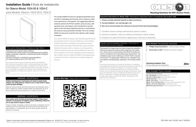
Read guide from beginning to end before beginning installation.
Read all warnings and autions before beginning unit installa-
tion. Che k with your lo al building ode offi ial to identify and
onfirm omplian e with lo al building ode requirements. This
installation guide overs installing your Model 1021 in a typi al
environment. The appropriate method for your installation may
vary based on building design, appli ation, and industry pra ti -
es.
Lea la guía de prin ipio a fin antes de omenzar la instala ión.
Lea todas las adverten ias y pre au iones antes de omenzar la
instala ión de la unidad. Verifique on un ofi ial de ódigo
edili io de su lo alidad para identifi ar y onfirmar el umpli-
miento on los requisitos lo ales del ódigo de edifi a ión. Esta
guía de instala ión ubre la instala ión del Modelo 1021 en un
entorno ade uado. El método apropiado para la instala ión
puede variar según el diseño del edifi io, la apli a ión y las
prá ti as de la industria.
Tools Needed / Herramientas necesarias
Phillips Head S rewdriver / Destornillador Phillips
Torx T20 S rewdriver / Destornillador Torx T20
S rew Gun or Drill / Pistola de tornillo o taladro
Adjustable Wren h / Llave Ajustable
Estimated Installation Time:
Tiempo Estimado de Instalación: 20m
Parts Included / Partes Incluidas
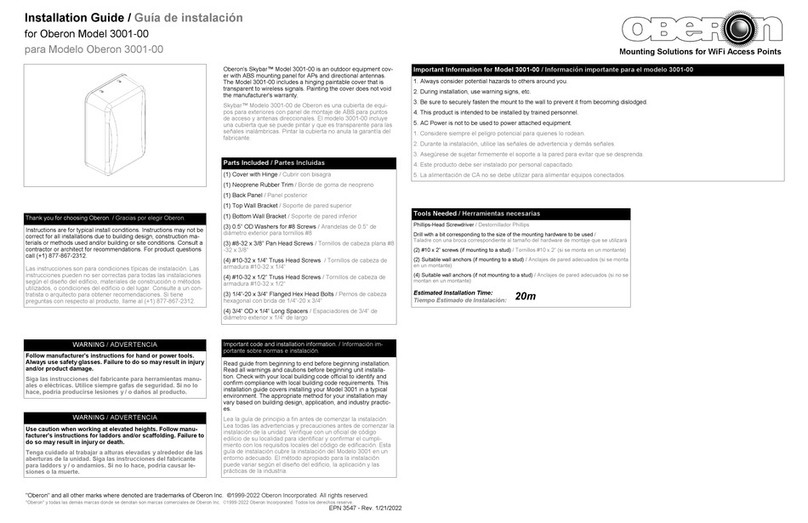
(1) En losure / Re into
(1) T-Bar Bra ket / Soporte de barra en T
(1) Universal Mounting Panel / Panel de montaje universal
(4) Wall Mount Bra kets / Soportes de montaje en pared
(4) M4 x 8 mm Flat Head S rews / Tornillos de abeza plana M4 x 8 mm
(4) M4 x 8 mm Pan Head S rews / Tornillos de abeza plana M4 x 8 mm
(8) M4 x 20 mm Captive Phillips Lid S rews /
Tornillos de tapa Phillips autivos M4 x 20 mm
(8) M4 x 20 mm Captive Torx Lid S rews /
Tornillos de tapa Torx autivos M4 x 20 mm
(4) #6 x 5/16” Pan Head Thread-Forming S rews for Plasti /
Tornillos #6 x 5/16" on abeza plana y ros a para plásti o
(4) #6 x 5/16” Flat Head Thread-Forming S rews for Plasti /
Tornillos #6 x 5/16" de abeza plana para ros ar para plásti o
(4) Cushioning Washers / Arandelas de amortigua ión
(1) Antenna Mounting Bra ket (For -ANTPLATE SKUs Only) /
Soporte de montaje de antena (solo para SKU -ANTPLATE)
(8) #6 x 3/8” Pan Head Thread-Forming S rews for Plasti (For
-ANTPLATE SKUs Only) / Tornillos #6 x 3/8" de abeza plana on
forma de ros a para plásti o (solo para SKU -ANTPLATE)
(4) #8 x 5/8” Pan Head S rews (For -ANTPLATE SKUs Only) /
Tornillos de abeza plana #8 x 5/8” (solo para SKU -ANTPLATE)
(4) #6 x 1/2” Pan Head S rews (For -ANTPLATE SKUs Only) /
Tornillos de abeza plana #6 x 1/2" (solo para SKU -ANTPLATE)
1) When installed in en losure, operating temperature range of the A ess Point should be de-rated (lowered) by the amount shown in the spe ifi ation
sheet.
2) The operating temperature de-rating does not in lude solar loading on the en losure. Oberon’s NEMA 4 produ ts are white or light grey to redu e heat-
ing aused by solar loading, however, en losures mounted in dire t sun my get very warm. Painting the en losures a dark olor will in rease solar heating.
Mount en losure out of dire t sun when possible, to redu e solar loading.
3) Cable ingress/egress openings in en losures must be properly sealed to preserve NEMA 4 rating. If able openings are not sealed water-tight, the en lo-
sure is no longer a NEMA 4 en losure.
1) Cuando se instala en un gabinete, el rango de temperatura de fun ionamiento del punto de a eso debe redu irse (redu irse) en la antidad que se
muestra en la hoja de espe ifi a iones.
2) La disminu ión de la temperatura de fun ionamiento no in luye la arga solar en el gabinete. Los produ tos NEMA 4 de Oberon son de olor blan o o
gris laro para redu ir el alentamiento ausado por la arga solar, sin embargo, los gabinetes montados al sol dire to pueden alentarse mu ho. Pintar
los re intos de un olor os uro aumentará el alentamiento solar. Monte la ar asa fuera del sol dire to uando sea posible, para redu ir la arga solar.
3) Las aberturas de entrada / salida de able en re intos deben sellarse ade uadamente para preservar la lasifi a ión NEMA 4. Si las aberturas de los
ables no están selladas a prueba de agua, el gabinete ya no es un gabinete NEMA 4.
Im ortant Note / Nota Im ortante
Installation Guide / Guía de instalación
for Oberon Model 1021-00 & 1021-00-ANTPLATE
para Modelo Oberon 1021-00 & 1021-00-ANTPLATE
Mounting Solutions for WiFi Access Points
"Oberon" and all other marks where denoted are trademarks of Oberon In . ©1999-2020 Oberon In orporated. All rights reserved.
"Oberon" y todas las demás mar as donde se denotan son mar as omer iales de Oberon In . ©1999-2020 Oberon In orporated. Todos los dere hos reserve.
EPN 3200 & 3364 - 6/15/2020
Choose an appropriate lo ation for data and power ingress. Drill an appro-
priately sized hole into the en losure to fit the sele ted onduit size. Fasten
the onduit to the drilled hole.
(For installations using wall mount brackets ONLY) Fasten the wall
mount bra kets to the ba k of the en losure using the provided M4 x 8 mm
flat head s rews.
Elija una ubi a ión ade uada para el ingreso de datos y energía. Taladre un
orifi io del tamaño apropiado en el gabinete para que se ajuste al tamaño
del ondu to sele ionado. Fije el ondu to al orifi io perforado.
(SOLO ara instalaciones que utilizan so ortes de montaje en ared)
Sujete los soportes de montaje en pared a la parte posterior del gabinete
utilizando los tornillos de abeza plana M4 x 8 mm provistos.
1
(For -ANTPLATE SKUs Only) Install the antenna mounting bra ket and
a ess point mounting bra ket, or in luded T-Bar Bra ket, to the internal
panel with the provided #6 x 3/8” s rews.
(Solo ara SKU -ANTPLATE) Instale el soporte de montaje de la antena
y el soporte de montaje del punto de a eso, o el soporte in luido de la
barra en T, en el panel interno on los tornillos #6 x 3/8” provistos.
2d
3a
To mount the Cis o AIR-BRACKET-1 or -2, align the bra ket’s four (4)
“A” marked holes with the four (4) embosses on the en losure base la-
beled “A” on the mounting legend.
If installing the AIR-BRACKET-1, use the four (4) provided #6 x 5/16” flat
head s rews to fasten the bra ket to the en losure base.
If installing the AIR-BRACKET-2, use the four (4) provided #6 x 5/16”
pan head s rews to fasten the bra ket to the en losure base.
Para montar Cis o AIR-BRACKET-1 o -2, alinee los uatro (4) agujeros
mar ados on "A" del soporte on los uatro (4) relieves en la base del
gabinete etiquetados omo "A" en la leyenda de montaje.
Si instala el AIR-BRACKET-1, use los uatro (4) tornillos #6 x 5/16” de
abeza plana provistos para fijar el soporte a la base del gabinete.
Si instala el AIR-BRACKET-2, use los uatro (4) tornillos #6 x 5/16” de
abeza plana provistos para fijar el soporte a la base del gabinete.
To mount the T-Bar bra ket, align the bra ket’s holes with the two (2)
embosses labeled “B” on the mounting legend. Fasten the T-Bar Bra ket
dire tly to the en losure using two (2) of the provided #6 x 5/16" pan
head s rews.
Para montar el soporte de la barra en T, alinee los agujeros del soporte
on los dos (2) relieves etiquetados "B" en la leyenda de montaje. Sujete
el soporte de la barra en T dire tamente al gabinete utilizando dos (2) de
los tornillos de abeza plana #6 x 5/16" provistos.
Use (4) #10 x 2” s rews (not in luded) and suitable an hor hardware (not
in luded) to fasten to the wall or surfa e.
(For installations that require cushioning washers) Insert a ushioning
washer between ea h of the wall mount bra kets and the wall or surfa e.
Tighten the s rews uniformly around the box so that it does not flex.
Use (4) tornillos #10 x 2” (no in luidos) y herrajes de an laje ade uados (no
in luidos) para fijar a la pared o superfi ie.
(Para instalaciones que requieren arandelas de amortiguación) Inserte
una arandela de amortigua ión entre ada uno de los soportes de montaje
en pared y la pared o superfi ie.
Apriete los tornillos de manera uniforme alrededor de la aja para que no se
doble.
2a
Cisco
2b
Aruba
Other
2c
Other
The universal mounting bra ket is required to mount other types of APs.
It an also be used as an alternate method of mounting the T-Bar (shown
above) or the Cis o Air-Bra ket.
(For -ANTPLATE SKUs Only) The Universal Mounting Bra ket is re-
quired to mount both the antenna mounting bra ket and the AP mounting
hardware.
To install the universal mounting bra ket, fasten it to the en losure using
the four (4) provided M4 x 8 mm Pan Head S rews. Use the provided #6
x 5/16” s rews to mount the T-Bar, the Cis o Air-Bra ket, or to dire tly
mount other APs to the mounting bra ket.
Se requiere el soporte de montaje universal para montar otros tipos de
AP. También se puede usar omo un æmétodo alternativo para montar la
barra en T (que se muestra arriba) o el soporte de aire de Cis o.
(Solo ara SKU -ANTPLATE) Se requiere el soporte de montaje univer-
sal para montar tanto el soporte de antena omo el hardware de montaje
AP.
Para instalar el soporte de montaje universal, fíjelo al gabinete utilizando
los uatro (4) tornillos de abeza plana M4 x 8 mm provistos. Use los
tornillos #6 x 5/16" provistos para montar la barra en T, el soporte de aire
de Cis o o para montar dire tamente otros AP en el soporte de montaje.
Aruba
Other
Cisco
***NOTE: The AP maximum o erating tem erature should be
de-rated by 11°C inside the enclosure when solar loading is
not resent. The Model 1021 is white to reduce solar loading,
while ainting the enclosure a darker color will increase solar
loading. Avoid mounting the 1021 where it is ex osed to direct
sunlight.
***NOTA: La tem eratura máxima de funcionamiento AP debe
reducirse en 11°C dentro del gabinete cuando no hay carga
solar. El modelo 1021 es blanco ara reducir la carga solar,
mientras que intar el gabinete con un color más oscuro au-
mentará la carga solar. Evite montar el 1021 donde esté ex-
uesto a la luz solar directa.
***NOTE: For ste s 2a, 2b, 2c, and 2d, reference the mounting
legend on age 1.
***NOTA: Para los asos 2a, 2b, 2c, y 2d, consulte la leyenda
de montaje en la ágina 1.
***NOTE: If the wall or surface to which the enclosure is at-
tached is not com letely smooth and flat, it is recommended
that the cushioning washers be laced between the mounting
tabs and the wall or surface. The cushioning washers will
reduce flexing by the enclosure when tightened against an
uneven surface, which can cause the seal between the lid
and box to o en.
***NOTA: Si la ared o su erficie a la que se adjunta el gabi-
nete no es com letamente lisa y lana, se recomienda colo-
car las arandelas de amortiguación entre las estañas de
montaje y la ared o su erficie. Las arandelas de amorti-
guación reducirán la flexión del gabinete cuando se a rietan
contra una su erficie irregular, lo que uede hacer que se
abra el sello entre la ta a y la caja.
Aruba
Cisco
Installation Guide / Guía de instalación
for Oberon Model 1021-00 & 1021-00-ANTPLATE
para Modelo Oberon 1021-00 & 1021-00-ANTPLATE
Mounting Solutions for WiFi Access Points
"Oberon" and all other marks where denoted are trademarks of Oberon In . ©1999-2020 Oberon In orporated. All rights reserved.
"Oberon" y todas las demás mar as donde se denotan son mar as omer iales de Oberon In . ©1999-2020 Oberon In orporated. Todos los dere hos reserve.
EPN 3200 & 3364 - 6/15/2020
Atta h the antenna with the provided #8 x 5/8” s rews for Cis o Antennas,
or #6 x 1/2” S rews for Aruba Networks and other antennas.
Cone te la antena on los tornillos suministrados #8 x 5/8" para Antenas de
Cis o, o on los Tornillos #6 x 1/2" para Aruba Networks y otras antenas.
4
Atta h any ables to the A ess Point. Then fasten to the installed AP
mounting bra ket or T-Bar Bra ket. Some A ess Points may need to be
dire tly mounted to the internal panel by drilling pilot holes.
(For -ANTPLATE SKUs ONLY) Conne t the antenna to the A ess
Point.
Cone te los ables al punto de a eso. Luego, fíjelo al soporte de mon-
taje AP instalado o al soporte de la barra en T. Es posible que algunos
puntos de a eso deban montarse dire tamente en el panel interno
taladrando agujeros piloto.
(SOLO PARA SKU-ANTPLATE) Cone te la antena al punto de a eso.
5
(For -ANTPLATE SKUs ONLY) Arti ulate the antenna for proper align-
ment and tighten the hex s rews.
After the ables are atta hed, pla e the lid on the base then se ure it
with the eight (8) M4 x 20 mm pan head ma hine s rews or tamper re-
sistant Torx s rews provided with the en losure. The s rews should be
tightened to 8 in-lbs to properly seal the en losure. Do not over tighten.
Make sure the gasket is properly seated prior to tightening.
The installation is now omplete.
(SOLO PARA SKU-ANTPLATE) Arti ule la antena para una alinea ión
ade uada y apriete los tornillos hexagonales.
Después de one tar los ables, oloque la tapa en la base y luego
asegúrela on los o ho (8) tornillos de abeza plana M4 x 20 mm o los
tornillos Torx resistentes a la manipula ión provistos on el gabinete.
Los tornillos deben apretarse a 8 in-lb para sellar ade uadamente el
gabinete. No apriete demasiado. Asegúrese de que la junta esté asen-
tada orre tamente antes de apretarla.
La instala ión está ompleta.
6
3b
The en losure may also be dire tly mounted to a surfa e without the mount-
ing feet. Drill 1/4” holes through the box in four (4) orners. Use four (4) #10
x 2” s rews (not in luded) and suitable an hor hardware (not in luded) to
fasten to the wall or eiling.
(For installations that require cushioning washers) Insert a ushioning
washer between the box and surfa e in ea h orner.
Tighten s rews uniformly around the box so it does not flex. Properly seal
any openings to maintain NEMA 4 rating.
El re into también se puede montar dire tamente en una superfi ie sin los
pies de montaje. Taladre agujeros de 1/4 ”a través de la aja en uatro (4)
esquinas. Use uatro (4) tornillos #10 x 2” (no in luidos) y herrajes de an la-
je ade uados (no in luidos) para fijarlos a la pared o al te ho.
(Para instalaciones que requieren arandelas de amortiguación) Inserte
una arandela de amortigua ión entre la aja y la superfi ie en ada esquina.
Apriete los tornillos de manera uniforme alrededor de la aja para que no se
doble. Selle ade uadamente las aberturas para mantener la lasifi a ión
NEMA 4.

This manual suits for next models

1

Other OBERON Enclosure manuals

OBERON 1027-00 User manual

OBERON

OBERON 1027-00 User manual

OBERON 1074-SC-04-DOME User manual

OBERON

OBERON 1074-SC-04-DOME User manual

OBERON 1028-08-ANT5-B User manual

OBERON

OBERON 1028-08-ANT5-B User manual

OBERON 1024-00 User manual

OBERON

OBERON 1024-00 User manual

OBERON 1026 Series User manual

OBERON

OBERON 1026 Series User manual

OBERON 1030-00 User manual

OBERON

OBERON 1030-00 User manual

OBERON 1030-00 User manual

OBERON

OBERON 1030-00 User manual

OBERON 1052-AN-ANT16 Manual

OBERON

OBERON 1052-AN-ANT16 Manual

OBERON 1020-RAB-PMK User manual

OBERON

OBERON 1020-RAB-PMK User manual

OBERON 1024-00 User manual

OBERON

OBERON 1024-00 User manual

OBERON 3001-00 User manual

OBERON

OBERON 3001-00 User manual

OBERON 1020-00 User manual

OBERON

OBERON 1020-00 User manual

OBERON 1017 User manual

OBERON

OBERON 1017 User manual

OBERON 1015-00 Service manual

OBERON

OBERON 1015-00 Service manual

Popular Enclosure manuals by other brands

StarTech.com S354UFER user guide

StarTech.com

StarTech.com S354UFER user guide

Quantum DLT Rack1 quick start guide

Quantum

Quantum DLT Rack1 quick start guide

HP D2000 Specifications

HP

HP D2000 Specifications

D-Link DSM-G600 - MediaLounge Wireless G Network Storage Enclosure NAS... manual

D-Link

D-Link DSM-G600 - MediaLounge Wireless G Network Storage Enclosure NAS... manual

Akasa Integral LAN user manual

Akasa

Akasa Integral LAN user manual

Hubbell AccelTex ATS-NL-IC-ENC-15153 installation guide

Hubbell

Hubbell AccelTex ATS-NL-IC-ENC-15153 installation guide

Riotoro CR500 manual

Riotoro

Riotoro CR500 manual

Phanteks Enthoo Series user manual

Phanteks

Phanteks Enthoo Series user manual

ZALMAN Z3 Series manual

ZALMAN

ZALMAN Z3 Series manual

Diablotek CPA-808 Specifications

Diablotek

Diablotek CPA-808 Specifications

StarTech.com S251BU31REMD quick start guide

StarTech.com

StarTech.com S251BU31REMD quick start guide

Kicker TCVT12 owner's manual

Kicker

Kicker TCVT12 owner's manual

Ultra Products Mid-Tower ATX Cases Wizard Specification sheet

Ultra Products

Ultra Products Mid-Tower ATX Cases Wizard Specification sheet

Supermicro SC847E1C Series user manual

Supermicro

Supermicro SC847E1C Series user manual

Macpower & Tytech Hydra S2 user manual

Macpower & Tytech

Macpower & Tytech Hydra S2 user manual

Fractal Terra user guide

Fractal

Fractal Terra user guide

HP 418800-B21 - StorageWorks Modular Smart Array 70 Storage... Maintenance and service guide

HP

HP 418800-B21 - StorageWorks Modular Smart Array 70 Storage... Maintenance and service guide

Thermaltake Shark user manual

Thermaltake

Thermaltake Shark user manual

manuals.online logo
manuals.online logoBrands
  • About & Mission
  • Contact us
  • Privacy Policy
  • Terms and Conditions

Copyright 2025 Manuals.Online. All Rights Reserved.