manuals.online logo
Brands
  1. Home
  2. •
  3. Brands
  4. •
  5. OBERON
  6. •
  7. Enclosure
  8. •
  9. OBERON 3001-00 User manual

OBERON 3001-00 User manual

Installation Guide / Guía de instalación
for Oberon Model 3001-00
para Modelo Oberon 3001-00
Mounting Solutions for WiFi Access Points
"Oberon" and all other marks where denoted are trademarks of Oberon Inc. ©1999-2022 Oberon Incorporated. All rights reser ed.
"Oberon" y todas las demás marcas donde se denotan son marcas comerciales de Oberon Inc. ©1999-2022 Oberon Incorporated. Todos los derechos reser e.
EPN 3547 - Re . 1/21/2022
Oberon's Skybar™ Model 3001-00 is an outdoor equipment co -
er with ABS mounting panel for APs and directional antennas.
The Model 3001-00 includes a hinging paintable co er that is
transparent to wireless signals. Painting the co er does not oid
the manufacturer's warranty.
Skybar™ Modelo 3001-00 de Oberon es una cubierta de equi-
pos para exteriores con panel de montaje de ABS para puntos
de acceso y antenas direccionales. El modelo 3001-00 incluye
una cubierta que se puede pintar y que es transparente para las
señales inalámbricas. Pintar la cubierta no anula la garantía del
fabricante.
Instructions are for typical install conditions. Instructions may not be
correct for all installations due to building design, construction ma-
terials or methods used and/or building or site conditions. Consult a
contractor or architect for recommendations. For product questions
call (+1) 877-867-2312.
Las instrucciones son para condiciones típicas de instalación. Las
instrucciones pueden no ser correctas para todas las instalaciones
según el diseño del edificio, materiales de construcción o métodos
utilizados, o condiciones del edificio o del lugar. Consulte a un con-
tratista o arquitecto para obtener recomendaciones. Si tiene
preguntas con respecto al producto, llame al (+1) 877-867-2312.
Thank you for choosing Oberon. / Gracias por elegir Oberon.
WARNING / ADVERTENCIA
Follow manufacturer's instructions for hand or ower tools.
Always use safety glasses. Failure to do so may result in injury
and/or roduct damage.
Siga las instrucciones del fabricante ara herramientas manu-
ales o eléctricas. Utilice siem re gafas de seguridad. Si no lo
hace, odría roducirse lesiones y / o daños al roducto.
WARNING / ADVERTENCIA
Use caution when working at elevated heights. Follow manu-
facturer's instructions for laddors and/or scaffolding. Failure to
do so may result in injury or death.
Tenga cuidado al trabajar a alturas elevadas y alrededor de las
aberturas de la unidad. Siga las instrucciones del fabricante
ara laddors y / o andamios. Si no lo hace, odría causar le-
siones o la muerte.
Im ortant Information for Model 3001-00 / Información im ortante ara el modelo 3001-00
1. Always consider potential hazards to others around you.
2. During installation, use warning signs, etc.
3. Be sure to securely fasten the mount to the wall to pre ent it from becoming dislodged.
4. This product is intended to be installed by trained personnel.
5. AC Power is not to be used to power attached equipment.
1. Considere siempre el peligro potencial para quienes lo rodean.
2. Durante la instalación, utilice las señales de ad ertencia y demás señales.
3. Asegúrese de sujetar firmemente el soporte a la pared para e itar que se desprenda.
4. Este producto debe ser instalado por personal capacitado.
5. La alimentación de CA no se debe utilizar para alimentar equipos conectados.
Important code and installation information. / Información im-
portante sobre normas e instalación.
Read guide from beginning to end before beginning installation.
Read all warnings and cautions before beginning unit installa-
tion. Check with your local building code official to identify and
confirm compliance with local building code requirements. This
installation guide co ers installing your Model 3001 in a typical
en ironment. The appropriate method for your installation may
ary based on building design, application, and industry practic-
es.
Lea la guía de principio a fin antes de comenzar la instalación.
Lea todas las ad ertencias y precauciones antes de comenzar la
instalación de la unidad. Verifique con un oficial de código
edilicio de su localidad para identificar y confirmar el cumpli-
miento con los requisitos locales del código de edificación. Esta
guía de instalación cubre la instalación del Modelo 3001 en un
entorno adecuado. El método apropiado para la instalación
puede ariar según el diseño del edificio, la aplicación y las
prácticas de la industria.
Tools Needed / Herramientas necesarias
Phillips-Head Screwdri er / Destornillador Phillips
Drill with a bit corresponding to the size of the mounting hardware to be used /
Taladre con una broca correspondiente al tamaño del hardware de montaje que se utilizará
(2) #10 x 2” screws (if mounting to a stud) / Tornillos #10 x 2” (si se monta en un montante)
(2) Suitable wall anchors (if mounting to a stud) / Anclajes de pared adecuados (si se monta
en un montante)
(4) Suitable wall anchors (if not mounting to a stud) / Anclajes de pared adecuados (si no se
montan en un montante)
Estimated Installation Time:
Tiempo Estimado de Instalación:
20m
Parts Included / Partes Incluidas
(1) Co er with Hinge / Cubrir con bisagra
(1) Neoprene Rubber Trim / Borde de goma de neopreno
(1) Back Panel / Panel posterior
(1) Top Wall Bracket / Soporte de pared superior
(1) Bottom Wall Bracket / Soporte de pared inferior
(3) 0.5” OD Washers for #8 Screws / Arandelas de 0.5” de
diámetro exterior para tornillos #8
(3) #8-32 x 3/8” Pan Head Screws / Tornillos de cabeza plana #8
-32 x 3/8”
(4) #10-32 x 1/4” Truss Head Screws / Tornillos de cabeza de
armadura #10-32 x 1/4”
(4) #10-32 x 1/2” Truss Head Screws / Tornillos de cabeza de
armadura #10-32 x 1/2”
(3) 1/4”-20 x 3/4” Flanged Hex Head Bolts / Pernos de cabeza
hexagonal con brida de 1/4”-20 x 3/4”
(4) 3/4” OD x 1/4” Long Spacers / Espaciadores de 3/4” de
diámetro exterior x 1/4” de largo
Installation Guide / Guía de instalación
for Oberon Model 3001-00
para Modelo Oberon 3001-00
Mounting Solutions for WiFi Access Points
"Oberon" and all other marks where denoted are trademarks of Oberon Inc. ©1999-2022 Oberon Incorporated. All rights reser ed.
"Oberon" y todas las demás marcas donde se denotan son marcas comerciales de Oberon Inc. ©1999-2022 Oberon Incorporated. Todos los derechos reser e.
EPN 3547 - Re . 1/21/2022
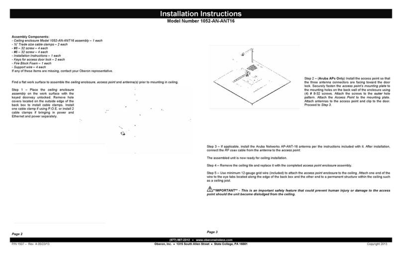
Using the keyhole slots of the Top and Bottom Wall Brackets, mark the
fastening points on the mounting surface. The 3001-00 can be con eniently
installed directly o er a telecommunications outlet. It is recommended that
the enclosure be fastened to a stud if possible. If mounting the 3001-00 to a
stud, use a #10 x 2” or larger screw (not included) for each of the two (2)
keyhole slots that are aligned ertically with the stud and suitable wall an-
chors for the other two (2) keyhole slots. If there is no stud at the mounting
location, use four (4) wall anchors suitable for the wall’s construction, such
as threaded drywall anchors, threaded drywall toggles, slee e type hollow
wall anchors (a.k.a. molly bolts) or toggle bolts. There should be enough
clearance between the bottom of the screw head and the wall for both key-
hole slots on both wall brackets to engage the screws. Due to the weight of
the AP, AP antenna, and the 3001-00, plastic wall anchors are not recom-
mended for fastening the enclosure to the wall.
Utilizando las ranuras de ojo de cerradura de los soportes de pared superior
e inferior, marque los puntos de fijación en la superficie de montaje. El 3001
-00 se puede instalar cómodamente directamente sobre una toma de tele-
comunicaciones. Se recomienda que la caja se sujete a un montante si es
posible. Si monta el 3001-00 en un montante, use un tornillo #10 x 2” o más
grande (no incluido) para cada una de las dos (2) ranuras de bocalla e que
están alineadas erticalmente con el montante y anclajes de pared adecua-
dos para los otros dos (2) ranuras de ojo de cerradura. Si no hay un mon-
tante en la ubicación de montaje, use cuatro (4) anclajes de pared adecua-
dos para la construcción de la pared, como anclajes roscados para paneles
de yeso, pernos roscados para paneles de yeso, anclajes de pared huecos
tipo manguito (también conocidos como pernos Molly) o pernos de palanca.
Debe haber suficiente espacio libre entre la parte inferior de la cabeza del
tornillo y la pared para que ambas ranuras en forma de ojo de cerradura en
ambos soportes de pared encajen con los tornillos. Debido al peso del AP,
la antena AP y el 3001-00, no se recomiendan anclajes de pared de plástico
para sujetar el gabinete a la pared.
1
Loosely fasten the two (2) 1/4”-20 x 3/4” Flange Hex Head Bolts to the
Top Wall Bracket.
Sujete sin apretar los dos (2) pernos de cabeza hexagonal con brida de
1/4”-20 x 3/4” al soporte de pared superior.
2
Attach any equipment to the Back Panel, then place the assembly onto
the wall. Finish tightening the wall hardware, and connect any equip-
ment power and data cables.
Fije cualquier equipo al panel posterior y luego coloque el ensamblaje
en la pared. Termine de apretar los accesorios de la pared y conecte
los cables de alimentación y de datos del equipo.
5
Close the co er and tighten the 1/4”-20 x 3/4” Flanged Hex Head Bolts.
The installation is now complete.
Cierre la cubierta y apriete los pernos de cabeza hexagonal con brida de
1/4”-20 x 3/4”.
La instalación está completa.
6
Insert the threaded standoffs of the hinge into the slots of the Bottom
Bracket. Fasten the hinge to the Bottom Bracket using the three (3)
included #8-32 x 3/8” Screws and 0.5” OD Washers, as shown abo e.
NOTE: Before fastening the hinge to the bracket, the Neoprene Trim
may be applied to the edge of the co er.
Inserte los separadores roscados de la bisagra en las ranuras del so-
porte inferior. Fije la bisagra al soporte inferior usando los tres (3) torni-
llos incluidos #8-32 x 3/8” y arandelas de 0.5” de diámetro exterior,
como se muestra arriba.
NOTA: Antes de fijar la bisagra al soporte, se puede aplicar el borde de
neopreno en el borde de la cubierta.
4
OPTIONAL: Four (4) Spacers are included to offset the Back Panel from
the wall, which may be necessary if the wall’s surface is une en. It may
also be necessary if using fastening hardware that sticks through the
opposite side of the Back Panel. To use the spacers, remo e the #10-32
x 1/4” screws that are securing the Back Panel to the Top and Bottom
Brackets. Next, separate the Back Panel from the Top and Bottom Brack-
ets. Then, place one (1) of the four (4) spacers around each of the Brack-
ets’ two (2) threaded inserts. Finally, align the Back Panel’s with the Top
and Bottom Brackets and secure the Back Panel with the four (4) includ-
ed #10-32 x 1/2” screws.
OPCIONAL: Se incluyen cuatro (4) espaciadores para desplazar el panel
posterior de la pared, lo que puede ser necesario si la superficie de la
pared es irregular. También puede ser necesario si usa herrajes de suje-
ción que sobresalen del lado opuesto del panel posterior. Para usar los
espaciadores, quite los tornillos #10-32 x 1/4” que aseguran el panel
posterior a los soportes superior e inferior. A continuación, separe el
panel posterior de los soportes superior e inferior. Luego, coloque uno
(1) de los cuatro (4) espaciadores alrededor de cada uno de los dos (2)
insertos roscados de los soportes. Finalmente, alinee el panel posterior
con los soportes superior e inferior y asegure el panel posterior con los
cuatro (4) tornillos incluidos #10-32 x 1/2”.
3

Other OBERON Enclosure manuals

OBERON 1074-SC-04-DOME User manual

OBERON

OBERON 1074-SC-04-DOME User manual

OBERON 1015-00 Service manual

OBERON

OBERON 1015-00 Service manual

OBERON 1020-00 User manual

OBERON

OBERON 1020-00 User manual

OBERON 1020-RAB-PMK User manual

OBERON

OBERON 1020-RAB-PMK User manual

OBERON 1026 Series User manual

OBERON

OBERON 1026 Series User manual

OBERON 1027-00 User manual

OBERON

OBERON 1027-00 User manual

OBERON 1030-00 User manual

OBERON

OBERON 1030-00 User manual

OBERON 1024-00 User manual

OBERON

OBERON 1024-00 User manual

OBERON 1021-00 User manual

OBERON

OBERON 1021-00 User manual

OBERON 1028-08-ANT5-B User manual

OBERON

OBERON 1028-08-ANT5-B User manual

OBERON 1052-AN-ANT16 Manual

OBERON

OBERON 1052-AN-ANT16 Manual

OBERON 1030-00 User manual

OBERON

OBERON 1030-00 User manual

OBERON 1017 User manual

OBERON

OBERON 1017 User manual

OBERON 1024-00 User manual

OBERON

OBERON 1024-00 User manual

Popular Enclosure manuals by other brands

SFF time P-ATX V2.1 manual

SFF time

SFF time P-ATX V2.1 manual

L-Acoustics WST K2 Rigging manual

L-Acoustics

L-Acoustics WST K2 Rigging manual

Hama 2.5" Hard disk Enclosure installation guide

Hama

Hama 2.5" Hard disk Enclosure installation guide

Icy Box IB-183M2 Quick installation guide

Icy Box

Icy Box IB-183M2 Quick installation guide

Macpower & Tytech Hydra 800+ user manual

Macpower & Tytech

Macpower & Tytech Hydra 800+ user manual

UTC Fire and Security interlogix 60-928 installation instructions

UTC Fire and Security

UTC Fire and Security interlogix 60-928 installation instructions

Siemon Lightverse Plus instructions

Siemon

Siemon Lightverse Plus instructions

Hamlet HXD3SAUU user manual

Hamlet

Hamlet HXD3SAUU user manual

Gembird EE3-U3S-3 user manual

Gembird

Gembird EE3-U3S-3 user manual

Springfree S113 Assembly instructions

Springfree

Springfree S113 Assembly instructions

Belkin P35772ec instructions

Belkin

Belkin P35772ec instructions

Raidon ST7610-4S-S2P user manual

Raidon

Raidon ST7610-4S-S2P user manual

Stillwater Designs Kicker KS Series owner's manual

Stillwater Designs

Stillwater Designs Kicker KS Series owner's manual

molex Box 601 installation instructions

molex

molex Box 601 installation instructions

SilverStone TS10 installation guide

SilverStone

SilverStone TS10 installation guide

2B Technologies 106 installation manual

2B Technologies

2B Technologies 106 installation manual

Antec Quiet Computing Mini Skeleton-90 user manual

Antec

Antec Quiet Computing Mini Skeleton-90 user manual

Airlink101 AEN-U55W user manual

Airlink101

Airlink101 AEN-U55W user manual

manuals.online logo
manuals.online logoBrands
  • About & Mission
  • Contact us
  • Privacy Policy
  • Terms and Conditions

Copyright 2025 Manuals.Online. All Rights Reserved.