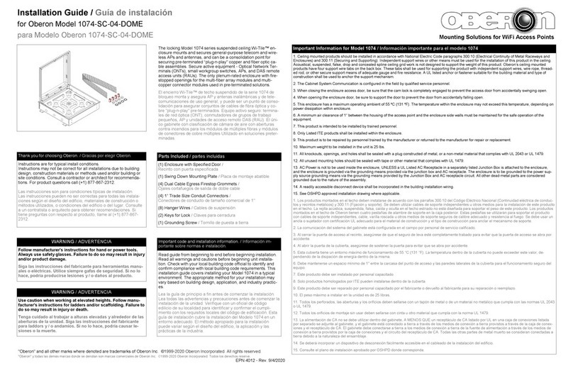
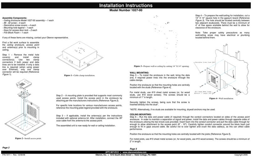
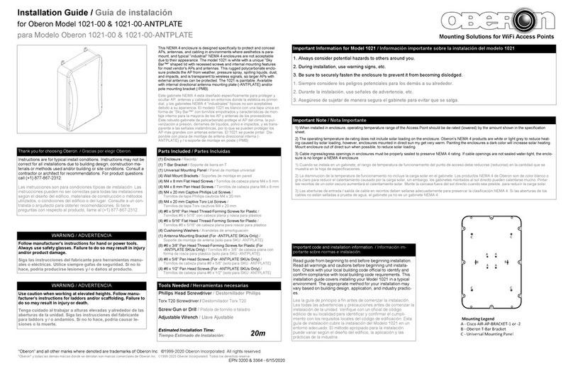
Assembly Components:
- Wall / Ceiling Enclosure, Model 1030-00 assembly – 1 each
- #6-32 crews – 4 each
- #8-32 crews – 4 each
- #10-32 crews – 4 each
- #6-32 Hex Nuts – 2 each
- ½” Trade ize Cable Clamp
- Keys for access door lock – 2 each
If any of these items are missing, contact your Oberon representative.
Find a flat ork surface to assemble the all/ceiling enclosure and access point prior to mounting.
Step 1 – Open the enclosure door and mount the access point’s mounting plate per the mounting hole legend (Ref. Figure 1).
Note t at Aruba Networks sells t e mounting plate kits separately. To install Aruba Access Points you will need to
purc ase t e mounting plate kit required for your application. Remove mounting plate from enclosure and use Aruba
Networks AP-105-MNT for AP105 and use Aruba Networks AP-135-MNT for AP135 (ref. Fig. 2).
Step 2 – If mounting the enclosure on a all or hard lid surface, remove the ¼” knockouts located on the four corners of the
back box so that you ill be able to mount to surface using scre s and anchors (not included). Leave these knockouts in
place if you are using the optional flange (Oberon P/N “1030-FLANGE”) for ceiling mount installations.
Step 3 – Decide the best location
from hich to bring in the Ethernet
cable. There are t o (2) ¾” trade
size knockouts located against the
back surface of the enclosure and
six (6) ½” trade size clamps located
on the top and bottom surface of the
enclosure. Remove the knockout
that best fits your application. (Note:
The knockouts located on the top
and bottom alls of the enclosure
can also be used for external
antennas if required). Install the
cable clamp.
If using t e optional flange kit to
mount in a drop ceiling, skip
a ead to “Step 8”.
Step 4 – Place the enclosure
against the surface to hich it ill
be mounted and mark the hole
locations to drill pilot holes.
Step 5 – Set the enclosure to the
side and drill holes for all anchors.
Install the all anchors and mount the enclosure.
Step 6 – Bring in the Ethernet cable and attach to the access point.
Step 7 – Attach the access point to the previously installed access point mounting plate, close and lock the door. Installation is
no complete.
OPTIONAL FLANGE INSTRUCTIONS:
Assemble Components:
- Model 1030-FLANGE – 1 each
- #8-32 Scre s – 8 each
Step 8 – If mounting the enclosure in a drop ceiling, you ill need to purchase the optional flange kit (Oberon P/N 1030-
FLANGE).
Step 9 – To attach the optional flange, place the Model 1030-00 enclosure into the opening as sho n in figure 3. Slide the
1030-00 enclosure into the flange until the scre holes located on the side of the enclosure align ith the oblong holes
located on the edge of the flange. The front surface of the enclosure door should align ith the front surface of the flange ith
the dome protruding its full height.
Figure 1 – Mounting hole legend . Figure 1 – Aru a Networks AP105 Installation
