OBO Bettermann Ion Wallbox Basic Protect User manual

OBO Bettermann Holding GmbH & Co. KG
Only for electricians
Mounting
instructions
Ion Basic charging station
Ion Key charging station
Ion Basic Protect charging station
Ion Key Protect charging station

© 2023 OBO Bettermann Holding GmbH & Co. KG
Ion Basic charging station
Ion Key charging station
Ion Basic Protect charging station
Ion Key Protect charging station
Mounting instructions

3 | EN
Mounting instructions for the Ion charging stations
Table of contents
Table of contents
1 About these instructions . . . . . . . . . . . . . . . . . . . . . 5
1.1 Target group . . . . . . . . . . . . . . . . . . . . . . . . . . . . . . . . . . 5
1.2 Relevance of these instructions . . . . . . . . . . . . . . . . . . . . . . . . . 5
1.3 Types of warning information . . . . . . . . . . . . . . . . . . . . . . . . . . 5
1.4 Basic standards and regulations . . . . . . . . . . . . . . . . . . . . . . . . 6
1.5 Applicable documents . . . . . . . . . . . . . . . . . . . . . . . . . . . . . 6
2 Intended use . . . . . . . . . . . . . . . . . . . . . . . . . . . 6
3 Safety . . . . . . . . . . . . . . . . . . . . . . . . . . . . . . .6
3.1 General safety information . . . . . . . . . . . . . . . . . . . . . . . . . . . 6
3.2 Personal protective equipment . . . . . . . . . . . . . . . . . . . . . . . . . 7
3.3 Safety stickers . . . . . . . . . . . . . . . . . . . . . . . . . . . . . . . . . 7
4 Necessary tools . . . . . . . . . . . . . . . . . . . . . . . . . . 7
5 Product overview . . . . . . . . . . . . . . . . . . . . . . . . . 8
5.1 Accessories . . . . . . . . . . . . . . . . . . . . . . . . . . . . . . . . . . . 9
5.2 Product description . . . . . . . . . . . . . . . . . . . . . . . . . . . . . . . 9
6 Mounting and installation . . . . . . . . . . . . . . . . . . . 14
6.1 Criteria for location selection . . . . . . . . . . . . . . . . . . . . . . . . . . 14
6.2 Preparations for mounting . . . . . . . . . . . . . . . . . . . . . . . . . . . 15
6.3 Mounting the charging station. . . . . . . . . . . . . . . . . . . . . . . . . . 16
6.4 Connecting the charging station . . . . . . . . . . . . . . . . . . . . . . . . 18
6.5 Mounting the data cable . . . . . . . . . . . . . . . . . . . . . . . . . . . .20
6.6 Mounting the pressure compensation element . . . . . . . . . . . . . . . . . 21
6.7 Mounting the cable bracket . . . . . . . . . . . . . . . . . . . . . . . . . . .23
6.8 Adjusting the charging current/DIP switch configuration . . . . . . . . . . . .23
6.9 Mounting the weather protection roof . . . . . . . . . . . . . . . . . . . . . .25
6.10 Modifying the software configuration . . . . . . . . . . . . . . . . . . . . . .26
6.11 Controlling the charging station externally via Modbus RTU . . . . . . . . . .27
6.12 Closing the charging station . . . . . . . . . . . . . . . . . . . . . . . . . .28
7 Checking the function . . . . . . . . . . . . . . . . . . . . . 28
8 Charging an electric vehicle . . . . . . . . . . . . . . . . . . 28
9 Troubleshooting . . . . . . . . . . . . . . . . . . . . . . . . 29
10 Maintaining the product . . . . . . . . . . . . . . . . . . . . 29
10.1 Performing a software update . . . . . . . . . . . . . . . . . . . . . . . . . .30
11 Dismantling the product . . . . . . . . . . . . . . . . . . . . 30
12 Disposing of the product . . . . . . . . . . . . . . . . . . . . 30
13 FAQs ‒ frequently asked questions . . . . . . . . . . . . . . 31
14 Technical data . . . . . . . . . . . . . . . . . . . . . . . . . . 31

4 | EN OBO Bettermann
Table of contents

5 | EN
Mounting instructions for the Ion charging stations
About these instructions
1 About these instructions
1.1 Target group
These instructions are intended for electricians. The charging station
may only be mounted and connected, opened or modified by an electri-
cian.
1.2 Relevance of these instructions
These instructions are based on the standards valid at the time of com-
pilation (October 2022).
Please read the instructions carefully before starting mounting. We will
not accept any warranty claims for damage caused through non-obser-
vance of these instructions.
Any images are intended merely as examples. Mounting results may look
different.
All the documents supplied with the product must be stored in an easily
accessible location, so as to be available when information is required.
The current version of the mounting instructions can also be opened
using the QR code on the charging station.
In these instructions, cables and lines are referred to simply as cables.
1.3 Types of warning information
Type of risk!
Shows a risky situation. If the safety instruction is not observed, fatal
injuries will occur.
Type of risk!
Shows a risky situation. If the safety instruction is not observed, then
serious or fatal injuries may occur.
Type of risk!
Shows a risky situation. If the safety instruction is not observed, then
medium or minor injuries may occur.
Type of risk!
Shows a hazardous situation. If the safety instruction is not observed,
then damage to the product or the surroundings may occur.
Note! Indicates important information or assistance.
DANGER
WARNING
CAUTION
ATTENTION

6 | EN OBO Bettermann
Intended use
1.4 Basic standards and regulations
– IEC 61851-1
– IEC 62196-2
1.5 Applicable documents
– Declaration of conformity
– Instruction manual for the Ion charging stations
2 Intended use
As a sole charging point, the Ion charging station is only intended for
charging electric vehicles in private areas with restricted access, e.g.
private land. The charging station is only suitable for permanent mount-
ing on the wall in interior or protected exterior areas. Charging takes
place according to Mode 3 in accordance with IEC 61851-1 with a type 2
connector for charging single-phase, dual-phase or triple-phase electri-
cal vehicles with 11 kW/16 A (factory setting).
Charging electric vehicles with gassing batteries is not permitted.
The charging station is not designed for any use other than that de-
scribed here. If the charging station is used for another purpose, then
this shall render all liability, warranty and damage claims null and void.
3 Safety
3.1 General safety information
Observe the following general safety information:
–Contact with electrical current can lead to an electric shock. Ensure
de-energisation before working on the device.
– If the device presents defects or damage, then this can cause a fire
or people could be injured by an electric shock. Only mount flawless
devices.
– Keep children and animals away from the system.
– People with heart pacemakers or defibrillators may not work on, or be
located in the vicinity of, charging systems and their equipment, e.g.
for maintenance purposes or for troubleshooting.

7 | EN
Mounting instructions for the Ion charging stations
Necessary tools
3.2 Personal protective equipment
List of personal protective equipment to be used:
Wear safety shoes!
Wear suitable safety shoes during transport and mounting, in order to
avoid contusions or crushing injuries.
3.3 Safety stickers
List of safety stickers attached to the device and their meaning:
Danger of electrical voltage!
Ensure de-energisation before working on the device.
Electrical technician!
Only electrical technicians may mount and connect the device.
Protection class!
The device corresponds to Protection Class 1 according to DIN EN 61140
(VDE 0140-1).
4 Necessary tools
List of required tools:
– Drill
– Screwdriver
– Possibly stripping tool
– Possibly crimping tool

8 | EN OBO Bettermann
Product overview
5 Product overview
The Ion charging station series comprises 4 different models. The charg-
ing station possesses different features, depending on the model.
1 2
6
8
9
11
13
12
14
4
3
5
7
10
15
16
17
18
19
20
Component/charging station Ion Basic
charging station
Ion Key charg-
ing station
Ion Basic Pro-
tect charging
station
Ion Key Protect
charging station
1
Charging station
2
Front panel
3
Charging station status LED
4
Surge protection status LED
5
On/off switch without authorisation
On/off switch with authorisation (key
switch)
6
Charging connector, type 2
7
Wall bracket, charging cable
8
Charging cable, 5 m
9Cable entry for supply cable
10
Ion charging station rating plate with
QR code
11
Charging controller, Mode 3
12 Safety fuse 1 A 250 VAC 5x20
13
Surge protection, power line V10
Compact
14 Installation protection
15
Error current monitoring DC
16
Connection terminals
17 Surge protection, data line MDP 5 V
18
Surge protection, data line MDP 12 V

9 | EN
Mounting instructions for the Ion charging stations
Product overview
Component/charging station Ion Basic
charging station
Ion Key charg-
ing station
Ion Basic Pro-
tect charging
station
Ion Key Protect
charging station
19 Potential-free enabling contact (e.g.
for PV systems, ripple controller)
20 Modbus RTU interface
(e.g. connection to external control-
ler)
5.1 Accessories
Figure Designation Item no.
M25/M32 cable gland for
power supply cable
and M12 cable gland for
data cable
Contained in scope
of supply
Weather protection roof for
Basic/Key charging station
Available separately:
6570105
Weather protection roof for
Basic Protect/Key Protect
charging station
Available separately:
6570107
M20 pressure compensation
element
Supplied with weath-
er protection cover,
otherwise available
separately: 2034680
5.2 Product description
The Ion charging stations are intended for charging electric vehicles in
private areas as a sole charging point. The charging stations possess
the following functions and equipment features:
– Charging according to Mode 3 in accordance with IEC 61851-1
– 5 m charging cable with type 2 charging connector
– Single, dual and triple-phase charging
– Suitable for TN and TT networks
– Integrated temperature monitoring
– DC error current monitoring
– Status information via LED display
– Optionally with key switch for authorisation
– Optionally with full range surge protection
– Including cable bracket
– Prewired, ready for connection
– Potential-free enabling contact, e.g. for PV systems, ripple controller
– Limitation of the charging power to a fixed value, factory setting
11 kW, maximum output 22 kW

10 | EN OBO Bettermann
Product overview
– Modbus RTU protocol via RS-485 interface for bidirectional communi-
cation
5.2.1 Charging power and requirements for the supply line
Current
[A]
Charging power [kW] Min.
cross-section,
feed line
[mm²]
Max. feed
line length
[m]
1-phase 2-phase 3-phase
61.4 2.8 4.2 1.5 50
81.8 3.6 5.5 1.5 50
10 2.3 4.6 6.9 1.5 50
13 3.0 6.0 9.0 1.5 37
16 3.6 7.4 11. 0 2.5 51
20 4.6 9.2 13.8 4.0 65
24 –* 11. 0 16.5 4.0 51
32 –* 14.7 22.0 6.0 45
*In Germany, single-phase charging is permitted up to a maximum of
4.6 kW.
5.2.2 LED status display
LED display Description Meaning
Blue, pulsing Ready for charging, vehicle can be
connected
Blue, continuous Connected with the vehicle, but charg-
ing operation not started or completed
Green, continuous Charging vehicle
Red, pulsing Error, charging operation interrupted
No light Device switched off
Tab. 1: LED status display
11 | EN
Mounting instructions for the Ion charging stations
Product overview
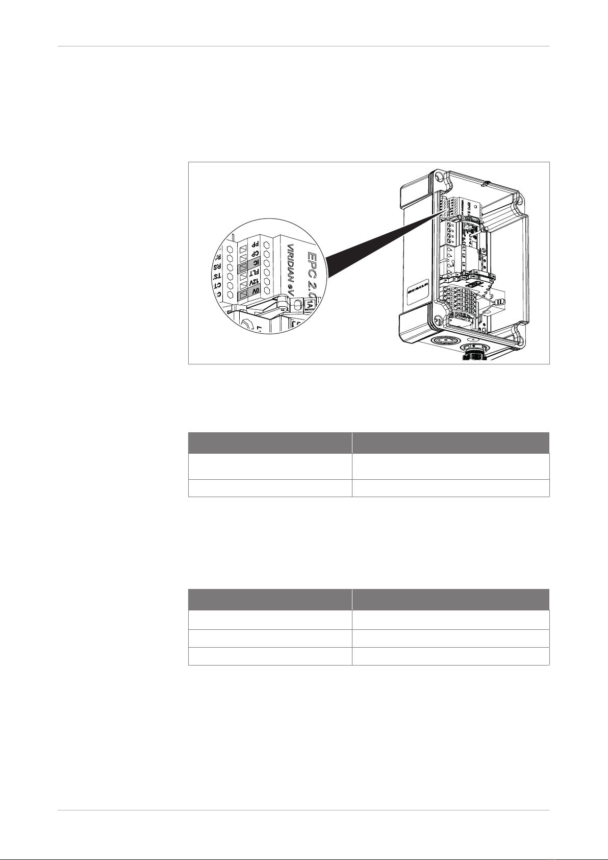
5.2.3 Potential-free enabling contact for Ion Basic charging stations
The Ion Basic charging station scan be activated using an enabling con-
tact through external units such as photovoltaic inverter, ripple control-
ler, timer, external key switch/numeric lock/RFID module. The enabling
contact is a potential-free input on the charging controller between the IC
and 0 V screw terminals.
Fig. 1: IC and 0 V screw terminals on the charging controller
Note This feature is not available when the charging station is switched off.
Enabling contact status Function
IC/0 V closed Not ready for operation, charging not
possible
IC/0 V open Ready for operation, charging possible
Tab. 2: Enabling contact logic
Outside the device, ensure safe electrical separation. If IC/0 V is closed,
a resistance of < 100 ohm must be guaranteed. The cable length/
cross-sections must be selected appropriately.
Feature Value
Screw connections 0.5 Nm tightening torque
Cable cross-section 0.5–2.5 mm²
Stripping 10 mm
Tab. 3: Technical data, IC/0 V cable connection

12 | EN OBO Bettermann
Product overview
Static, PV-optimised charging with enabling contact
=
DC
~
AC
=
~
S1
S2
Fig. 2: Application example of static PV-optimised charging
With static, PV-optimised charging with enabling contact, the IC/0 V
input from the Ion Basic to the inverter (e.g. Fronius, Kostal) is activated.
If sufficient solar power is available, then the inverter allows the charging
operation.
Switch status Function
S1 opened Solar power available (e.g. > 7 A)
S1 closed Solar power low (e.g. < 7 A)
Tab. 4: S1 switch for exchange between enabling contact and inverter
Optionally, the enabling contact can be activated by the customer (user),
e.g. using a surface-mounted changeover switch (S2) or added:
Switch status Function
S2 opened Charging without solar power
S2 closed Charge with solar power available
Tab. 5: S2 switch for activation (charging instantly) by user

13 | EN
Mounting instructions for the Ion charging stations
Product overview
IC
0V
S1
S2
Fig. 3: Example concept for simple PV-optimised charging
5.2.4 Adjusting the charging power with resistors
Alternatively, the charging power can be adjusted between 0V/IC using
resistors, e.g. for DIY applications of external charging power limits, etc.
We recommend limiting the charging power using DIP switches, see
„Tab. 7: DIP switch configuration“ on page 24, for standard applica-
tions. Resistors are not included in the scope of delivery.
Charging power Resistance (tolerance ≤ 1%, 63 mW)
6 A 191 Ω
10 A 249 Ω
16 A 348 Ω
20 A 432 Ω
25 A 536 Ω
32 A 732 Ω
Tab. 6: Charging power dependent on the resistance
5.2.5 Maximum charging power when using the enabling contact
If the enabling contact is used, multiple aspects have weightings of
different strengths on reaching the maximum charging power. With the
Modbus settings, the configuration of the DIP switch cannot be over
written and, with the DIP switch, no higher charging currents can be con-
figured than those that actually arrive at the IC/0 V input.
The following settings are checked:
1. Status of the IC/0 V input
2. DIP switch setting
3. Modbus-RTU activation
However, only the smallest enabled/set charging power is communicated
to the vehicle.
Example:
IC/0 V: 16 A (348 Ω), DIP: 14 A, Modbus 32 A
The car can be charged with a maximum of 14 A.

14 | EN OBO Bettermann
Mounting and installation
6 Mounting and installation
6.1 Criteria for location selection
When selecting the mounting location, observe the following criteria, in
order to guarantee safe operation of the charging station:
– Take into account the risk of flooding, local fire prevention measures,
accident prevention regulations and rescue routes at the location.
– Do not mount the charging station in potentially explosive areas, and
areas with direct sunlight, heat or water jets.
– Ambient temperature –10 °C to 50 °C .
– Mount the charging station at a maximum geographic mounting height
of 2,000 m above sea level.
– Do not mount the charging station in the vicinity of sources of interfer-
ence or heat, such as frequency converters. These can interfere with
the operation of the charging station.
– Mount the charging station on a wall in interior areas or protected
exterior areas. To protect the charging station, mount the separately
available weather protection roof in the protected exterior area. Dur-
ing mounting in the protected exterior area, you should also use the
pressure compensation element (contained in the scope of delivery of
the weather protection roof).
– If strong temperature deviations and heat bridges are to be expected
in interior areas, then a pressure compensation element must also
be used here, in order to avoid the formation of condensation in the
charging unit. The pressure compensation unit must be ordered sep-
arately (item no. 2034680).
– Only mount the charging unit on a flat surface made of concrete, tiles
or other non-combustible materials. When mounting on wood, mount
additional protection made of a non-combustible material, e.g. metal
plate, between the charging station and the wooden substrate. Mount-
ing on lightweight construction walls is not permitted.
– Observe the load capacity of the wall upon which the charging station
is mounted.
– The technical data of the charging station and the network data at the
mounting location must agree.
– Only mount the charging station in a vertical position and observe the
minimum distances to other components or walls and the maximum
distance between the charging station and the electric vehicle.
– In addition, choose the position of the charging station in agreement
with the user. In so doing, observe the position of the charging point
on the car and the normal parking behaviour, in order to guarantee a
sufficient cable length.

15 | EN
Mounting instructions for the Ion charging stations
Mounting and installation
≤ 4,5 m
≥ 900 mm
≥ 200 mm ≥ 200 mm
≥ 200 mm
85 ± 5 mm
55 mm
Fig. 4: Distances to be maintained
6.2 Preparations for mounting
Before mounting the charging station, the following preparatory work
must be performed:
– Installation of an additional circuit breaker with a C trigger character-
istic in the building installation. This must be selected according to the
output of the charging station.
– Installation of an additional type A fault current protection switch
(RDC) in the building installation.
– Preparation of the supply line.
– Preparation of the data cable (Modbus), if necessary, installation of a
terminating resistor (e.g. 150 ohm).
– If no Modbus communication is currently required, then preparation
with a pipe or duct, etc. is recommended for later installation.
– Preparation of the enabling contact (see „5.2.3 Potential-free enabling
contact for Ion Basic charging stations“ on page 11).
Note! Additional lightning protection measures may be required, depending on
the installation conditions, e.g. supply line lengths of over 10 m.
Note! The on-site factors must always be taken into account during installation.
If the installation conditions change, it may also be necessary to adjust
the installation of the charging station.

16 | EN OBO Bettermann
Mounting and installation
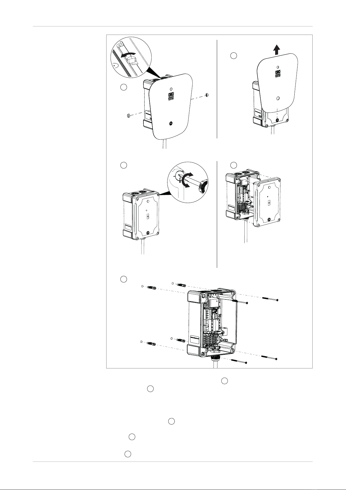
6.3 Mounting the charging station
Fig. 5:
213
163
Ion Wallbox
Drawing on the drill holes
1. Draw on the fastening points using the appropriate drilling template
(see Appendix) and pre-drill, Ø 6.3 mm.
17 | EN
Mounting instructions for the Ion charging stations
Mounting and installation
Fig. 6:
90°
1
2
34
5
Removing the front panel
2. Slacken the screws of the front panel
1
and carefully remove the
front panel 2, in order to avoid scratching the switch or light conduc-
tor. Note! The switch and the light conductor can be pushed in slightly
to dismantle the front panel.
3. Turn the cover screws of the charging station to the 0 position and careful-
ly remove the cover 3.
4. Pull out the plug contacts of the switch and place the cover to one
side
4
.
5. Mount the charging station on the wall with the matching fastening mate-
rial
5
.
18 | EN OBO Bettermann
Mounting and installation
Note! The scope of delivery contains fastening material for brickwork.
6. If necessary, mount the pressure compensation element, see
„6.6 Mounting the pressure compensation element“ on page 21.
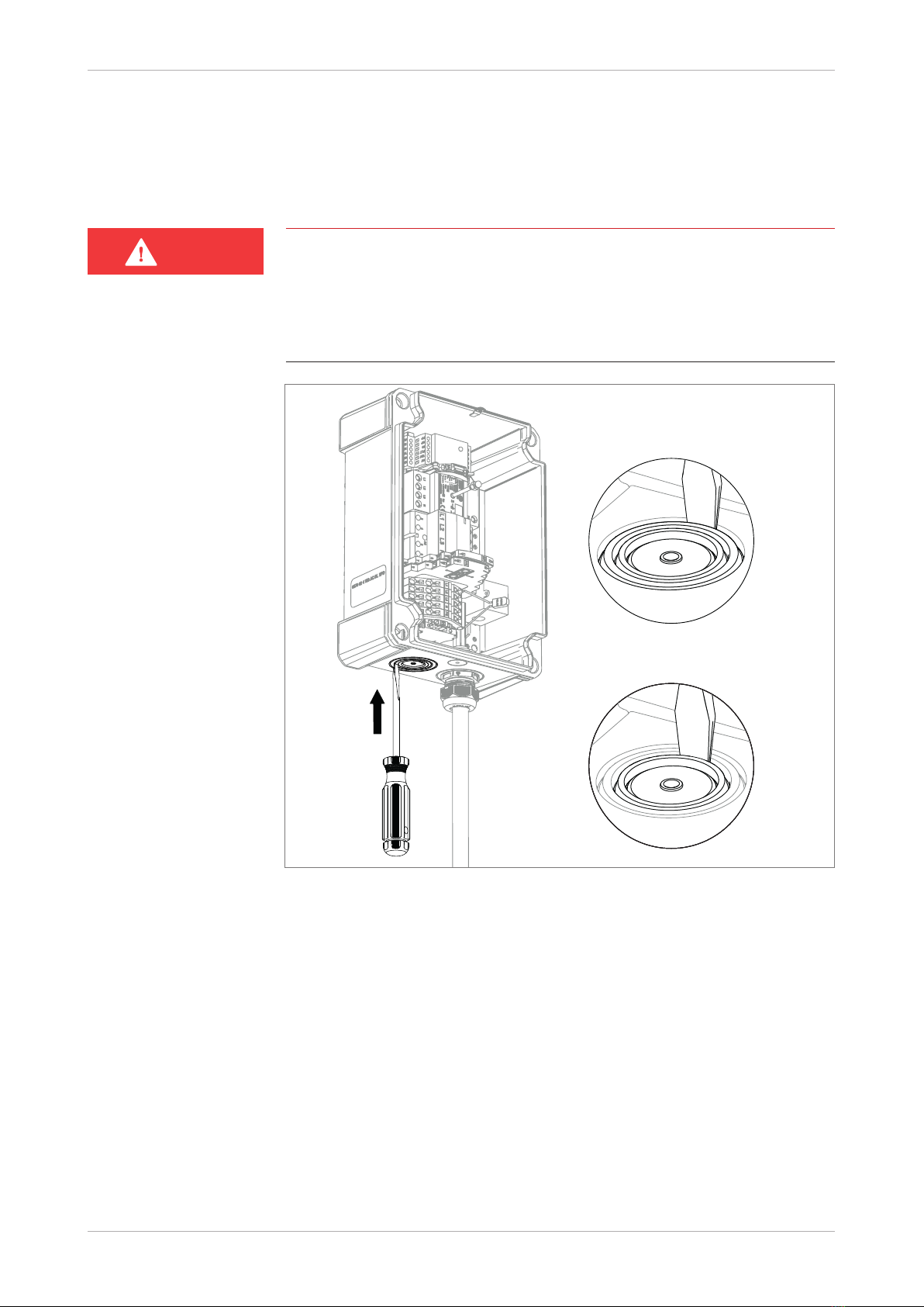
6.4 Connecting the charging station
Risk of electric shock!
Work on energised parts poses the risk of an electric shock with lethal
injuries. Before connecting the charging station, de-energisation must
be guaranteed by switching off the miniature circuit breaker. The voltage
may only be turned on again when the charging station is fully mounted
with a panel.
Fig. 7:
∅ 32 mm
Ion Basic/Key charging station:
∅ 25 mm
Ion Basic Protect/Key Protect
charging station:
Opening a knock-out entry
Note! The supply cable can be run into the charging station from above or be-
low through a knock-out entry. If the weather protection roof is mounted,
the supply cable is ideally inserted from below.
1. Break out the knock-out entry to insert the supply cable with a slotted
screwdriver.
DANGER

19 | EN
Mounting instructions for the Ion charging stations
Mounting and installation
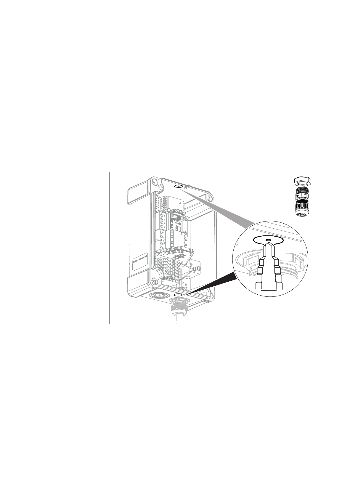
Fig. 8: Inserting a cable gland
2. Mount the supplied cable gland in the knock-out entry.
3. Insert the supply cable into the charging station through the cable
gland.
Fig. 9: Connecting the supply cable
4. Connect the supply cable to the plug-in terminals. With flexible cables,
use wire-end ferrules.
5. Check the charging controller and supply cable for correct earthing.
20 | EN OBO Bettermann
Mounting and installation
Using Modbus communication
6. Insert the two-wire data cable with supplied M12 cable gland into the
charging station and connect to the RSA and RSB inputs of the charging
controller.
Using the enabling contact
7. Insert the two-wire data cable with supplied M12 cable gland into the
charging station and connect to the IC and 0 V inputs of the charging
controller.
Note! If the Modbus communication is used simultaneously, the charging con-
troller can be connected to the higher-level system via a four-wire data
cable.
6.5 Mounting the data cable
∅12 mm
M12
Fig. 10: Drilling the M12 opening
Note! The data cable can be inserted into the charging station from above
or below, depending on whether a pressure compensation element is
mounted in one of the openings.
1. Drill the opening for the M12 cable gland from the outer side of the
box using a stepped drill. Take great care not to damage the devices
inside.
This manual suits for next models
1
Table of contents
Popular Automobile Accessories manuals by other brands


Scosche
Scosche FDQ01 manual

KW automotive
KW automotive 152 27 405 instruction manual

Mobility Networks
Mobility Networks RPS 300 Use and maintenance manual

Thule
Thule Railing Load Carrier 754 installation instructions

Cruz
Cruz 934-636 Assembly instructions

Altendorf
Altendorf E-Cruise installation instructions