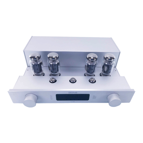
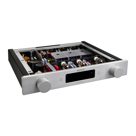
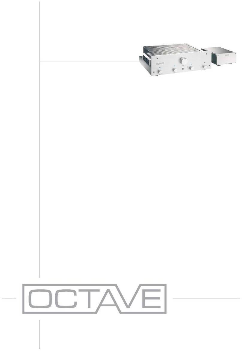
Octave HP 700 User manual

HP 700

FOREWORD
2
Congratulations and thank you for choosing the OCTAVE tube preamplifier
HP 700
You are about to enjoy the benefits of one of the world’s most innovative and
reliable preamplifiers, the HP 700. Take care of it, and your preamplifier will
provide you with many years of listening pleasure.
You often hear people claim that there has been no real progress in tube am-
plifier design for years. The operating principles of tubes have been docu-
mented extensively and are well known to amplifier designers. The same can,
of course, be said for transistor amplifiers.
Nevertheless, there is still room for further development with both of these tech-
nologies. This is both necessary and desirable. With tube amplifiers in particu-
lar, a general reluctance to depart from the classic circuit designs has not done
the technology any favors. Today's loudspeakers and source equipment pro-
vide better performance than ever before, but also make greater demands on
amplifiers. Modern sound reproduction equipment delivers a level of perfor-
mance at a price that simply would not have been possible 20 or even 10 years
ago.
These advances have been achieved through the application of cutting-edge
technology as it becomes available and affordable.
Integrating these technologies into amplifier design demands a detailed
knowledge of the inner workings of amplifiers and an appreciation of the sonic
ramifications of each modification.
We have specialized in tube amplification for the past 30 years, during which
time we have developed a number of innovative technologies that have earned
us a reputation as one of the leaders in the field.
We hope you will enjoy many hours of wonderful music with your OCTAVE
preamplifier.
Andreas Hofmann

CONTENTS
3
1. OCTAVE TECHNOLOGY ........................................................................................................ 5
OCTAVE amps in contrast to other tube amplifiers .................................................................. 5
Description HP 700 ................................................................................................................... 6
2. SAFETY INSTRUCTIONS........................................................................................................ 7
Before you begin ....................................................................................................................... 7
2.1.1. In case of emergency: disconnect the plug from the mains supply ............................... 7
2.1.2. Do not open the case ..................................................................................................... 7
2.1.3. Service and maintenance ............................................................................................... 7
2.1.4. Symbols and terms used in warnings ............................................................................. 7
2.1.5. Before connecting ........................................................................................................... 8
2.1.6. Grounding ....................................................................................................................... 8
Placement ................................................................................................................................. 8
2.2.1. Location .......................................................................................................................... 8
2.2.2. Cover .............................................................................................................................. 8
2.2.3. Ventilation ....................................................................................................................... 8
Warranty ................................................................................................................................... 8
3. SETTING UP ............................................................................................................................ 9
Checking the delivery contents ................................................................................................. 9
Connecting the amplifier ........................................................................................................... 9
Running in ................................................................................................................................. 9
4. OPERATION .......................................................................................................................... 10
HP 700 front panel .................................................................................................................. 10
5. CONNECTIONS ..................................................................................................................... 11
HP 700 rear panel ................................................................................................................... 11
6. EXTERNAL POWER SUPPLY .............................................................................................. 13
Front of power supply ............................................................................................................. 13
Rear of power supply .............................................................................................................. 13
7. MULTI-CHANNEL MODE ...................................................................................................... 14
The HP 700 in multi-channel mode ........................................................................................ 14
8. REMOTE CONTROL FOR VOLUME .................................................................................... 16
Remote control operating elements ........................................................................................ 16
Battery replacement ................................................................................................................ 16

CONTENTS
4
9. TUBES .................................................................................................................................... 17
Line tube layout with adjustment capability ............................................................................ 17
Phono tube layout ................................................................................................................... 18
Control unit tube layout ........................................................................................................... 19
Replacing tubes ...................................................................................................................... 20
Tube service life ...................................................................................................................... 20
10. OUTPUT RESISTANCE ......................................................................................................... 21
Adjusting the output resistance .............................................................................................. 2 1
11. OPTIONS ................................................................................................................................ 22
Option: Additional line-level input module .............................................................................. 22
11.1.1. Assembling the additional line-level input module ................................................ 22
11.1.2. Available line-level input modules: see inlay manual “In- and Output Modules”
23
Option HP 700 with phono ...................................................................................................... 24
11.2.1. HP 700 with phono RIAA ...................................................................................... 24
11.2.2. Subsonic filter ........................................................................................................ 25
11.2.3. Assembling the phono input modules ................................................................... 26
11.2.4. Available phono input modules: see inlay manual “In- and Output Modules”....... 26
Option: HP 700 with control unit ............................................................................................. 2 7
Option: HP 700 with stepped attenuator ................................................................................. 29
12. TROUBLESHOOTING ........................................................................................................... 30
Troubleshooting ...................................................................................................................... 30
13. TECHNICAL DATA ................................................................................................................ 31
In- and outputs ........................................................................................................................ 31
Dimensions ............................................................................................................................. 33
13.2.1. HP 700 preamplifier (dimensions in mm) .............................................................. 33
13.2.2. External power supply (dimensions in mm) .......................................................... 33
Diagrams ................................................................................................................................ 34
13.3.1. HP 700 line frequency response ........................................................................... 34
13.3.2. FFT interference spectrum .................................................................................... 34
13.3.3. Control range and balance control frequency response ....................................... 35
13.3.4. Line stage hum and noise level ............................................................................ 35

OCTAVE TECHNOLOGY
OCTAVE amps in contrast to other tube amplifiers
5
OCTAVE TECHNOLOGY
OCTAVE amps in contrast to other tube amplifiers
Sound
The design goal of OCTAVE amplifiers is honest, natural sound reproduction. The
sound characteristics of an amplifier are derived from the sum of all its parts. Tubes
themselves do not guarantee high quality sound.
Amplifier design
The frequency range and output resistant limitations of classic tube designs are ev-
ident as soon as you connect the amplifiers. These designs often only perform to
their full potential when they are used with special cables and power amplifiers.
OCTAVE amplification and power supply technology has largely overcome these
well-known problems. Thanks to their unique output stage design, they will maintain
their optimum sound quality with virtually any power amplifier, irrespective of the
cables.
Control +
monitoring
OCTAVE employs the latest electronic circuit designs to create the best possible
operating conditions for the tubes, and thus for the amplifier itself.
OCTAVE tube technology
OCTAVE amplifiers are equipped with a proprietary control and monitoring system
we call Power Management. This is an “electronic brain” within the amp that regu-
lates and controls all of the amplifier's functions. It includes the Soft Start Electron-
ics that gently ramp up the heating and supply voltages to minimize wear and tear
on the components. In the event of a problem, the Power Management’s protection
system disconnects the unit from the power supply. Power Management helps us
to achieve a completely consistent sound while at the same time ensuring the total
reliability of our products.
Hand built
OCTAVE amplifiers are hand built and individually tested. They are designed and
developed by Andreas Hofmann. The company has its own winding department, in
which all transformers are especially custom-wound for each amplifier.
Made in Germany
OCTAVE amplifiers are 100% built in Germany. Our employees are highly qualified
and committed. We collaborate closely with local specialist subcontracting compa-
nies. The hardware components are all manufactured on modern CNC machines.
Power
Management
Amplifier +
sound
Power supply
+ additional
functions

OCTAVE TECHNOLOGY
Description HP 700
6
Description HP 700
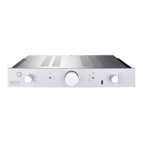
The HP 700 is a member of a new generation of tube amplifiers built by OCTAVE. The first model of
this line was the Jubilee reference preamplifier, followed by the HP 500 SE and HP 300 SE pream-
plifiers. This new development is based on a newly developed power supply with precise, low-noise
voltage control circuits. The newly developed amplifiers are extremely low-noise and low-distortion.
In conjunction with the exceptionally low output resistance, virtually every output stage can be
achieved with any signal cables for the first time ever with a tube preamplifier. Furthermore, the
HP700 is manufactured perfectly, as goes without saying for all OCTAVE amplifiers. The solid
connecting sockets allow the connection of high-quality NF wires with large plugs. As with all OC-
TAVE amplifiers, the HP 700 is equipped with a real power switch. Every OCTAVE product is built
in Germany in single-piece production and is subject to a 100% check. A 48-hour endurance run
completes the final inspection. Transformers are individually designed and produced for each
model in our own house.
Special characteristics of the HP 700
Once again, OCTAVE is the pioneer with innovative equipment features.
It is equipped with an external power supply, while the internal supply voltages feature com-
plex electronic regulation, ensuring a consistent sound even with a highly fluctuating power sup-
ply. In addition, the built-in control logic guarantees top reliability and achieves a theoretical
maximum service life of the tubes (up to approximately 50,000 h) thanks to soft-start techniques.
An additional function of the power supply is a protective circuit, which releases the output of
the HP 700 via a relay with a time delay or disconnects it immediately in case of a malfunction.
Click interferences caused by a loss of power supply, etc. are therefore ruled out completely.
The multichannel bypass function makes the HP 700 one of the most versatile preamps in
this range (see chapter 7, page 14). An RCA or XLR input can be selected for the bypass func-
tion. This set-up in the HP 700 is achieved through logic-controlled input selection. The switching
elements are high-quality industrial-grade gold contact relays.
The HP 700 features two XLR inputs, one of which can also be used for the bypass function.
Three-stage gain adjustment. This feature allows for the optimal adjustment of the overall gain
to the efficiency of the loudspeaker or the input sensitivity of the power amplifier. This achieves
an optimum volume level and allows for sensitive volume control.
Adjusting the output resistance of the line stage. The output resistance can be set between
100 and 300 ohms in two settings. This allows the sound of the preamplifier to be adjusted op-
timally to the signal cable used and to the input impedance of the power amplifier.
XLR outputs with special balanced transformers as in studio technology. Galvanically iso-
lated transformer-balanced XLR outputs are unrivaled in terms of sound quality and prevent
humming due to earth loops.
A further feature is the monitor output. An A/D converter for a PC or a classic tape can be
connected here.
Arbitrary inputs through module technology (option). Up to two input modules (line and
phono) can be used simultaneously. This ensures the optimum input for every configuration.
The modules can be retrofitted at any time.
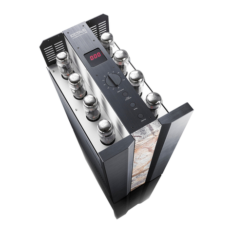
Advanced adjustment functions with the control unit option. The control unit includes a
tone control in tube technology, two precise level controls for exact balance correction, and a
switching apparatus to select an output (three outputs in total).
SAFETY INSTRUCTIONS
Before you begin
7
SAFETY INSTRUCTIONS
Before you begin
2.1.1. In case of emergency: disconnect the plug from the mains supply
Never use an amplifier that is damaged or faulty. Make sure it has been labeled as defective and
that it cannot be used until it has been repaired by a qualified service engineer.
Make sure that there is easy access to the IEC socket and power cable.
2.1.2. Do not open the case
There are dangerously high voltages and hot tubes inside this equipment. To avoid a burn or the risk
of electric shock, never allow anyone except qualified personnel to open the case or remove the grill.
2.1.3. Service and maintenance
For reasons of safety, please ensure that servicing, repairs and other modifications to OCTAVE
equipment are carried out only by a qualified technician. Defective fuses should also only be replaced
by a qualified technician. Always replace fuses with ones of the same type and rating. If your amplifier
requires servicing, please ship or take your equipment directly to OCTAVE or to one of our authorized
service centers.
2.1.4. Symbols and terms used in warnings
The following warnings, symbols and terms are used in this document in compliance with the Amer-
ican National Standard ANSI Z535.6-2011:
The general danger symbol, in conjunction with the terms CAUTION, WARNING, or
DANGER, warns of the risk of severe injury.
The triangle symbol with the lightning bolt warns of non-isolated, dangerous voltages
inside the case and of hazards posed by electrical shocks. Follow all subsequent in-
structions to avoid injury or death.
ATTEN-
TION
Indicates a danger that could lead to damage or destruction of the device.
CAUTION Indicates a danger that represents a low or medium risk of injury.
WARNING Indicates a danger that could lead to death or severe injury.
DANGER Indicates a danger that will result in death or severe injury.
Warning format
WARNING TERM
Type and source of danger
Consequences of ignoring the warning
► Action needed to avoid danger

SAFETY INSTRUCTIONS
Placement
8
2.1.5. Before connecting
Make sure that the voltage of your amplifier matches your local supply voltage.
2.1.6. Grounding
This amplifier is a protection class 2 device (without an earth conductor), while the power supply is
class 1. As a result, a three-pin power cable with a protective ground contact must be used (included
in the scope of delivery).
Placement
2.2.1. Location
OCTAVE equipment is designed strictly for use in a dry domestic environment. Do not use it in
open air or in damp environments!
Never place plants or liquid-filled containers on your amplifier. Take care that objects do not fall
or liquids are not spilled into the enclosure. Should this happen, disconnect the mains plug im-
mediately and have your amplifier checked by a qualified service technician.
Condensation may form if the amplifier is taken from a cold environment into a warm one. In this
case, wait until the amplifier has reached room temperature and is dry before switching it on.
Avoid installing the amplifier close to sources of heat, such as heaters, or anywhere that it may
be in direct sunlight.
Do not operate your OCTAVE amplifier near flammable materials, gases, or vapors. Avoid areas
where there may be heavy accumulations of dust or where the amplifier may be subject to me-
chanical vibration.
Place your OCTAVE amplifier on a stable, even surface.
2.2.2. Cover
Never operate the amplifier without the cover.
2.2.3. Ventilation
Ensure sufficient air circulation around your amplifier. If you intend to install your equipment in a
cupboard or a shelf unit, ensure that there is at least a 10 centimeter gap between the ventilation
slots and the walls all around the amplifier.
To prevent heat accumulation, the back of the cupboard should have ventilation holes.
Do not rest the equipment on a soft surface such as carpet or foam sheeting.
Warranty
OCTAVE can only guarantee the safety, reliability and performance of this unit if modifications and
repairs are carried out by specialized personnel and if the amplifier is operated in accordance with
the instructions contained in this manual.

SETTING UP
Checking the delivery contents
9
SETTING UP
Checking the delivery contents
Scope of delivery
HP 700
External power supply
Power cable
Remote control
TX10 pin wrench to open the cover
Manual with warranty card
Connecting the amplifier
1. In your own interest, please observe the safety instructions and positioning information
(see chapter 2, page 7)
2. Before connecting your OCTAVE amplifier, switch off all other equipment that you intend to con-
nect to it. This will avoid a source of possible malfunctions when you plug these components in.
3. Connect the inputs from your power amplifier to the appropriate outputs on the HP 700.
4. Connect your loudspeakers to your power amplifier, making sure that you observe the correct
polarity (positive on the amplifier to positive on the speakers).
5. Check that the amplifier is switched off before connecting the power cable to the wall socket.
6. Check that the volume control is not set at maximum before playing music through the pream-
plifier and that the function switch (1) is set to the setting Gain Low, Med, or High.
7. Switch on the HP 700 using the power switch on the power supply. (See chapter 4, page 10)
Note The preamplifier requires approximately
2 minutes to warm up. During this warm-
up period, the outputs are shorted to ground
to avoid disturbances.
Do not switch the function switch during the
warm-up phase, as this unnecessarily ex-
tends the start-up procedure.
8. Switch on the other components in any order.
Running in
All OCTAVE equipment is subject to a 48-hour endurance run to burn in the tubes. The tubes are
preselected for use in each particular model. The sound quality of tube equipment improves
throughout the initial running-in period of up to three months.
Power switch

OPERATION
HP 700 front panel
10
OPERATION
HP 700 front panel
Legend
(1) Mode switch
(function switch)
The muting, line stage gain, home theater bypass multi-channel func-
tion, and tone control are activated here.
Muting The muting LED illuminates when muting is on and during the start-up
phase. In this setting, the preamplifier outputs are short-circuited and
music cannot be played. This switch position should be activated while
connecting source devices to the HP 700.
Gain Low, Med, and High The gain setting can be selected according to the efficiency of the other
components. When you change the position of the switch, the muting
function is activated for 20 seconds to prevent switching malfunctions.
Bypass HT In this setting, the gain of the line stage is 1 and the volume control is
bypassed. This setting is intended for multi-channel applications with
volume control on the multi-channel receiver. The bypass HT RCA in-
put is separate; the bypass function can be switched to an XLR input.
TC On This LED illuminates if the tone control is on (only available for control
unit option, see section 11.3, page 27)
Start This LED only illuminates during the two-minute start-up phase. During
this period, the muting LED also illuminates.
(2) Volume control (Also optionally available as a step switch, see section 11.4)
(3) IR sensor To ensure the correct function of the remote control, make sure that
the infrared sensor is not covered.
(4) Input selector switch For input selection. The selected input is indicated with an LED.
IN1-SL1, IN2-SL2 Input module 1
Input module 2
The signal LEDs for IN1 and IN2 only il-
luminate if a module is installed!
IN3-XLR, IN4-XLR XLR input for line-level sources
IN5-RCA, IN6-RCA,
IN7-RCA
RCA input for line-level sources

CONNECTIONS
HP 700 rear panel
11
CONNECTIONS
HP 700 rear panel
Legend
(5) GND connection Ground connection for phono
(6) IN 1 SL1 Slot for a phono or line input module
(7) IN 2 SL2 Slot for a phono or line input module
(8) IN 5 RCA input Line-level input for CD, tuner, etc.
(9) IN 3 XLR input Balanced line-level input for CD, DAC, etc.
(10) IN 6 RCA input Line-level input for CD, tuner, etc.
(11) IN 7 RCA input Line-level input for CD, tuner, etc.
Note On the connector panel, the bottom row of sockets (red) is the right channel, while the
top row of sockets (white) is the left channel.

CONNECTIONS
HP 700 rear panel
12
Legend
(12) IN 4 XLR input Balanced line-level input for CD, DAC, in bypass setting, can be
used as alternative home theater input.
(13) RCA bypass Home theater input for multi-channel receiver
(14) Monitor outputs Unregulated outputs for recording equipment, computers, etc.
(15) OUT 1 RCA outputs for power amplifiers
(16) OUT 2 RCA outputs for power amplifiers
(17) Name plate With serial number and version
(18) OUT 3 XLR output for balanced power amplifiers. 1 = ground, 2 = posi-
tive, 3 = negative ground lift XLR. With the ground lift, the XLR
outputs can be isolated from the signal ground for the preampli-
fier. Setting O corresponds to the ground isolation. In setting I,
the ground of the XLR outputs over 3.3 ohms is connected to the
preamplifier ground. Isolating the ground is useful when multiple
devices in the system have a power supply with a three-pin
grounding plug to prevent ground loops.
(19) Connection for the external power supply

EXTERNAL POWER SUPPLY
Front of power supply
13
EXTERNAL POWER SUPPLY
The HP 700 is switched on and off using a switch on the power supply.
Front of power supply
Legend
(20) Power (switch)
power supply
The LED on the power supply illuminates when the power supply is on.
During the start-up phase, the start and muting LEDs illuminate on the pream-
plifier. After the start-up phase, the start and muting LEDs go out; if the mode
switch is not set to the muting setting, the device is ready to play music.
(21) Control light Power on/off
Rear of power supply
Legend
(22) Power input, IEC socket
(23) Serial no. and supply voltage
(24) HP 700 connecting cable

MULTI-CHANNEL MODE
The HP 700 in multi-channel mode
14
MULTI-CHANNEL MODE
The HP 700 in multi-channel mode
Many customers want to use their multi-channel system for a TV, DVD recorder, etc. without giving
up the sound of a high-end stereo system to listen to their music. In such cases, these customers
either set up two separate systems (e.g. doubled power amplifiers, doubled speakers, etc.) or have
to fiddle with plugs every time they want to hear multi-channel and classic stereo.
The HP 700 is the solution to this problem.
With the HP 700, it is possible to use the two-channel amplifier/speaker combination as part of the
multi-channel system. This eliminates any double volume control issues. Normally, the two-channel
combination for front right and left is used since these are the main channels in the multi-channel
system. (5 + 1, 3 + 1 systems)
For this reason, both the front channels (right and left) on the multi-channel source are connected to
the bypass input (13) on the HP 700 if the multi-channel device only has RCA outputs. If the multi-
channel receiver also has balanced outputs for the two main channels, the bypass multi-channel
input on the HP 700 can be switched to the balanced input IN 4 (12).
The signals “front left” and “front right” on the multi-channel source device are “connected through”
with the function switch on the front (1) (Bypass HT setting) and are available directly for the two-
channel power amplifier at the RCA outputs or (balanced) XLR outputs. In the “Bypass” setting, the
“Bypass” LED illuminates; the “Gain med” LED, and the “IN 4” illuminate if the bypass input selector
switch is set to “IN 4 XLR”. In this mode, the volume for these outputs must be set on the multi-
channel source device.
Selector switch for multi-channel input/RCA-XLR
This switch determines the input for the multi-channel/home thea-
ter function.
Toggle switch up: IN 4 XLR is the multi-channel input.
Toggle switch down: Bypass RCA is the multi-channel input.

MULTI-CHANNEL MODE
The HP 700 in multi-channel mode
15
In multi-channel mode, i.e. in the “bypass” setting, the common volume of the multi-channel system
has to be set on the multi-channel source. For the RCA outputs and the balanced XLR output, the
volume control for the HP 700 is then disabled.
In this mode, the amplification factor of the HP 700 is 0 dB for RCA and XLR.
Multi-channel source
DVD player, etc.
Stereo/mono power
amplifier
Front – main loudspeaker
Three-channel power
amplifier for the
additional channels
RCA/XLR
input L
RCA/XLR
input R

REMOTE CONTROL FOR VOLUME
Remote control operating elements
16
REMOTE CONTROL FOR VOLUME
Remote control operating elements
Legend
(1) Volume up
(2) Volume down
Battery replacement
1. Use a “Philips 1” screwdriver to disassemble the base plate.
2. Remove the batteries.
3. Insert two new AAA 1.5 V batteries.
Tip Make sure not to press the buttons while inserting the batteries!
If the remote control does not work after the batteries are replaced, remove the new
batteries and wait at least 2 hours.
You can then re-insert the batteries and the remote control should work.
4. Replace the base plate taking care not to tighten the screws too much.
Note
After use, the batteries we have supplied for the remote control can be returned to the
point of sale free of charge. Please do not throw them in the garbage.
You cannot control the volume with the remote control in case of the option stepped
attenuator.

TUBES
Line tube layout with adjustment capability
17
TUBES
Line tube layout with adjustment capability
WARNING
Electric shock! Parts carrying dangerous voltages may be exposed when
opening the cover and injury through electric shock.
► Before opening the cover, switch the device off and unplug the power cord.
Tube layout: line board
V 1 ECC82 (12 AU 7 ) (No option to adjust the tubes)
V 2, 3 2 x EF 800 (alternative 2 x EF 184)
or
Jumper setting for position EF:
Pin1 and Pin2 are bridged
2 x D 3 A (alternative E 180 F)
Jumper setting for position D3:
Pin2 and Pin3 are bridged
Factory settings:
V1 12 AU 7 Tung Sol
V2 + V3: 2 x EF 800 Telefunken (position EF)

TUBES
Phono tube layout
18
Phono tube layout
German designation International designation
V 4 ECC 83 12 AX 7
V 5 ECC 81 12 AT 7
V 6 ECC 88 6922, 6 DJ 8

TUBES
Control unit tube layout
19
Control unit tube layout
German designation International designation
V 7 ECC 88 6922, 6 DJ 8
Replacing the V 7 tube
Note The control unit cannot be disassembled during tube replacement, as it is physically
connected to the front.
1. Disassemble the shortened cover.
2. If your device is equipped with the phono RIAA board, first remove the V 6 tube of the phono
RIAA board.
3. Below the control unit, carefully remove the V 7 tube in the direction of the arrow.

TUBES
Replacing tubes
20
Replacing tubes
ATTENTION
Improper disassembly
Damage to the tubes due to improper disassembly or assembly.
► Changing tubes is a job for qualified technicians!
1. Switch off the preamplifier, unplug the power cord from the wall socket, and allow the unit
10 minutes to cool down.
2. Remove the cover by loosening the M4 torx screws (a total of 10 for the cover without control
unit and 7 for the shortened cover with control unit). Do not remove the control unit from the
device.
3. Carefully remove the tubes from their sockets, taking care not to exert sideward pressure on the
sockets.
4. Fit new tubes. Please ensure that the tube pins are all perfectly straight before inserting your
new tubes. Straighten any bent pins very carefully by hand if necessary.
Cleaning
tips
Cleaning agents and contact cleaners are not recommended for tube sockets.
► Clean dirty sockets with compressed air and carefully clean tarnished tube
pins using a wire brush or toothbrush.
Please
note:
No adjustments are necessary to your amplifier after fitting new tubes.
It may take new tubes some time (up to 300 hours) to achieve their optimum sound
quality.
Manufacturing faults in tubes may only become evident after about 100 hours of
use. You should therefore be wary of installing untested tubes.
Tube service life
Thanks to the protection circuits and soft start electronics, the output tubes used in your amplifier
should achieve an average service life of 5 to 10 years.
Because the tubes have different service lives, it should never be necessary to renew the entire
tube complement at the same time.
Table of contents
Other Octave Amplifier manuals

Octave
Octave JUBILEE Mono User manual

Octave
Octave JUBILEE Pre User manual

Octave
Octave Phono Module User manual

Octave
Octave Black Box User manual

Octave
Octave V 80 SE User manual

Octave
Octave HP 300 SE User manual

Octave
Octave HP500MK3 User manual

Octave
Octave V 50 MKII User manual

Octave
Octave RE 280 MK2 User manual

Octave
Octave JUBILEE MONO SE User manual

Octave
Octave V 70 Class A User manual

Octave
Octave HP 300 MK2 User manual

Octave
Octave Super Black Box User manual

Octave
Octave V 16 Single Ended User manual

Octave
Octave RE290 User manual

Octave
Octave JUBILEE 300 B User manual

Octave
Octave V70 User manual

Octave
Octave V110 User manual

Octave
Octave v70se User manual

Octave
Octave RE 320 User manual